Innovations In Cement Manufacturing: Complete Guide & Downlo
At the discharge end of the kiln, the clinker is red hot, carrying on the order of 1.0 million Btu per short ton of thermal energy, and still to some extent reacting chemically toward the creation of the clinker minerals, and Chapter 3.8 of the Innovations in Cement Manufacturing series, written by Hans E. Steuch, treats the equipment that manages this formidable material flow: the clinker cooler. In cement manufacturing, the formation of the clinker nodules occurs at the entrance to the hottest part of the kiln with a material temperature of around 1,280°C, and the clinker, preferably in the form of 10-mm to 25-mm size nodules, exits from the front end of the kiln into the cooler. It is critical that cooling of the clinker is rapid to secure a phase composition that imparts adequate cementitious properties, and it is equally important that the heat exchange between the clinker and the air is efficient to ensure proper cooling while maximizing the recovery of heat to the secondary air, the tertiary air, and the related process requirements. This article expands the original chapter into a complete technical package covering the history of the cooler, the types of coolers, the theory of the heat exchange, the modern reciprocating grate cooler in detail, the automation and optimization of the cooler, and the innovations that continue to improve its performance.
Like other processing equipment, clinker coolers have undergone significant development over the past years. The original chapter describes the advent of the clinker coolers, discussing and describing the various types of coolers presently available, and it focuses on the reciprocating grate cooler and its latest developments while tracing the historical development of that machine in relation to increasingly fuel-efficient kiln systems. The theoretical mass and heat balance equations that describe the steady state and the heat recuperating efficiency are presented, followed by a practical discussion of how to automate and optimize the operation of the cooler. This article follows that same route: history, types, theory, the modern reciprocating grate cooler, automation, optimization, and the future of cooling technology.
1. Why the Clinker Must Be Cooled
The purpose of the clinker cooling is twofold, and the original chapter states both parts precisely. The first purpose is to recoup the heat of the clinker, thereby making the process energy-efficient: the thermal energy carried by the hot clinker, on the order of 1.0 million Btu per short ton, is recovered into the combustion air and returned to the kiln system, and that recovery is one of the largest single terms in the thermal balance of a well-run plant. The second purpose is to secure the quality of the product: the clinker must be cooled rapidly to lock in the phase composition that imparts the adequate cementitious properties, because the phases that form at the clinkering temperature must be preserved through cooling.
The quality of the cooling determines the quality of the cement. A rapidly cooled clinker preserves the reactive, partly glassy microstructure, the fine alite and the distorted interstitial material, that hydrates and develops strength well, and it fixes the distribution of the minor components in their useful phases. A slowly cooled clinker allows recrystallization and the redistribution of the phases, an alite that may decompose, and a hard, unreactive product that grinds poorly and performs weakly, exactly the chemistry that the clinkering chapters of the series describe.
The energy side of the cooling is equally direct. The heat recovered by the cooler appears in the secondary air, which is the combustion air of the kiln burner, and in the tertiary air, which feeds the calciner, and every kilocalorie of recovered heat is a kilocalorie not spent on fuel. The thermodynamic measure of the recovery is the cooler efficiency: the ratio of the heat returned to the process to the heat available in the clinker, and the modern coolers achieve efficiencies that the older designs never approached.
The cooling also serves the downstream process: the clinker must reach the cement mill at a temperature suitable for the grinding, the conveying, and the storage, and the discharge temperature of the clinker is a design and an operating target in its own right. The cooler therefore performs triple duty, quality, energy, and logistics, and its design and its operation are correspondingly consequential for the whole plant.
2. The Development History of the Cooler
The original chapter traces the development of the clinker cooler in relation to the increasingly fuel-efficient kiln systems, and that history is instructive because the cooler’s evolution was driven by the kiln’s evolution. The early kilns were wet or long dry machines whose heat consumption was dominated by the preheating inefficiencies, and their coolers were comparatively simple devices whose recovery was modest. As the kilns became more efficient, with the preheaters and the precalciners, the recovery of the clinker heat became a larger share of the total opportunity, and the cooler received corresponding attention.
The families of the cooler that the history produced divide by their architecture. The planetary coolers, mounted on the kiln shell as a ring of satellites, were popular in the 1960s and 1970s when many dry-process 4-stage preheater kiln systems were built around the world, particularly in Europe and Asia, and they achieved a compact, shell-integrated design whose simplicity appealed, but their limitations were real, and in North America most of the dry-process kilns were supplied with grate coolers instead.
The grate coolers, in which the clinker travels on a moving or reciprocating grate while air is blown up through the bed, became the workhorse of the modern era, and their development, the reciprocating grate cooler, the cross-bar and the step-grate designs, has continued through the decades to the present. The history shows a steady march of capacity: the cooler of a 10,000-tonne-per-day line is a machine of enormous proportions, handling the entire output of the largest kilns in the world.
Other families appeared and largely faded. The shaft coolers found a home in the lime industry, where the uniform size of the burnt lime suits them, but they carry the highest power consumption and the worst cooling uniformity for the cement clinker, and they never established themselves in the cement kiln service. The history’s lesson is the same as in the preheater chapter: the family that combines the throughput, the efficiency, the uniformity, and the reliability wins the service, and every rival that trades away one of those properties loses the contest.
3. The Families of Clinker Coolers
The original chapter’s survey of the types of coolers presently available can be organized into a clear comparison, and the following table consolidates the principal families with their operating characteristics, drawn from the chapter’s treatment and the industry data it cites:
| Cooler type | Architecture | Typical use | Key characteristics |
| Planetary (satellite) | Cylinders on the kiln shell | 1960s–1970s dry-process lines | Shell-integrated; no tertiary air takeoff; costly maintenance |
| Rotary (drum) | Rotating drum with lifting flights | Older and smaller lines | Simple; limited recovery and large footprint |
| Shaft cooler | Vertical shaft with internal air | Lime kilns; limited cement use | High power (10–12 kWh/t); needs uniform size |
| Traveling grate | Moving steel grate bed | Earlier grate installations | Continuous grate; foundation support |
| Reciprocating grate | Fixed and moving grate plates | Standard for modern lines | Best recovery; full tertiary air; automation |
The planetary cooler sized the contest: because it does not allow the withdrawal of the tertiary air for a calciner, and because most kiln systems built today have calciners, the planetary cooler has become a relic of the past, and its maintenance cost, with the cooler inlets wearing out too fast, sealed its fate. The reciprocating grate family, with its full tertiary air capability and its recuperation, became the standard, and the remainder of this article is devoted to its theory, its design, and its operation.
4. The Theory of the Grate Cooler: Mass and Heat Balance
The quantitative treatment of the cooler rests on the mass and heat balance of the clinker, the air, and the machine, and the original chapter presents the equations that describe the steady state and the heat recovering efficiency. The mass balance is the simpler side: the mass of the clinker entering the cooler equals the mass of the clinker discharged, and the mass flow of the air through the cooler is the sum of the secondary air, the tertiary air, and the vent air, each of which proceeds to its destination.
The heat balance describes the destination of the thermal energy of the clinker. The heat of the entering clinker is partitioned into the heat recovered into the process air, which is the useful term; the sensible heat of the discharged clinker, which leaves the system; the radiation and the convection losses from the cooler surfaces; the heat carried by the vent air; and the heat of the dust carried off with the air streams. The cooler efficiency is the ratio of the recovered heat to the total heat of the entering clinker, and the modern machines hold the losses to the minimums the engineering allows.
The recovery appears in the elevated temperatures of the air streams. The secondary air of a well-recuperating grate cooler reaches temperatures on the order of 900 to 1,000°C at the kiln hood, and the tertiary air is withdrawn at comparable temperatures; these are the temperatures that the combustion engineers assume in the design of the burner and the calciner, and the whole thermal architecture of the kiln system presupposes the cooler’s recovery. A degraded cooler therefore degrades the entire process.
The balance equations give the engineer the instruments for the daily work: the measured temperatures and flows close the balances, the discrepancies identify the leaks and the losses, and the computed efficiency is the figure of merit that the audits and the optimization use. The chapter’s insistence on presenting the equations, rather than only the qualitative description, is characteristic of the series’ standard and is the foundation of the cooler’s modern control.
5. The Reciprocating Grate Cooler in Detail
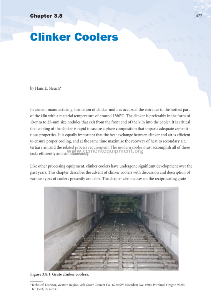
The reciprocating grate cooler is the centerpiece of the chapter and of the modern industry, and its description requires the full anatomy of the machine. The cooler consists of a long, slightly inclined housing into which the clinker falls from the kiln through the hood, and a grate floor divided into rows of fixed and moving grate plates, the moving rows reciprocating with a stroke and a frequency that advance the clinker bed toward the discharge end while the fixed rows channel the under-grate air upward through the bed.
The under-grate air is supplied by a fan system segmented into compartments along the length of the cooler, with each compartment’s flow controlled individually, and the air passes through the grate openings, fluidizes the bed, and collects the clinker heat before leaving the bed. The first compartments of the cooler deliver the hottest air, the secondary and the tertiary air streams; the middle compartments recover the moderate heat; and the last compartments cool the clinker to the discharge temperature with the cooler air, before the vent air is cleaned and exhausted.
The bed of the clinker on the grate is the reacting surface: its depth, its uniformity, and its motion set the quality of the heat exchange, and the design of the grate plates, the air distribution, and the drive system is what makes a good cooler different from a poor one. The discharge of the cooler passes through the clinker crusher, which reduces the larger nodules and the ash balls, and the crushed clinker leaves the cooler at the targeted discharge temperature for conveying to the clinker storage or the cement mill.
The development of the reciprocating grate cooler has been continuous: the air distribution is refined with the perforated and the cascade grate plates, the drives are modernized with the hydraulic systems, and the containment of the dust is improved with the double-pane and the sealed designs. Each generation of the machine has been delivered with a higher air-to-clinker efficiency and a lower power consumption, and the current generation operates with a recovery that the designers of the planetary era could not have imagined.
6. Air Distribution and the Temperature Profile of the Bed
The quality of the cooling is set by the distribution of the air through the bed, and the chapter’s operational discussion turns on the management of that distribution. The under-grate compartments each deliver their controlled air flow, and the pattern of the flows establishes the temperature profile along the cooler: the first compartments, under the hottest clinker, receive the largest share of the air and produce the hottest recovery streams, while the last compartments complete the cooling with the remainder.
The response of the bed is read through the under-grate pressures: the pressure underneath each compartment reflects the resistance of the clinker bed above it, and a shallow bed, a burned-through area, or a large lump all show up as pressure anomalies. The pressure profile is therefore the operator’s window into the bed, and the modern control systems use the individual compartment pressures as the primary feedback for the air distribution.
An uneven bed is the classic enemy of the coolers. When the clinker arrives unevenly, with the coarse nodules rolling and the fine material packing, the air channels through the thin spots and bypasses the thick ones, leaving the hot pockets un-cooled and the discharge temperature high. The design answers are the air-distribution plates that homogenize the flow and the hydraulic drives that smooth the grate motion, and the operating answer is the discipline of the kiln discharge itself, because a cool, even cooler starts with an even kiln.
The vent handling completes the air path. The vent air, the stream that is not recovered into the process, carries the residual heat and the dust, and it is cleaned in the bag filter before the stack, with the dust returned to the process. The vent volume is minimized by the design, because every cubic meter of vent is a cubic meter of heat lost, and the recovery maximization of the modern coolers is, in substantial part, the minimization of the vent.
7. Recuperation: Secondary Air, Tertiary Air, and the Hood Balance
The recuperation is the heart of the cooler’s value, and its management is the heart of the cooler’s operation. The recovered heat appears in three destination streams, and the partition among them is set by the needs of the process and the geometry of the system. The secondary air passes through the kiln hood into the kiln burner, and its temperature, on the order of 900 to 1,000°C, is the single most important recovery figure, because it is the temperature at which the kiln’s combustion air is delivered.
The tertiary air is withdrawn from the hood or from a dedicated takeoff and is ducted to the calciner, and its withdrawal is one of the decisive innovations of the precalciner era, as the preheater chapter established. The amount and the temperature of the tertiary air set the operation of the calciner, and the split between the secondary and the tertiary streams is an operating variable that the control systems manage to balance the kiln and the calciner.
The hood balance is the engineering instrument of the partition: the hood is the chamber where the kiln discharge, the burner, and the air streams meet, and its pressure, its temperature, and its flows are the data of the recuperation management. The false air at the hood, the leaks through the kiln seals and the hood joints, is the enemy of the balance, because it enters the recovery streams cold and dilutes them, and the seal discipline is a permanent operating task.
The recuperation figures enter the broader thermal balance of the plant, and the specific heat consumption of the kiln system is directly dependent on the cooler’s recovery: every degree of secondary air temperature is worth a measurable amount of fuel, and the audits of the plant routinely evaluate the cooler’s recuperation as one of the largest single opportunities. The chapter’s equation for the recovering efficiency is the instrument of that audit.
8. The Cooling Quality and Its Effect on the Clinker and Cement
The cooling quality of the cooler is as important to the cement as the recuperation is to the fuel, and the chapter’s emphasis on the rapidity of the cooling connects the machine to the product. The clinker leaves the kiln at the clinkering temperature, and the cooler’s task is to drop the temperature through the critical range quickly, freezing the high-temperature phase assemblage before the recrystallization and the phase changes can proceed.
The benefits of the rapid cooling are read in the cement mill and in the concrete. The rapidly cooled clinker is more reactive, developing its strength faster and more completely; it is more easily ground, reducing the finish mill power consumption, which is one of the largest electricity uses in the plant; and its microstructure, the fine, distorted alite and the glassy interstitial material, is the microstructure that the microscopy of the quality chapter reads as the sign of good process control.
A poorly cooled clinker shows the opposite symptoms: the hard, unreactive material that resists grinding, the alite that has decomposed, the redistribution of the sulfur and the alkalies into the phases that hurt the cement’s behavior, and the free-lime relapses that the slow cooling of the under-cooled nodules can cause. The coolers of the modern plants therefore operate with faster and more uniform cooling than the older machines, and the product benefits proportionally.
The discharge temperature of the clinker is the final quality variable of the machine: the clinker discharged above the design temperature burdens the conveying, the storage, and the finish mill, and the modern coolers hold the discharge temperature within their design band, typically of the order of 100 to 150°C above the ambient, with the air discipline and, where needed, with the water injection that the chapter mentions in the context of the shaft cooler.
9. The Automation of the Cooler Operation
The automation of the cooler has been one of the most productive areas of the process innovations, and the original chapter’s practical discussion of how to automate and optimize the cooler’s operation points to the modern practice. The automation starts at the measurement layer: the under-grate pressures, the air flows and the temperatures of the compartments, the bed depth detectors, the discharge temperature, and the hood and the recuperation temperatures are all measured continuously, and the data are the eyes of the control system.
The control layer uses the measurements to hold the three primary objectives of the cooler. The first objective is the constant discharge temperature of the clinker, controlled by the grate speed: a rising discharge temperature signals a bed moving too fast or a cooling air too scarce, and the grate is slowed or the air increased. The second objective is the recuperation temperature, controlled by the air distribution and the total air: the recovery is maximized by holding the secondary air at its peak within its constraints. The third objective is the protection of the machine, the limiting of the grate plate temperatures and the avoidance of the hot spots that damage the plates.
The advanced control layer adds the optimization. The multivariate controllers coordinate the grate speed, the compartment airs, and the vent flow to hold the discharge temperature and the recovery simultaneously, while the model-based methods predict the bed behavior and act before the disturbances arrive. The result is a cooler that operates on the edge of its design envelope, delivering the maximum recovery and the minimum power for the actual bed, which is precisely what the manual operation cannot achieve.
The automation converts the cooler from a mechanical follower of the kiln into a managed contributor to the process, and the integration of the cooler control with the kiln and the calciner control completes the control architecture of the modern burning line. The operator’s role shifts to the supervision of the recovery, the handling of the abnormal bed conditions, and the coordination with the kiln, exactly the direction that the innovations series documents across all of the unit operations.
10. The Optimization of the Cooler Economics
The optimization of the cooler is ultimately an economic problem, and the chapter’s treatment supports the cost-based view of the machine. The economics of the cooler are the balance of the recovered fuel, the consumed power, the maintenance, and the machinery capital, and the operating optimum is the setpoint that minimizes the total cost rather than any single component.
The power consumption of the cooler is dominated by its fans, and every cubic meter of air through the bed costs fan energy, so the air discipline, the delivery of exactly the air the bed can use, is a direct cost lever. The recovery is the counterpart: every degree of the secondary air temperature is worth fuel, so the air that is blown must be blown where it returns the most, which is the first compartments under the hottest clinker. The conflict between the air economy and the discharge temperature is resolved by the optimization: the minimum air that still achieves the discharge target, distributed to maximize the recovery.
The maintenance economics complete the picture. The grate plates, the crusher hammers, and the fans wear and consume their spare parts budgets; the hydraulically driven grates have simplified the mechanical upkeep; and the design improvements, the better plate steels, the modular replacement, and the on-line inspection, have extended the intervals between the outages. The availability of the cooler is a full equal of its efficiency, because an unavailable cooler stops the kiln.
The optimization practice of the modern plant therefore tracks the cooler through a small set of KPI numbers: the specific power in kilowatt-hours per tonne, the discharge temperature, the secondary air temperature, the vent share, and the availability, and the continuous improvement activity, the air balancing campaigns, the seal repairs, and the automation tuning, drives those numbers toward their practical floor. The chapter’s balance equations are the instrument, and the economics are the objective.
11. The Dust Handling and the Environmental Management of the Cooler
The dust handling of the cooler is a distinct engineering system, and its environmental role completes the machine’s place in the plant. The air passing through the clinker bed carries the kiln dust and the clinker fines, and the vent air stream must be cleaned before it is exhausted, which the bag filter or the electrostatic precipitator performs at the end of the vent duct.
The dust collected from the vent is returned to the process, either to the kiln feed system or, in the case of the fine, alkali-rich material, to the cement or the disposal stream according to its quality. The return of the dust closes the material balance of the cooler, and the quality analysis of the returned dust, its alkali and the sulfate content, governs its routing, because the volatile-rich dust cannot be freely recirculated without disturbing the cycles of the tower.
The environmental equipment of the cooler is therefore managed as part of the volatile chemistry of the plant: the vent fan, the filter, and the dust handling are the instruments by which the fine material is either recovered into the product or removed from the system, and their operation is coordinated with the bypass and the raw mill dust systems that the process chapters describe. The cooler’s place in the environmental architecture of the plant is as significant as its place in the thermal architecture.
The emissions measured at the cooler, the dust loading of the vent, and the ancillary streams are part of the plant’s permit compliance, and their monitoring feeds the same reporting system as the tower and the kiln. The modern cooler, with its sealed design and its efficient filtration, contributes a negligible fraction of the plant’s total emissions, which is the environmental standard that the innovations of the machine have achieved.
12. Failure Modes and the Maintenance of the Cooler
The availability of the cooler depends on the management of its failure modes, and the chapter’s operational treatment implies the maintenance discipline that the plant follows. The classical failure modes of the reciprocating grate cooler are the grate plate wear and the breakage, the crusher hammer wear, the hydraulics of the grate drive, the fan and the filter reliability, and the seal and the casing degradation, and each has its typical signature and its planned response.
The grate plates wear by the abrasion of the sliding clinker and the thermal fatigue of the alternating hot and cool exposure, and the life of the plates is tracked through the inspection and the pressure-signature changes of the compartments. The crusher, which reduces the oversized nodules and the ash balls, carries the highest wear duty of the machine, and its hammers are a scheduled replacement item, with the crusher availability protected by the automatic load monitoring.
The hydraulic drive of the grates is the great reliability improvement of the modern design: it delivers the smooth, variable stroke that the bed requires without the mechanical wear of the older crank drives, and its maintenance is the routine servicing of the pumps, the valves, and the fluid. The fans and the filter are the classic rotating-machinery service items, with their bearings, their motors, and their bags on the scheduled inspection cycle.
The maintenance organization of the cooler is a scheduled, preventive system: the inspections at the kiln stops, the condition monitoring of the drives and the fans in service, and the spare parts strategy for the high-wear items, all coordinated with the bricking campaign of the kiln, because the kiln and the cooler are stopped and repaired together, and the outage cost is shared. The discipline converts the cooler’s wear from a random failure into a predictable cost, which is the operational definition of the availability management.
13. The Cooler in the Context of the Complete Kiln System
The original chapter’s perspective on the cooler is completed by its place in the complete kiln system, and the integration of the machine with the kiln, the calciner, and the mill is the frame in which its performance is judged. The cooler is the fourth corner of the burning line’s thermal square: the kiln burns, the calciner decouples, the preheater recovers, and the cooler returns the heat of the product, and the four corners are managed as one system by the control architecture of the plant.
The coupling of the cooler with the kiln is direct: the secondary air temperature is an input to the kiln’s combustion, and the cooler’s behavior feeds directly into the burning conditions, exactly as the operations chapter established. The coupling with the calciner is carried by the tertiary air, and the distribution of the recovery between the two streams is an operating decision that the control systems make continuously. The coupling with the finish mill is set by the discharge temperature and the cooling quality, which govern the grinding economics and the product.
The integrated view also governs the design: the cooler of a new line is designed together with the kiln, the calciner, and the preheater, so that the air flows, the temperatures, and the recovery of the whole system are optimized jointly rather than each machine to its own local optimum. The chapter’s insistence on the mass and heat balance is the instrument of that joint design, and the modern engineering practice carries it in the simulation tools of the plant’s design department.
The operational consequence of the integrated view is that the cooler cannot be operated as a local machine with local targets: its targets, the discharge temperature, the secondary air, the tertiary air, and the vent, are set by the needs of the kiln and the calciner, and its management is shared among the kiln operators, the process engineers, and the quality function. The chapter’s placement of the cooler within the series, after the kiln and the preheater chapters and before the mill chapters, is exactly the place the machine holds in the process.
14. Innovations and the Future of Clinker Cooling
The innovations of the cooler have been continuous, and the future directions can be forecast from the pressures on the process. The first direction is the further improvement of the recovery: the cooler designs continue to push the secondary air temperatures toward the practical ceiling, to reduce the vent share, and to recover the heat of the vent streams that are not returned to the process, including the integration of the vent heat with the raw mill drying and the district-heating applications where they are economic.
The second direction is the control and the digitalization: the model-based control of the cooler, the real-time optimization of the air distribution, and the data-driven monitoring of the bed and the wear are extending the performance and the predictability of the machine, and the digital twin of the cooler is becoming a standard engineering tool for the design and the diagnostics. The sensor array of the cooler, its pressures, temperatures, and flows, is among the richest data sources of the burning line, and the analytics of that data is a live front of the innovations.
The third direction is the accommodation of the changing fuel and feed regimes: the alternative fuels change the clinker’s size and its dustiness, and the cooler designs and controls are adapting to the broader range of the material behavior, including the handling of the larger agglomerates and the stickier material. The future kiln lines, with their higher capacities and their carbon-reduction equipment, will place correspondingly higher demands on the cooling, and the machine will continue to evolve as it has throughout its history.
The fourth direction is the combination of the cooling with the heat recovery for the wider plant: the low-grade heat of the cooler’s vent is a candidate for the drying, the power generation, and the external uses, and the economic viability of these integrations is being established as the energy prices and the carbon costs rise. The cooler, once a simple follower of the kiln, has become one of the most innovation-rich machines of the cement plant, and the chapter’s treatment is the record and the forecast of that development.
15. The Cooler Operating and Improvement Checklist
To consolidate the chapter into the plant practice, the following ordered list presents the operating and the improvement checklist that the cooler engineer runs continuously:
- Balance the mass flows: verify the clinker feed, the air streams, the dust return, and the discharge, closing the mass balance and accounting for the seals and the leaks.
- Close the heat balance: verify the recovery into the secondary and the tertiary air, the vent losses, the radiation, and the discharge sensible heat, and compute the recuperating efficiency.
- Hold the discharge temperature: manage the grate speed and the air distribution to hold the discharge within its band, responding to the bed’s pressure signature.
- Maximize the recuperation: prioritize the air to the first compartments, minimize the vent, hold the secondary air at its peak, and keep the hood sealed.
- Protect the machine: monitor the grate plate temperatures, the crusher load, the hydraulics, and the fans, and schedule the maintenance on the evidence.
- Coordinate with the kiln and the calciner: set the secondary-tertiary split with the fuel requirements, and communicate the bed quality back to the burning team.
- Improve continuously: track the KPI numbers, the specific power, the discharge, the secondary air, the vent, and the availability, and drive them down with the air-balancing and the control campaigns.
The checklist is the daily form of the chapter’s theory, equations, and practice, and the engineer who runs it keeps the cooler operating at the frontier of its design, which is the frontier of the plant’s fuel economy and clinker quality.
Frequently Asked Questions
Why is the clinker cooler so important to the fuel economy?
Because it recovers the heat of the red-hot clinker, on the order of 1.0 million Btu per short ton, into the secondary and the tertiary air that feed the kiln and the calciner. Every kilocalorie recovered is a kilocalorie not burned, and the recuperation of the modern grate coolers is one of the largest single terms in the thermal efficiency of the dry process.
Why must the clinker be cooled rapidly?
To secure the phase composition that gives the cement its strength and its reactivity. Rapid cooling freezes the high-temperature phases in their reactive, partly glassy state, while slow cooling allows recrystallization, possible alite decomposition, and a hard, unreactive product that grinds poorly and develops strength weakly.
Why did the planetary cooler disappear from the modern plants?
Because it could not provide the tertiary air withdrawal that the precalciner systems demand, its maintenance was costly, and its size was limited. As the precalciner technology became the standard, the reciprocating grate cooler, with its full tertiary air capability and its superior recovery, replaced the planetary machines.
How does the operator see what is happening in the clinker bed?
Through the under-grate pressures of the compartments. The pressure below each compartment reflects the resistance of the bed above it, so the pressure profile maps the bed depth and its uniformity: a low-pressure compartment signals a thin or channeled bed, and a high-pressure one signals a deep or packed area.
What are the main objectives of the cooler automation?
The automation holds three objectives simultaneously: a constant discharge temperature, controlled by the grate speed; a maximized recuperation, controlled by the air distribution and the total air; and the protection of the machine, by limiting the plate temperatures and the hot spots. The advanced control coordinates all three against the actual bed behavior.
What does the cooler’s vent air carry, and how is it managed?
The vent air carries the residual heat of the clinker and the dust of the bed as the final cooling stream. It is minimized by the design, because its heat is lost to the process, and its dust is cleaned in the bag filter and returned to the process or routed by its quality, all within the plant’s environmental management.
Final Summary
Chapter 3.8 of Innovations in Cement Manufacturing treats the clinker cooler as a first-class component of the pyroprocessing system, and this article has expanded it into a complete technical package. The article opened with the dual purpose of the cooling, the recovery of the heat and the preservation of the quality, and traced the development history of the machine from the planetary era to the modern grate systems, with the comparison of the families that the chapter’s survey provides.
The scientific core covered the mass and heat balance equations that govern the steady state and the recuperating efficiency, the full anatomy of the reciprocating grate cooler, the air distribution and the temperature profile of the bed, and the recuperation into the secondary and the tertiary air streams. The operational and management dimensions covered the cooling quality and its effect on the cement, the automation and the economic optimization of the machine, the dust handling and the environmental management, and the failure modes and the maintenance, and the article closed with the cooler’s integrated place in the kiln system, the innovations and the future directions, and the operating checklist.
The result is a complete picture of the clinker cooler as the indispensable partner of the kiln: the machine that cools the product fast enough to secure its quality, recovers the heat of the clinker into the combustion air so efficiently that the whole fuel economy of the plant depends on it, and delivers the clinker to the mill at the right temperature and condition. The innovations of the chapter, in the grate designs, the air distribution, the automation, and the optimization, have made the cooler one of the most productive contributors to the efficiency and the quality of the modern cement plant.
Get this cement file + the full 931-file package
$249.99 — one-time purchase, instant download, lifetime access
This file is part of the Complete Cement Technical Package (931 files) available from cementequipment.org. Respective rights holders; library copy for the licensed single user.