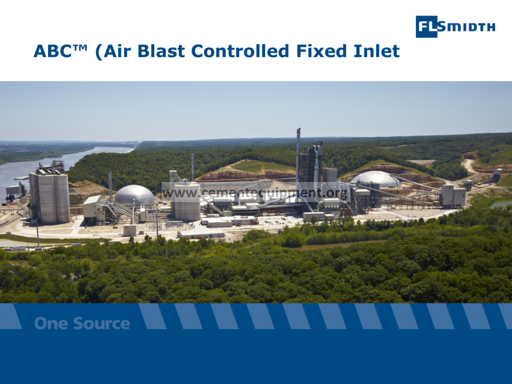
Cement Plant ABC: Complete Technical Dictionary & Guide
The ABC (Air Blast Controlled, Fixed Inlet) clinker cooler: design, air distribution, heat recovery, operation and maintenance of air blast grate coolers in cement plants.
The ABC cooler, shorthand for the Air Blast Controlled cooler with a fixed inlet section, is one of the classic grate cooler designs that powered the cement industry during the decades of rapid kiln capacity growth. It belongs to the family of air blast grate coolers in which clinker leaving the rotary kiln at a temperature above 1300°C is spread over a horizontal or slightly inclined grate and is rapidly quenched by a controlled flow of ambient air blown from below through fixed and reciprocating grate plates. The letter sequence ABC, which in the original FLS library documentation stands for Air Blast Controlled Fixed Inlet, describes a cooler whose inlet section is fixed rather than movable, allowing a compact, maintenance-friendly front end while the rest of the grate performs the conveying and cooling duty. This article provides a complete technical treatment of the ABC cooler: its place in clinker cooling history, the principles of air blast cooling, the mechanical arrangement of the fixed inlet, grate plate design, airflow and fan engineering, heat recovery for kiln combustion air and flash dryers, operation and control, maintenance planning, common failure modes, and the performance indicators used to benchmark cooler efficiency. It is written for plant engineers, process specialists and maintenance teams who work with air blast grate coolers and want a single, practical reference covering design intent, everyday operation and long-term care of the equipment.
1. The Role of the Clinker Cooler in the Cement Process
The clinker cooler is the final thermal machine of the pyroprocessing line and one of the most important units for overall plant efficiency. Its functions go far beyond simply reducing the temperature of the product so that it can be handled by conveyors and stored in silos. A well-designed and well-operated cooler performs five distinct duties at the same time.
- Rapid quenching of clinker: fast cooling preserves the quality of the alite and stabilizes the crystal structure of C3S, improving cement strength development, and avoids the slow-cooled clinker that produces large, poorly reactive crystals.
- Heat recovery: the secondary air recovered at the kiln hood and the tertiary air at the calciner carry back a large fraction of the heat stored in the hot clinker, directly reducing fuel consumption per tonne of clinker.
- Conveying: the cooler moves the hot clinker from the kiln discharge nose to the clinker crusher and from there to the transport system, acting as a mechanical conveyor operating at high temperature.
- Product conditioning: controlled cooling improves grindability, reduces the work index of the clinker, and produces a consistent product for the cement mill.
- Process stability: a stable cooler operation stabilizes kiln hood pressure, combustion air temperature and calciner firing conditions, which are the basis of smooth kiln control.
In the mass and energy balance of a modern dry process plant, the cooler represents the last point where sensible heat can be recovered from the solids before they leave the process. Recovery efficiency directly influences the thermal energy consumption of the line: a gain of a few percentage points in cooler efficiency translates into fuel savings measurable in megajoules per tonne of clinker, which on a 5000 t/d line means a meaningful reduction in annual fuel cost.
2. History and Development of Air Blast Grate Coolers
The air blast grate cooler evolved from the need to quench clinker quickly and recover heat in large quantities. The first grate coolers appeared in the early twentieth century, but the modern air blast design, in which air is forced through a perforated grate plate supporting a moving bed of clinker, became the industry standard after the Second World War. Several generations of design can be distinguished.
| Generation | Typical design features | Cooling air to clinker ratio | Operating era |
|---|---|---|---|
| First generation | Reciprocating grate plates, single compartment, simple air plenum chambers | 3.0 – 4.5 kg air/kg clinker | 1940s – 1950s |
| Second generation (ABC type) | Fixed inlet section, air blast controlled distribution, multiple compartments with adjustable dampers, recuperation zone separated from venting zone | 2.5 – 3.5 kg air/kg clinker | 1960s – 1980s |
| Third generation | Static aeration rails with variable air gaps, hydraulic drives, grate plates with integral aerators | 2.0 – 2.8 kg air/kg clinker | 1980s – 2000s |
| Fourth generation | Modular grate systems, walking floors, process automation with online temperature mapping | 1.8 – 2.4 kg air/kg clinker | 2000s to present |
The ABC cooler belongs to the second generation. Its defining innovation was the fixed inlet section: instead of making every grate section move, the first rows of grate plates near the kiln discharge were fixed, and the reciprocating movement started further down the grate. The fixed inlet provided several advantages that were significant in its era. It reduced the number of moving parts exposed to the highest temperatures and the largest thermal shocks, simplified the geometry of the kiln hood seal and the air plenums immediately under the inlet, and made it possible to direct the highest-pressure cooling air precisely at the point where the clinker bed is deepest and hottest.
3. Design Principle of the Air Blast Controlled Cooler
The name of the design contains its principle: the cooling air is blasted through the clinker bed under controlled conditions, and the control is achieved by dividing the grate area into compartments, each with its own air supply, pressure regulation and temperature monitoring. The clinker slides or is pushed over a perforated grate, while the air distribution system below the grate maintains a pressure high enough to overcome the resistance of the bed and the grate plate slots.
The term “air blast” emphasizes the role of the cooling air as both a heat sink and a conveying medium. Within each compartment, the air penetrates the bed from below, extracts heat from the clinker, and continues upward into the hood or the vent system. The clinker bed behaves like a packed bed heat exchanger, and the temperature profile across the bed thickness can be steep: the bottom layers in contact with the grate are cooled quickly, while the top layer remains hot until the air has passed through the whole depth. For this reason, the depth of the bed and the air pressure below the grate are the two variables that define the cooling result.
In the ABC arrangement, the fixed inlet rows are followed by movable rows that push the clinker forward. The moving grates, usually driven by an eccentric or hydraulic drive system, transport the material at a speed that is adjusted to keep the bed height constant at the inlet, which is the most reliable control variable for a cooler of this type. The clinker enters the cooler with a temperature of approximately 1350–1450°C and leaves it at 80–120°C in a well-run installation, after a residence time of roughly 20 to 60 minutes depending on cooler length and drive speed.
4. The Fixed Inlet Section
The fixed inlet is the signature feature of the ABC cooler and deserves a dedicated discussion. The inlet section is the zone of the highest thermal load. Clinker falling from the kiln nose cone forms a pile whose angle of repose depends on the particle size distribution and the clinker temperature, and the pile can reach a height of one meter or more. The falling material, often in large lumps and snowmen remnants, impacts the grate plates with considerable force, and the temperature shock when cool air hits hot clinker in the presence of dust is severe.
Designers of the ABC cooler solved the problem by fixing the first grate rows. The benefits are worth listing:
- Mechanical simplicity in the hottest zone: fixed plates have no drive elements, no seals sliding in hot dust, and no bearings near the kiln discharge.
- Higher static pressure capability: because the plates are fixed, the inlet plenum can be operated at higher pressure than movable sections, forcing air through the deep, hot pile where it is needed most.
- Better kiln hood sealing: the fixed inlet frame allows a clean transition between the kiln outlet seal and the first cooler rows, reducing false air ingress.
- Durability: the fixed plates can be made thicker and more massive than moving plates, giving them a longer life under the most demanding conditions.
Once the clinker pile at the inlet reaches its natural angle of repose, the deeper layers are cooled by the high-pressure air of the inlet plenum while the surface layer stays hot. The cooler drive is then used to pull the material forward, and the fixed inlet rows act as a distributor that feeds the moving grate at a more uniform depth than would otherwise be possible.
5. Grate Plates, Aeration and Pressure Zones
Grate plates are the working surface of the cooler and the most wear-critical components. In the ABC design they are cast iron or alloy steel plates with a series of slots, holes or louvres through which the air passes. Plate design must balance several conflicting requirements: sufficient open area to pass the required air at moderate pressure, narrow enough openings to prevent clinker fines from falling through or blocking the slots, mechanical strength to carry the weight of the bed plus impact loads, and resistance to abrasion, oxidation and thermal fatigue.
The open area of a typical air blast grate plate is 3 to 8 percent of the plate surface. With smaller openings, the air velocity through the slots increases, which helps to clean the openings and reduce penetration of fines, but the pressure drop rises. The common slot width for clinker service is 1.5 to 3 mm. The pressure below the grate is set per compartment: inlet compartments operate at 3500 to 6000 Pa, intermediate compartments at 2000 to 3500 Pa, and the last, cooler compartments at 1000 to 2000 Pa. The exact values depend on the bed depth and the clinker particle size; coarse, well-burned clinker with a narrow size range offers less resistance than dusty, poorly burned clinker.
Air distribution is controlled by dampers or by the fans themselves. The purpose of the compartmentalized control is to match the airflow to the local cooling demand. Hot, deep clinker near the inlet requires a high specific airflow, while the clinker at the discharge end, already cooled to a few hundred degrees, requires much less. Diverting air away from the discharge zone reduces the total excess air and increases the proportion of recuperation air, which is exactly what an efficient cooler should do.
6. Cooling Air Flows: Recuperation and Venting
The cooling air that enters the cooler splits into two streams of very different value. The recuperation stream consists of the secondary air drawn into the kiln through the hood and the tertiary air drawn to the calciner, both at temperatures of 700 to 950°C. This stream returns heat to the burning process. The venting stream, taken from the cooler compartments beyond the recuperation zone, is exhausted through a dust collection system after being used to cool the clinker; its heat is lost to the process unless it is recovered for drying or power generation.
The location of the recuperation zone is fixed by the cooler layout: the secondary air take-off is at the kiln hood, immediately after the cooler inlet, and the tertiary air duct connects to the cooler roof a short distance downstream. The air volumes are determined by the combustion demand of the kiln and the calciner: a kiln firing 4 tonnes per hour of fuel with a stoichiometric air demand of about 11.5 kg air per kg of fuel needs roughly 46,000 kg/h of combustion air, a figure that dwarfs the cooling airflow needed simply to quench the clinker.
Typical air quantities per tonne of clinker are summarized below.
| Air stream | Typical flow per tonne of clinker | Temperature | Use |
|---|---|---|---|
| Secondary air to kiln | 0.9 – 1.3 kg/kg clinker | 750 – 950°C | Kiln combustion |
| Tertiary air to calciner | 0.6 – 1.0 kg/kg clinker | 750 – 900°C | Calciner combustion |
| Venting air to dust collector | 1.0 – 2.2 kg/kg clinker | 250 – 350°C | Cooling, then dedusting |
| Total cooling air | 2.5 – 3.5 kg/kg clinker | — | — |
Higher recuperation temperatures are obtained when the specific airflow is low and the bed is deep, because the air has more time to approach the clinker temperature. There is, however, a practical limit: if the specific airflow becomes too low, the clinker at the discharge end is not cooled sufficiently, and the cooling curve becomes uneconomical because the fixed losses of the machine dominate. The optimum is found by balancing recuperation efficiency against clinker discharge temperature and fan power.
7. Fan System and Pressure Engineering
Every cooler compartment is served by a fan sized for the compartment pressure and flow. The fan system of an ABC cooler is the largest consumer of electrical energy in the cooling section, and its engineering deserves careful attention. The selection of fans must consider the worst realistic operating condition: high clinker production, fine dusty clinker, and deep beds create the highest resistance, and the fans must have sufficient pressure margin without being oversized for normal operation, since a fan running at constant speed against a reduced demand wastes energy.
The modern approach controls fan flow with variable speed drives or with inlet guide vanes. Because the resistance of the clinker bed varies continuously with kiln feed, temperature and clinker quality, constant speed fans with fixed dampers force the operator to choose between over-aeration and insufficient cooling. Variable speed control keeps the compartment pressure at the set point with the minimum fan energy, and automatic pressure control, where the compartment pressure is measured and the fan speed adjusted to hold it, is the standard method of stabilizing the bed.
An important detail in air blast coolers is the design of the plenum chambers below the grate. The plenum must distribute the air uniformly over the whole compartment width; a maldistribution leaves hot lanes in the clinker, causes uneven wear of the grate plates and creates zones where clinker sticks or snowballs form. Baffles, perforated distribution plates and a generous plenum volume are the standard remedies. In addition, the plenum must be sealed against false air ingress, since a leak below the grate draws cold air that bypasses the clinker and reduces both cooling and recuperation efficiency.
8. Heat Recovery and Cooler Efficiency
Cooler efficiency, defined as the ratio of heat recovered in the recuperation air to the total heat entering the cooler with the clinker, is the key performance indicator of the machine. A good second-generation air blast cooler recovers 60 to 70 percent of the clinker heat in the form of secondary and tertiary air, with the balance lost in the vented air, the shell losses and the sensible heat of the cooled clinker itself.
The heat entering the cooler with the clinker is significant. Clinker at 1400°C carries roughly 1400 to 1600 kJ per kg depending on the composition and the degree of burn. On a 5000 t/d line, this represents an energy flux of the order of 90 MW. Every percentage point of cooler efficiency therefore corresponds to roughly 0.9 MW of recoverable heat, or about 13 to 16 MJ of fuel energy per tonne of clinker when converted at typical kiln thermal efficiencies. The financial value of a 5 percent improvement in cooler efficiency on a modern line is easily one to two million USD per year in fuel savings at prevailing fuel prices, which is why cooler audits and cooler modernization are among the highest-return projects in the cement industry.
Methods to improve the heat recovery of an ABC cooler include: increasing the depth of the bed in the recuperation zone, lowering the specific cooling airflow by better bed distribution, improving the grate plate condition to avoid short-circuiting air through worn slots, reducing false air in the hood and the cooler, and upgrading the inlet section to a static aeration design with controlled air gaps. Each of these measures acts on the same principle: maximize the contact time between air and clinker at the highest clinker temperatures, and return the hottest possible air to the kiln.
9. Control and Instrumentation
Modern control of an air blast cooler is built on a hierarchy of measurements. The primary measurements are the grate drive speed, the under-grate pressures of the individual compartments, the hood pressure, the secondary and tertiary air temperatures, the clinker temperature at the cooler discharge, and the vent air temperature after the last compartment. Secondary measurements include the fan currents, the cooler roof temperatures, and, in modern installations, infrared temperature mapping of the grate surface.
The central control loop is the bed depth control: the cooler drive speed is adjusted so that the under-grate pressure in the first compartment, which is a direct measure of the bed resistance and therefore of the bed depth, is held at the set point. When kiln feed increases, the pressure rises and the drive speed is increased to keep the bed depth constant. A second layer of control trims the air distribution: compartment dampers or fan speeds are adjusted to maintain the desired temperature profile along the cooler, with the recuperation compartments holding the secondary and tertiary air temperatures at the target values required by the kiln and calciner burners.
An experienced operator reads the cooler as the mirror of the kiln. A sudden rise in under-grate pressure indicates a deeper bed, often caused by a kiln upset or by the arrival of a snowman; a falling secondary air temperature indicates that the bed in the recuperation zone is too thin or that the air distribution has shifted; a rising clinker discharge temperature indicates that the cooling capacity is insufficient, usually because of higher kiln production, coarser clinker, or a fan or damper malfunction. Instrumentation and operator training together turn these signals into stable, proactive control.
10. Operation of the ABC Cooler
Day-to-day operation of an air blast cooler is governed by a set of well-established practices. At startup, the cooler is operated with a thin bed and low airflow until the grate plates have reached their working temperature, to avoid thermal shock cracking of the cast plates. During normal operation, the operator maintains the bed depth set point, monitors the discharge temperature and the hood pressure, and checks the clinker for signs of under-cooling such as red lumps leaving the crusher.
The most common operational problems and their remedies are listed below.
| Problem | Typical symptom | Common causes | Remedy |
|---|---|---|---|
| Hot clinker at discharge | Clinker above 150°C, red spots after crusher | Thick bed, insufficient airflow, worn grate plates | Increase drive speed or airflow, repair plates |
| Snowmen at inlet | Pressure surge in inlet plenum, kiln hood pressure swings | Sticky clinker, alkalis, ring pieces from kiln | Shoot with air cannon, adjust burner, control alkalis |
| Uneven bed, hot lanes | Local hot spots on cooler roof | Air maldistribution, uneven clinker size | Rebalance compartments, repair plenums |
| Clinker dust blow-out | Fine dust lifted out of the bed, plugging of hood | Excessive airflow on fine clinker | Reduce airflow, improve clinker quality |
| Falling secondary air temperature | Kiln flame unstable, higher fuel | Thin bed, excess venting air | Increase bed depth, close vent dampers |
The discipline of recording cooler parameters on an hourly basis, and comparing them with the production rate and clinker quality, builds the data foundation for optimization. Many plants find that the cooler is the most neglected process unit, simply because its problems appear gradually; the discipline of reviewing cooler performance weekly, with the same rigor applied to the kiln, is one of the cheapest improvements available.
11. Maintenance of the ABC Cooler
Maintenance of an air blast cooler is dominated by the grate plates and the drive system. Grate plate wear is caused by abrasion of the clinker sliding over the surface, by oxidation at high temperature, and by the mechanical impact of lumps and snowmen. Plate life varies widely with service conditions: typical plate life is 12 to 24 months in the inlet zone, 24 to 36 months in the middle sections, and longer at the discharge end. Plates should be inspected during every scheduled stop, and the slot openings should be checked, since worn slots pass air in uncontrolled quantities and allow fines to fall into the plenum.
The drive system, whether eccentric with connecting rods or hydraulic with linear actuators, requires regular lubrication, alignment checks and wear measurement of the joints. A reciprocating grate that is out of alignment strains the plates and the support beams and accelerates wear of the seals between moving and fixed parts. The seals between the movable grate frames and the stationary side walls, which prevent air from short-circuiting around the bed, are another wear point that deserves regular inspection.
The crusher at the cooler discharge, usually a hammer crusher or a roller crusher, must be kept in good condition because oversized lumps block conveyors and reduce the efficiency of the transport system. Hammer wear, grate bar wear and tramp metal protection should be on the inspection list. Finally, the refractory lining of the hood and the cooler roof must be checked for cracks and missing bricks; roof failures allow cold false air into the recuperation zone and cost heat recovery efficiency as well as creating safety hazards.
12. Common Failure Modes and Root Cause Analysis
When an air blast cooler malfunctions, the symptoms usually appear first in the kiln. A cooler that cannot recover enough heat forces the kiln to compensate with more fuel; a cooler that overheats its discharge strand trips the conveyor protection; a cooler with false air upsets the hood pressure and destabilizes the flame. Root cause analysis of cooler problems should therefore begin with the kiln and the process, not with the mechanics.
- Snowmen formation at the cooler inlet is a process problem first: it is caused by sticky, alkali-rich clinker or by ring pieces from the kiln nose, and no amount of grate plate replacement will cure it. The remedy is in the raw mix and kiln operation, supported by air cannons.
- Premature grate plate wear usually indicates an air distribution problem: too much air on a thin bed accelerates erosion, while too little air leaves the plates hot and oxidized. Both point back to compartment control.
- Recurring seal failures indicate that the grate frame is being distorted, which points to the drive system or to thermal distortion of the support structure.
- Fan performance degradation is often caused by dust buildup on impeller blades or by damper wear; vibration analysis and current trend monitoring catch the problem early.
Documenting each failure with photographs, measurements and operating data, and reviewing the batch of evidence at the end of each campaign, converts the maintenance organization from a reactive one to an analytical one. This is particularly valuable for coolers of the second generation, where the machine has been in service for decades and the original design margins may no longer match the current production rates.
13. Performance Benchmarking of the Cooler
The standard metrics for benchmarking an air blast cooler are the specific cooling airflow, the secondary and tertiary air temperatures, the clinker discharge temperature, the recuperation efficiency, and the electrical energy consumption of the cooling fans. A typical performance test is carried out over 72 hours at stable kiln production, with the feed rate, fuel flows, cooler pressures and temperatures logged, and with clinker samples taken for temperature and size analysis.
The thermal audit uses the air balance of the cooler. The total air entering the cooler equals the sum of the recuperation air to the kiln and calciner, the venting air to the dust collector, the false air ingress, and any leakage through seals. Each stream is measured or calculated from fan data and duct instrumentation, and the resulting balance is checked against the clinker heat balance. The audit usually reveals that the venting stream is larger than the designers intended, because operators conservatively add airflow to protect the discharge temperature, and that a portion of the recuperation air is being lost to false air through worn seals and open doors. Correcting both findings is the essence of cooler optimization.
14. Upgrading the ABC Cooler
Many ABC coolers still in service have been upgraded to modern standards. The three most effective upgrades, in order of return on investment, are the installation of a static inlet section with controlled aeration, the automation of the compartment air control with variable speed fans, and the replacement of the venting system with a more efficient dust collector arrangement. A static inlet with adjustable air gaps increases recuperation temperature and reduces maintenance, the automation reduces fan energy and improves bed stability, and the venting upgrade reduces dust emissions and pressure losses.
Before any upgrade, a mass and energy audit of the existing cooler should be performed, because the design of the upgrade depends on the current performance baseline. The audit determines the actual cooling airflow, the recuperation temperatures, the vent temperatures, and the pressure profile along the grate, and this data defines the sizing of the new fans, dampers and aeration devices. Upgrading without a baseline is a common source of disappointment: the new equipment is installed, but the measured benefits are below expectation because the true performance limit of the existing machine was never established.
15. Safety in Cooler Operation and Maintenance
The cooler is a dangerous environment: hot clinker, high temperatures, rotating machinery, and dust combine to create hazards that must be managed with discipline. Lockout and tagout procedures for the grate drive, the crusher and the fans are mandatory before any entry. The plenum chambers below the grate must be purged and cooled before inspection, and the entry procedures must be supervised because the confined space rules apply to the plena and the dust collector ducts. Workers entering the cooler for plate replacement must wear full heat protection and be protected against falling clinker and collapsing beds; in practice, the bed is removed first and the work is performed on a cooled grate.
Burn injuries from hot clinker and hot air are the most common serious accidents in cooler work. The discharge strand and the crusher area must be protected with guards, and the operators must be trained to recognize the signs of a blocked crusher or a jammed drive before they attempt to clear it. Finally, the electrical equipment of the fans and drives, including the variable speed drives, must be maintained under the plant electrical safety rules, with arc flash protection for switchgear work.
16. Frequently Asked Questions
What does ABC stand for in the cement cooler context?
In the FLS library documentation, ABC stands for Air Blast Controlled Fixed Inlet. It describes a grate cooler with a fixed inlet section in which the cooling air is blasted through the clinker bed under compartment-controlled pressure, with the first grate rows kept stationary to withstand the highest thermal and impact loads at the kiln discharge.
Why is rapid clinker cooling important?
Rapid cooling locks the alite crystals in a fine, reactive state and prevents the transformation of C3S into the less reactive beta and gamma C2S forms. Well-quenched clinker grinds more easily and produces cement with better early strength and more consistent hydration behavior, and it also reduces the risk of dusting.
What is the difference between recuperation air and venting air?
Recuperation air is the cooling air drawn back into the kiln as secondary air and into the calciner as tertiary air, carrying heat recovered from the clinker. Venting air is the remaining cooling air that leaves the cooler after the recuperation zone and passes to the dust collector; its heat is not recovered in the process.
What is the normal clinker discharge temperature from a grate cooler?
In a well-operated air blast cooler, the clinker leaves at 80 to 120°C. Discharge temperatures above 150°C indicate insufficient cooling capacity, and temperatures above 200°C are a warning that the transport system and the silo are at risk of overheating.
What causes snowmen at the cooler inlet?
Snowmen are large clinker agglomerates that form at the cooler inlet when sticky, alkali-rich clinker or kiln ring pieces build up on the first grate rows. They block the airflow, disturb the bed and destabilize the kiln; they are cured by controlling the alkali and sulfur balance in the raw mix, adjusting the flame, and removing the build-ups with air cannons.
How can cooler heat recovery be improved?
By deepening the bed in the recuperation zone, reducing the specific cooling airflow, eliminating false air, repairing worn grate plates, and modernizing the inlet section. Each measure increases the air exit temperature and therefore the heat returned to the kiln and calciner.
Why do grate plates wear faster at the inlet?
The inlet section carries the hottest clinker, the deepest bed and the highest air velocities, and it receives the mechanical impact of lumps falling from the kiln nose. The combination of abrasion, oxidation and thermal fatigue makes the inlet plates the highest-wear components of the cooler.
What is the purpose of under-grate pressure control?
The under-grate pressure is a direct measure of the bed resistance and therefore of the bed depth. Holding the pressure at the set point by adjusting the grate drive speed keeps the bed depth constant, which stabilizes cooling, heat recovery and kiln operation regardless of feed variations.
17. Summary
The ABC air blast controlled cooler with its fixed inlet section is a classic of clinker cooling engineering, and its principles remain fully relevant today. The cooler’s duty is to quench the clinker, recover heat for the kiln and calciner, convey the product, and stabilize the whole pyroprocess, and each of these duties is achieved through controlled air blast cooling across a compartmented grate. The fixed inlet withstands the harshest conditions, the compartmented air system matches airflow to local demand, and the control system holds bed depth and air distribution on target. Maintenance focuses on grate plates, drives, seals and the crusher, while optimization work concentrates on heat recovery, false air elimination and the automation of the fan system. The cooler is the mirror of the kiln, and its performance is one of the most accessible levers for reducing fuel consumption and improving clinker quality in any cement plant.
Get this cement file + the full 931-file package
$249 — one-time purchase, instant download, lifetime access
This file is part of the Complete Cement Technical Package (931 files) available from cementequipment.org. Respective rights holders; library copy for the licensed single user.