Filters in Cement Plants: Bag & ESP Guide
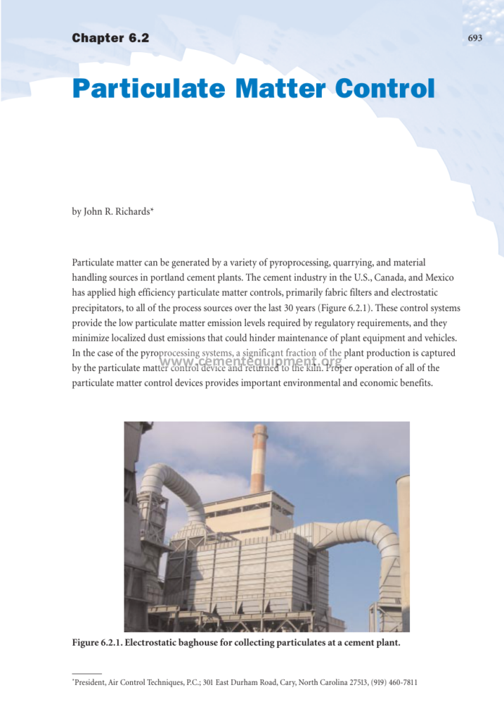
Particulate matter is generated by a variety of pyroprocessing, quarrying, and material handling sources in Portland cement plants, and filters are the equipment that keeps that particulate matter out of the atmosphere. The cement industry in the United States, Canada, and Mexico has applied high-efficiency particulate matter controls, primarily fabric filters and electrostatic precipitators, to all of the process sources for more than thirty years, and this practice has extended worldwide. These control systems provide the low particulate matter emission levels required by regulatory requirements, typically 10-20 mg/Nm3 on the kiln stack and similar or lower levels on mill vents, and they minimize localized dust emissions that could hinder maintenance of plant equipment and vehicles. In the case of the pyroprocessing systems, a significant fraction of plant production is captured by the particulate matter control device and returned to the kiln, so the filter is simultaneously an environmental device and a process recovery unit. This article provides a complete technical treatment of filters in the cement industry: the types of collection devices, the theory of fabric filtration and electrostatic collection, filter media selection, sizing and design calculations, installation, operation, monitoring, maintenance, troubleshooting, and the safety systems that protect both the equipment and the plant.
The Role of Filters in the Cement Plant
A modern cement plant operates between ten and fifty dust collection systems depending on its size and layout. The main kiln line filter handles the largest gas volume, up to a million normal cubic meters per hour on large lines, and defines the plant’s primary emission performance. Dedicated filters serve the clinker cooler, the raw mill circuit, the coal mill, the cement mills, and the crusher, and small cartridge collectors serve the silos, packers, transfer points, and workshops. The function is identical everywhere: separate particulate matter from a gas stream so that the gas can be released cleanly and the dust can be recovered.
The economic role of the filter is as important as its environmental role. On a 5000 t/d line, the kiln filter collects hundreds of tonnes of dust per day, all of which is returned to the process as raw material. A filter that operates poorly, through leaks, blinding, or high pressure drop, costs the plant in three ways: emission exceedances that attract fines and scrutiny, lost production or reduced kiln gas flow that limits output, and maintenance cost for bags, valves, and fans. Filter performance is therefore tracked as a production parameter, not merely as a compliance item, and the best-run plants integrate filter operation into their process control systems.
Types of Particulate Collection Devices
The cement industry uses four families of collection devices, each with a distinct operating principle and application niche. Gravity settling chambers and cyclones remove the coarse fractions at low efficiency; they are used as pre-collectors where the process benefits from separating coarse dust before the main collector. Electrostatic precipitators charge the particles and collect them on plates. Fabric filters, or baghouses, strain the particles out of the gas with a filter medium. Wet scrubbers contact the gas with a liquid, capturing particles and soluble gases simultaneously. The table below summarizes their place in the cement plant.
| Device | Collection principle | Typical efficiency | Typical outlet (mg/Nm3) | Cement plant application |
|---|---|---|---|---|
| Cyclone / multi-cyclone | Centrifugal separation | 60 – 90% | 150 – 400 | Pre-collector before filter, separator in mills |
| Fabric filter (baghouse) | Mechanical straining + cake filtration | > 99.9% | 5 – 20 | Kiln, cooler, all mill vents, silos, transfer points |
| Electrostatic precipitator | Corona charging + electrostatic attraction | 99 – 99.9% | 20 – 50 | Kiln gas, cooler (older installations) |
| Wet scrubber | Liquid contact, impaction + absorption | 95 – 99.5% | 10 – 50 | SO2 and combined dust capture on kiln gas |
| Cartridge collector | Cake filtration on pleated media | > 99.9% | 5 – 15 | Low-volume vents, silos, packers, workshops |
Fabric Filtration: Operating Principle
A fabric filter collects dust by passing the gas through a woven or felted medium, and the actual filtration surface quickly becomes the dust cake that builds on the fabric rather than the fabric itself. Fresh felt filters to a few microns at moderate efficiency, but within minutes the cake provides the fine filtration: the cake bridges the pores and captures particles down to sub-micron sizes, giving the mature filter its characteristic efficiency above 99.9 percent. The challenge of fabric filter design is to maintain the cake structure and remove it periodically without allowing the fines to penetrate the fabric, which is the phenomenon called depth loading.
Filter operation follows a continuous cycle of filtration and cleaning. During filtration, the cake thickens and the pressure drop rises. At a set pressure drop, or on a timed sequence, the cleaning system removes part of the cake. In a pulse-jet filter, a burst of compressed air at 5 to 8 bar, delivered through a venturi mounted in each bag top, creates a traveling wave that flexes the fabric and dislodges the cake into the hopper. In a reverse-air filter, the gas flow is reversed and directed inward through the fabric, collapsing the bags and releasing the cake. In a shaker filter, the bags are mechanically agitated. Each cleaning method suits a different media and duty: pulse-jet is the dominant technology in cement because it allows high air-to-cloth ratios and continuous operation at high temperature.
Filter Media: Fabrics, Felts, and Membranes
The filter medium is the heart of the baghouse, and media selection determines both emission performance and bag life. The cement industry uses a limited palette of media, selected on gas temperature, chemical environment, dust abrasiveness, and cleaning method. The table below lists the common media with their temperature limits and characteristics.
| Medium | Max continuous temp | Typical use | Remarks |
|---|---|---|---|
| Polypropylene | 90°C | Low-temperature mill vents, silos | Cheap, sensitive to heat |
| Polyester (PET) | 150°C | Raw mill, cement mill, crusher vents | Standard workhorse; hydrolyzes in moist acidic gas |
| Acrylic | 125°C | Moist or mildly acidic gas streams | Good hydrolysis resistance |
| Polyphenylene sulfide (PPS) | 190°C | Kiln gas, hot cooler gas | Good chemical resistance, sensitive to NOx at high temperature |
| Aramid | 200°C | Kiln gas, kiln-mill modes | Good balance of strength and temperature |
| Glass fiber | 260°C | Kiln gas on reverse-air systems | Heat resistant but brittle; needs surface treatment |
| PTFE (fiber or membrane) | 260°C | Kiln gas, demanding chemical or moisture duty | Excellent release and chemical resistance; highest cost |
| P84 (polyimide) | 240°C | Fine fume, kiln gas blends | High surface area for fine particle capture |
Modern practice increasingly uses surface filtration media: felts laminated with an expanded PTFE membrane or treated with microporous coatings that keep the dust on the surface, preventing depth loading and improving cake release. Surface filtration extends bag life, lowers pressure drop, and achieves the lowest outlet concentrations, and it is the standard choice for kiln and high-value applications. The medium is only as good as its installation, however: a misaligned bag, a torn gasket, or an over-tightened clamp can allow dust to pass or destroy the bag at the clamp line.
Filtration Theory: Mechanisms of Particle Capture
Understanding why a filter collects dust is the foundation for designing and operating it. A particle approaching a filter fiber or the surface of a dust cake is captured by one of four mechanisms. Inertial impaction collects the larger particles, those above roughly one micron, that cannot follow the gas streamlines around the fiber and instead strike it. Interception collects intermediate particles that follow the streamline but pass within one particle radius of the fiber surface and contact it. Diffusion collects the sub-micron particles, below about 0.3 microns, which undergo Brownian motion and randomly encounter the fiber. Electrostatic attraction adds to capture when either the particle or the fiber carries a charge. The efficiency minimum occurs in the transition region around 0.1 to 0.5 microns, where neither inertia nor diffusion is strong, and this is exactly the size range of the alkali fume that forms in the kiln system.
The practical consequences follow directly. The dust cake is the real filter: once the cake covers the fabric, the collection mechanism becomes sieving through the cake structure, and efficiency rises to 99.9 percent and above even for the finest fume. This is why cleaning must preserve part of the cake rather than remove it entirely, and why surface-filtration media that keep the cake on the surface outperform deep filtration felts that let fine dust penetrate and blind the fabric from within. It also explains the characteristic behavior of filters: the outlet concentration is lowest immediately after cleaning, when the residual cake has re-established, and highest during cleaning pulses, when a fraction of the dislodged cake can escape with the gas. Good filter design and operation manage these cleaning emissions to a few percent of the total, and the modern pulse-jet with off-line cleaning, where the compartment is isolated during the pulse, minimizes them almost to zero.
Baghouse Design: Sizing and Key Parameters
Baghouse sizing is governed by the air-to-cloth ratio, the gas flow divided by the fabric area, and by the system pressure drop budget. The air-to-cloth ratio determines both the footprint and the cleaning frequency: a higher ratio means a smaller filter but more frequent cleaning and higher pressure drop. Cement plant practice is conservative: kiln systems typically use 0.9 to 1.3 m3/m2/min on the gross cloth area to accommodate the dust load of 30 to 80 g/Nm3 and the kiln-mill mode transitions, while mill vents with lighter dust loads run at 1.5 to 2.5 m3/m2/min, and small silo and transfer collectors can run higher still.
The sizing calculation is straightforward: the gas flow in Nm3/h, converted to actual cubic meters per minute at the filter temperature, divided by the selected air-to-cloth ratio, gives the required cloth area. For a 700,000 Nm3/h kiln gas stream at 150°C and 1.1 m3/m2/min, the required area is on the order of 12,000 square meters, which translates to thousands of bags in multiple compartments. Compartmentation is essential for maintenance: each compartment is isolated by poppet valves so that bags can be changed and valves repaired while the rest of the filter continues to operate, with the remaining compartments carrying the extra load.
Pressure Drop and Its Management
The pressure drop across the filter is the operating parameter that ties together dust load, cleaning, and energy. Typical operating pressure drops range from 800 to 2000 Pa for kiln filters and 600 to 1500 Pa for mill vents, and the cleaning control set point is chosen to balance bag life and fan power. Cleaning too aggressively shortens bag life and re-entrains fine dust; cleaning too little lets the pressure drop climb, reducing gas flow and kiln production.
The key diagnostic is the pressure drop trend. A gradual rise usually indicates over-capacity operation, moisture in the gas, or a change in dust character; a sharp rise indicates blinding, a failed valve, or a water leak into the hopper; a sudden drop indicates a bag failure or a cleaning fault. The second key diagnostic is the compartment differential: the controller logs each compartment’s pressure drop, and a compartment that departs from its siblings is examined first. Instrumentation is therefore part of the filter specification: pressure transmitters per compartment, differential temperature across the filter, dust level indicators in the hoppers, and opacity or concentration measurement on the outlet.
Electrostatic Precipitators
The electrostatic precipitator remains an important technology in the cement industry, especially on kiln gas at older plants and on clinker coolers, where it operates without the media replacement cost of the baghouse. Its principle is elegant: a high-voltage corona between discharge electrodes and collecting plates charges the dust particles, which migrate to the plates under the electric field and are removed by rapping. Collection efficiency follows the Deutsch-Anderson equation and improves with larger specific collecting area, higher voltage, and finer particle removal being favored by good field control.
Two cement-specific sensitivities govern ESP performance. The first is dust resistivity: cement dust exhibits peak resistivity near 200°C, where collection efficiency falls; the resistivity drops at high temperature as conduction through the bulk increases, and at low temperature as condensed moisture conducts on the surface. The second is the CO interlock: the high-voltage fields can ignite flammable gas, so the ESP is tripped when CO exceeds its design level, typically around 1 percent, which means the precipitator stops collecting during combustion upsets. Modern ESPs for cement duty are engineered with improved gas distribution, high-frequency power supplies that track the process, and automatic voltage control, which allows them to meet 20-30 mg/Nm3, but they remain more sensitive to process variability than the fabric filter, which is the principal reason the industry is converting to baghouses.
Cartridge Filters and Special Applications
Beyond the main process filters, cement plants deploy hundreds of small collectors that keep fugitive dust at zero: silo top vent filters, packing machine dust collectors, crusher and screen extraction, workshop and laboratory collectors, and asphalt of compressed-air systems. The dominant technology is the cartridge collector, which uses pleated media in rigid cartridges instead of bags, achieving very high filtration area in a small footprint. Cartridge collectors are cleaned by pulse-jet in the same manner as baghouses and typically achieve 5-15 mg/Nm3.
Specialized duties include the coal mill filter, which handles a flammable dust and operates with the most rigorous safety engineering: CO and spark detection, explosion venting or suppression, isolation valves, and inerting connections. The laboratory or small process collectors handle variable dusts and are maintained with the same discipline as the main filters, because a leaking silo vent is as visible to the regulator as a leaking kiln filter, and far more visible to neighbors.
Safety Systems for Filter Installations
Filters handle hot gas, flammable dust, and pressurized air, and their safety engineering is a defined discipline. On kiln and preheater filters, the primary hazard is fire from burning dust: hot clinker dust can carry sparks, and a smoldering dust deposit in a hopper can develop into a hopper fire that is extremely difficult to extinguish. The defenses are spark traps on the inlet, temperature monitoring across the filter, CO monitoring, fire detection in hoppers and ducts, and nitrogen or steam injection points for extinguishing. Hopper fires are fought by sealing the hopper and introducing inert gas, never by opening it to atmosphere.
Explosion protection applies where flammable dust or gas can accumulate. Coal mill filters are designed with explosion relief panels, isolation dampers, and inerting, and the kiln gas stream is monitored for CO to protect both ESPs and baghouses from flammable mixtures of CO and air. Electrical equipment in filter areas follows the appropriate hazardous-area classification. Access for maintenance is controlled by lockout and tagout, and entry into hoppers, housings, and ducts is governed by confined space procedures, because the dust inside a hopper is fluid and can engulf a worker in seconds.
Monitoring, Leak Detection, and Emission Verification
Filter performance is verified at three levels. The regulatory level uses continuous emission monitors for dust on the main stacks, plus periodic reference measurements; the operating level uses pressure drop, hopper level, and outlet opacity or tribo-electric monitors on the principal collectors; the maintenance level uses compartment differentials and visual inspection. Broken bag detection is a specific skill: a single failed bag on a 2000-bag filter raises the outlet concentration noticeably but not alarmingly, so plants use triboelectric or light-scattering monitors per compartment and scheduled leak-testing campaigns with dust or fluorescent tracers.
The emission verification program is anchored in the reference methods: isokinetic sampling with gravimetric determination of the collected dust, as defined by standards such as EN 13284 and EPA Method 5 for filterable particulate matter. The relationship between the continuous monitor reading and the reference measurement is established at certification and re-verified periodically, because the permit is enforced against the reference method while the daily operation uses the continuous signal. Filter management thus closes the loop: continuous signals detect deterioration, leak testing locates it, bag replacement corrects it, and reference testing proves it to the regulator.
Filter Maintenance: The Lifeline of Compliance
Filter maintenance is the discipline that separates plants that meet their emission limits from plants that report exceedances. The maintenance program covers the medium, the cleaning system, the valves, the fan, and the structure. Bag life on kiln duty is typically 3 to 6 years with proper operation; on mill vents it is often longer, and on demanding hot-gas or corrosive duty it can be shorter. The program elements are: scheduled inspection of bags, cages, clamps, and gaskets; pulse valve testing and compressed air quality control, because moisture and oil in the pulse air destroy bags quickly; differential pressure review per compartment; hopper level management to prevent dust packing and fires; and structural inspection of the housing, ducts, and supports for corrosion and abrasion.
- Maintain a bag inventory with the exact media specification and a defined storage standard.
- Inspect every new bag installation: clamp torque, bag verticality, cage condition, seal integrity.
- Track bag life and failure modes by compartment and position; repeated failures at one position indicate a structural cause.
- Test pulse valves on a schedule and calibrate the cleaning sequence to the actual pressure drop behavior.
- Dry and filter the pulse air; install coalescing filters and dew-point monitoring on the air system.
- Conduct annual leak detection and reference emission tests to verify the whole system.
- Document all maintenance in the filter log that connects maintenance events to emission data.
The economics favor this discipline: the cost of a bag change campaign on a kiln filter, including the labor and the production impact, is a major event, and a well-run program extends bag life, avoids emergency interventions, and keeps the emission record clean.
Troubleshooting Common Filter Problems
Filter problems announce themselves through a small set of symptoms, and the troubleshooting table below links the symptom to its most likely causes and remedies. The guiding rule is to diagnose from the data: pressure drop, temperature, and emission trends point to the subsystem before anyone climbs the structure.
| Symptom | Likely cause | Remedy |
|---|---|---|
| Gradual pressure drop rise | Moisture in gas, over-frequency cleaning off, dust character change, media aging | Check dew point and mode transitions; adjust cleaning; review media life |
| Sudden pressure drop drop | Bag failure, hopper discharge fault, cleaning fault | Locate compartment by differential; inspect and replace bags |
| Rising outlet concentration | Bag leaks, seal failures, gasket damage | Leak test per compartment; repair or replace |
| Blinding (irreversible pressure rise) | Condensation, oil in pulse air, resinous or sticky dust | Dry and heat the gas or pulse air; surface media; replacement campaign |
| Hopper level alarms | Discharge screw or rotary valve fault | Inspect discharge; clear bridging |
| Emission spikes during mill mode changes | Temperature or moisture transient exceeding media limits | Review mode-change procedure; adjust bypass or cleaning during transition |
| Bag wear at one position | Cage damage, clamp misalignment, structural deflection | Correct the structural or installation cause, not just the bag |
Filter Selection: A Decision Framework
Selecting the right filter for a given service requires balancing emission target, gas conditions, dust properties, space, and economics. The decision framework used by engineering groups considers the following elements in order: the required outlet concentration, because baghouses are the default where 10-20 mg/Nm3 or lower must be guaranteed; the gas temperature and its variability, which fixes the media family; the moisture and dew point, which determine whether condensation protection and heated housings are needed; the dust load and particle size, which fix the air-to-cloth ratio; the available space and pressure drop budget, which size the unit; and the life-cycle cost, including media replacement, fan energy, and availability.
For retrofit decisions, the comparison between upgrading an ESP and converting to a baghouse is the classic case. ESP upgrades, adding fields or upgrading power supplies, preserve the existing structure and can reach 20-30 mg/Nm3, but they cannot guarantee performance during process upsets. A conversion to a baghouse, placing the fabric filter downstream of the existing ESP or replacing it entirely, guarantees the lowest emissions and simplifies operation, at the cost of media replacement and pressure drop. In practice, most plants with tightening limits choose the baghouse, and the ESP-to-baghouse conversion is one of the most common environmental capital projects in the industry.
Filter Operation Across the Kiln-Mill Modes
The kiln line filter operates across a changing gas environment as the plant switches between the mill-on and mill-off modes, and the operating procedure must manage the transitions. In the mill-on mode, kiln gas passes through the raw mill, dropping from 300-350°C to 90-120°C, gaining moisture from the raw material, and carrying mill dust; the filter then handles a large, cool, moist, SO2-lean gas stream. In the mill-off mode, the full hot gas stream, at higher temperature and higher dust load, goes directly to the filter. The transition itself is the dangerous period: the temperature crosses the dew point of the moist gas, and a cold filter exposed to moist gas blinds within minutes.
The operating rules follow from this. The filter is pre-heated, by running the gas through it at controlled temperature, before the raw mill is started; the cleaning sequence is adjusted for the mode, because the cooler moist gas produces a stickier cake; and the fan is controlled to keep the gas flow and pressure drop within the design envelope. Mode changes are logged with the filter data, because most filter upsets in cement plants can be traced to a mode transition performed too quickly. This is the practical meaning of integrating the filter into the process control philosophy: the filter is not an appendage at the end of the duct, but an operating unit whose condition must be managed in the same control room as the kiln.
Frequently Asked Questions
What is the difference between a baghouse and a cartridge filter?
A baghouse uses cylindrical fabric bags, while a cartridge filter uses pleated rigid cartridges. Cartridges pack more area per volume and suit lower-volume, lighter-load duties such as silo vents; baghouses handle the large gas volumes and high dust loads of kilns and mills.
What emission level can a modern fabric filter achieve?
Well-operated fabric filters achieve 5-10 mg/Nm3 on kiln gas and similar levels on mill vents, and the industry standard for new designs is to guarantee 10 mg/Nm3 or less. Permit limits of 10-20 mg/Nm3 are met with comfortable margin.
How long do filter bags last in cement plants?
On kiln duty, bag life is typically 3-6 years with proper operation and media selection; on mill vents and low-temperature duties, 5-10 years is common. Moisture, high temperature, and aggressive cleaning shorten life.
Why is the air-to-cloth ratio important?
It determines filter size, cleaning frequency, and pressure drop. Too high a ratio means more cleaning, shorter bag life, and higher energy; too low a ratio means an oversized, expensive filter.
Why are electrostatic precipitators being replaced by baghouses?
ESPs are sensitive to dust resistivity and must trip on high CO, so they cannot guarantee performance during process variability. Baghouses achieve lower emissions regardless of dust conditions, which is decisive as limits tighten.
What causes a hopper fire in a filter?
Smoldering hot dust, typically from kiln operation or a spark source, accumulating in a hopper where air flow stops. Prevention is temperature and CO monitoring; response is sealing the hopper and inerting with nitrogen or steam.
How do I detect a broken bag?
Through outlet dust monitors, compartment differential pressure, and leak-testing with tracer dust or fluorescent powder. Per-compartment triboelectric monitors give the fastest indication of a failing compartment.
Summary
Filters are the defining environmental technology of the cement industry. They operate on every gas stream in the plant, from the million-cubic-meter kiln line to the smallest silo vent, and they combine two functions that are inseparable in practice: they keep the plant’s emissions at 10-20 mg/Nm3 and below, and they return hundreds of tonnes per day of process dust to production. The technology is mature and the choice is clear for most services: fabric filtration with pulse-jet cleaning and surface-filtration media dominates new installations because it guarantees the lowest emissions under all process conditions, while electrostatic precipitators remain in service where their economics still work, and cyclones and scrubbers fill their specific niches. The operational reality is that filter performance is determined as much by maintenance and operating procedure as by design: media selection matched to temperature and moisture, disciplined cleaning control, per-compartment monitoring, leak detection, and safety systems for fire and explosion are the elements of a complete filter management program. This article has provided the complete technical foundation for the selection, design, operation, and maintenance of filters in cement plants.
Get this cement file + the full 931-file package
$249.99 — one-time purchase, instant download, lifetime access
This file is part of the Complete Cement Technical Package (931 files) available from cementequipment.org. Respective rights holders; library copy for the licensed single user.