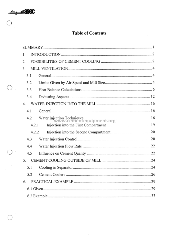
Mill Ventilation and Cement Cooling: Complete Guide
Mill ventilation and cement cooling is the discipline that the grinding manuals treat in a page and the plant discovers in the tonnage: the air that flows through the mill shell removes the heat of the grinding, carries the fine particles to the separator, controls the coating on the balls and the liners, and shapes the temperature of the finished cement: the mill without the ventilation is a machine that throttles itself: the right ventilation is measured in meters per second of the air velocity, and the modern file of the package carries the full arithmetic of the air and the water.
The Complete Cement Technical Package includes 931 cement-industry files covering books, courses, Excel tools and presentations. The $249 one-time package includes this ventilation and cooling guide with heat-balance material, fan/airflow references and cooling-system guidance, with instant download access immediately after payment.
Grinding converts much of the supplied electrical energy into heat, but the useful-fracture fraction and the distribution of heat among product, shell, gas and auxiliaries depend on the mill and the operating point. Ventilation and any approved cooling system should therefore be evaluated through a measured heat balance rather than a universal efficiency percentage.
1. Why the Mill Must Be Ventilated: The Four Duties of the Air
The ventilation air of the ball mill is not a luxury but the working medium of the process, with four separate duties:
- The heat removal: grinding, hot feed and circulating material add heat to the circuit. Ventilation removes part of that heat, but the required duty should be calculated from the actual mill power, mass flow and heat balance rather than a generic temperature outcome.
- The particle transport: the air velocity near the mill outlet lifts the fine particles out of the mill into the separator circuit: the classification depends on this pneumatic transport: the too-slow air leaves the fines circulating inside the mill:
- The coating control: the heat softens the cement particles and they coat the grinding media and the liner plates: the coating cushions the impact, reduces the grinding efficiency and raises the power per ton: the cool air keeps the surfaces clean:
- The gypsum dehydration and the moisture removal: the air removes the moisture of the feed and carries the evaporated water out of the mill: the temperature inside the mill controls the dehydration of the gypsum, which drives the setting of the cement:
The four duties set the numbers of the ventilation: the air must be fast enough to carry the fines, slow enough not to lift the coarse particles, and cool enough to control the temperature: the file defines the operating window of the mill ventilation with the velocity and the volume ranges that the industry practice has established.
2. Airflow and Velocity: Establishing the Operating Envelope
Ventilation values must be derived for the actual mill and circuit rather than copied from one generic table.
| Parameter | How to establish it |
|---|---|
| Mill gas velocity | Measured gas flow divided by effective free area, checked against OEM/design and product behavior |
| Ventilation volume | Heat, drying, transport, pressure and dust-collection requirements |
| Mill inlet gas temperature | Cooling or drying duty, feed condition and equipment limits |
| Mill outlet temperature | Plant-validated cement quality, sulfate system, filter and equipment operating limits |
- The volume basis: required gas flow should be derived from heat removal, drying, transport, pressure and dust-collection duties. Motor power or throughput alone is not sufficient to size the ventilation system.
- The velocity check: calculate gas velocity from measured flow and the effective free area of the operating mill, then compare it with the OEM/design basis and product behavior. Do not infer a universal particle carry-over percentage from one velocity range.
- The raw-mill difference: raw mills with drying duty require a separate heat-and-mass balance based on feed moisture, gas source and outlet-moisture target. The applicable velocity and temperature range is equipment-specific.
- The measurement: the volume is measured at the mill outlet duct and the filter: the operating venting curve of the fan, the damper positions and the pressure readings give the plant the continuous picture:
Loss of throughput can be associated with reduced ventilation, but it can also come from feed, media, separator, diaphragm or mechanical changes. Use measured flow, pressure, temperature, fan condition, separator performance and product quality to diagnose the cause. Set airflow-audit frequency from performance drift and maintenance history rather than a fixed monthly schedule.
3. The Heat Balance of the Mill: The Bookkeeping of the Kilowatts
The heat balance of the mill is the accounting of where the energy comes from and where it goes:
- The heat input: the mill drive power (the largest input, 3,000 to 8,000 kW), the heat of the material entering (the clinker at 60 to 120 degrees from the cooler or the storage), the grinding aid and the ventilation air temperature:
- The heat output: heat leaves through the product, exhaust gas, evaporation, shell and other losses. The percentage split is mill-specific and should be calculated from measured mass flows and temperatures rather than assigned from fixed ranges.
- The balance equation: the sum of the inputs equals the sum of the outputs plus the changes of the stored heat: the plant performs the balance in the steady state and verifies the accuracy with the measured temperatures and the air volumes:
- The use of the balance: the heat balance helps distinguish hot feed, insufficient gas flow, filter/fan limitations and the capacity of any approved cooling system. It should identify the verified limiting duty before an operator changes setpoints.
Feed temperature can be a significant heat input. Quantify its effect from the actual feed mass flow, temperature and specific heat, then compare operational or storage options on that measured basis rather than assuming a fixed temperature-to-output relationship.
4. The Water Injection: The Internal Cooling of the Mill
The water injection is the second exit of the heat, and the fine spray inside the mill uses the latent heat of the evaporation:
- The principle: where approved by the mill design, atomized water can remove heat by evaporation. The required rate must be calculated from the heat balance and kept within the system’s evaporation, atomization and cement-quality limits rather than a universal litre-per-ton figure.
- The equipment: use the installed system’s specified lance/nozzle arrangement, atomization method, flow control and interlocks. Start/stop logic must follow the validated plant control strategy rather than a generic temperature setpoint.
- The limits: the water must evaporate completely before the material leaves the mill: the residual moisture raises the cement temperature of the dehydration profile and spoils the setting: the injection above the evaporation capacity floods the mill and blocks the diaphragm:
- The quality control: the injected water is quality-monitored: the lift of the water to the boiling is complete only with the fine atomization, and the plant verifies the mill outlet temperature response as the control quality:
Where installed, water injection can provide useful evaporative cooling, but it should not mask inadequate airflow, excessive feed temperature, filter restriction or other root causes. Use the heat balance and cement-quality response to determine whether and how much water is appropriate.
5. The Mill Outlet Temperature Control: The Loop that Protects the Cement
The mill outlet temperature is the process instrument that the operator watches with the discipline of the kiln temperature:
- The target window: establish the acceptable outlet-temperature range from the plant’s actual sulfate source, moisture, residence time, cement quality and equipment limits. Do not apply one universal 95–115 °C window or a single dehydration threshold to every cement.
- The control variables: the ventilation volume (the primary knob), the water injection (the secondary), the feed rate and the clinker temperature: the operator balances the knobs against the outlet temperature and the mill load:
- The seasonal effect: ambient and clinker temperature can change the heat load. Quantify the effect from measured feed temperature and the heat balance before changing feed rate or cooling settings.
- The sulfate behavior: dehydration depends on temperature history, residence time, moisture and sulfate source. Validate the operating window with the plant’s setting, strength and other required quality tests at an interval appropriate to quality-control needs.
The temperature control is the guardian of the cement quality: the plants mark the outlet temperature of every shift in the log with the same care as the kiln parameters: the file provides the control philosophy and the alarm settings of the mill temperature, and the operator cards of the summer and the winter operation.
6. The Ventilation Air Cleaning: The Filters of the Mill Circuit
The ventilation air that leaves the mill carries the cement dust and must be cleaned before the atmosphere:
- The dust load: inlet loading depends on the circuit and collection arrangement, while outlet emissions must follow the applicable environmental permit and the actual collector capability. Use measured loading and regulatory limits rather than generic concentration ranges.
- The filter types: bag-filter media, air-to-cloth ratio and cleaning method should be selected from gas temperature, dust properties, loading and collector/OEM design rather than a universal cement-service ratio.
- The hybrid arrangements: the mill ventilation air returns through the filter into the separator or the direct separate clean-up: the combined systems treat the separator vent and the mill vent in the one filter house:
- The explosion protection: combustible-fuel grinding requires a dedicated hazard-management system covering inerting, gas monitoring, isolation and explosion protection. Requirements must follow the fuel-mill OEM, site hazard analysis and applicable combustible-dust safety standards; do not infer them from ordinary cement-mill ventilation.
- The filter maintenance: the blocked bags starve the ventilation and the mill at once: the differential pressure of the filter is the indicator, and the bag change is scheduled against the pressure rise:
The ventilation chain ends at the filter, and the filter is the weakest link of the chain: the plant that watches the filter differential pressure watches the mill ventilation: the returned dust is the product of the mill, and its recirculation to the feed or the separator completes the material loop: the file covers the full filter sizing and the operation of the mill vent cleaning.
7. The Cement Cooling Outside the Mill: The Coolers and the Storage
The mill outlet temperature control holds the process; the cement cooling beyond the mill protects the logistics and the market:
- The cement cooler: where downstream cooling is required, equipment is selected from product flow, inlet temperature, target storage/packing condition and available utilities. The target temperature should come from product and equipment requirements rather than a universal 60–70 °C value.
- The silo issues: the warm cement in the silo continues to hydrate slowly, cures and forms the ratholes and the lumps: the silo discharge problems correlate directly with the cement temperature: the cool cement is the first preventive measure of the storage discipline:
- The packing temperature: acceptable cement temperature at packing depends on packer design, bag material, product requirements and downstream handling. Use equipment and quality limits rather than a universal 70–80 °C threshold.
- The summer dispatch: the bagged cement in the transport cools slowly: the dispatch plans consider the cement temperature at the packer as a quality gate in the hot climates: the file gives the acceptable temperatures per channel:
The cement cooling is the quality link between the mill and the customer: the cool, dry cement stores, conveys and packs reliably, and the plant that controls the temperature at the mill and the cooler protects the whole dispatch chain: the file covers the cooler selection and the storage planning with the seasonal numbers.
8. The Ventilation of the Vertical Roller Mill: The Different Balance
The vertical roller mill ventilates with a completely different philosophy: the air is the grinding medium itself:
- The air as the classifier medium: in the VRM the air stream lifts the ground material from the table into the internal separator: the air flow is the primary control of the classification, and the volume per ton is an order of magnitude higher than the ball mill:
- The gas balance: VRM gas flow and throat conditions are determined by feed moisture, drying duty, pneumatic transport, pressure drop and separator requirements. Use the specific VRM OEM process map rather than generic material-to-gas or throat-velocity ranges.
- The temperature control: VRM outlet temperature should follow the product, drying, sulfate and equipment requirements of that specific application. Do not transfer a ball-mill temperature window directly to a VRM.
- The external air circuit: fan and gas-circuit power can be a significant part of VRM station energy, but the share depends on the system and operating point. Benchmark measured auxiliary kWh/t rather than a universal percentage.
The VRM ventilation is inseparable from the grinding itself: the air flow settings are the product fineness settings, and the gas circuit is the energy profile of the machine: the file translates the classical mill ventilation knowledge into the VRM vocabulary and documents the air circuit design of the vertical systems.
9. The Measurement and the Control of the Ventilation: The Instruments
The ventilation cannot be managed without the measurement, and the instrument list of the mill circuit is the file’s practical chapter:
- The volume measurement: the pitot traverses in the ducts, the venturi and the orifice plates on the clean air side, and the calibrated fan curves: the permanent flow elements give the continuous volume signals:
- The pressure measurements: the mill inlet pressure, the mill outlet pressure and the filter differential pressure: the pressure pattern across the circuit is the daily snapshot of the ventilation health:
- The temperature measurements: the mill outlet temperature, the bearing temperatures and the ventilation air temperatures: the temperature trend of the outlet is the control instrument of the mill cooling:
- The humidity measurement: the moisture of the vent air and the dew point readings verify the complete evaporation of the injected water and the drying duty in the raw service:
- The automated control: the modern plants close the loop: the outlet temperature to the water injection and the vent damper, the filter pressure to the cleaning cycle: the control architecture of the mill ventilation is documented in the file with the loop diagrams:
The instrument chain of the ventilation is the sensor system of the grinding department: the plant with the accurate volumes and the reliable temperatures operates its mills at the design point, while the plant that guesses the air operates at the mercy of the season: the file lists the instrument specifications and the calibration schedule of the mill circuit.
10. The Troubleshooting of the Ventilation and the Cooling Problems
The field experience of the mill ventilation reduces to a short list of the recurring problems and their signatures:
| Symptom | First checks | Possible causes | Next action |
|---|---|---|---|
| Mill outlet temperature rising | Feed temperature, airflow, pressure profile, filter ΔP, heat balance | Hotter feed, reduced gas flow, restriction, higher load or cooling-system issue | Correct the verified cause and change one approved parameter at a time |
| Temperature unusually low | Feed condition, airflow, false air, water-injection status | Cold feed, excessive false air/ventilation or incorrect cooling command | Return the circuit toward the validated baseline; do not blindly reduce airflow |
| Heavy coating | Temperature, moisture, ventilation, grinding aid, feed chemistry | Condensation, wetting, hot/sticky material or chemistry change | Diagnose from measured data before changing ventilation or water |
| Diaphragm restriction | Mill ΔP, material flow, moisture history | Build-up, debris or wetting | Plan internal inspection/cleaning under approved shutdown, isolation and lockout/tagout |
| Filter ΔP rising | Gas flow, bag-cleaning system, humidity, hopper/discharge condition | Dust loading, wet bags, cleaning fault or flow change | Diagnose collector condition before bag replacement |
| Separator/circuit performance falls | Separator settings, feed/reject PSD, airflow, mill discharge | Classifier, mill or ventilation change | Use the complete circuit balance before changing fan or separator speed |
- The blocked diaphragm: the moisture, the cement coating and the debris progressively close the diaphragm slots: the mill loses the throughput and the temperature rises: the diaphragm cleaning is a scheduled maintenance item with the season patterns:
- The clipped beds and the dampers: the fan wears, the damper sticks and the bags block: the ventilation volume falls without any alarm except the temperature: the monthly volume check is the remedy:
- The summer heat load: the ambient air at 40 degrees enters the mill warmer: the venting capacity for the summer conditions is calculated at the design stage, and the plants in the hot climates pre-cool the ventilation air or increase the water injection:
The troubleshooting tables of the file convert the symptoms into the actions: the plant that reads its own mill the way this section teaches avoids the majority of the grinding downtime, because most of the mill problems are heat and air problems before they become the mechanical failures.
11. The Seasonal Operation: The Summer and the Winter of the Ventilation
The ventilation and the cooling of the mill follow the seasons, and the seasonal operation is the first experience every grinding plant shares:
- The summer profile: higher ambient and feed temperatures increase cooling duty. Use the seasonal heat balance and equipment limits to determine the required ventilation, cooling and production response; do not assume maximum airflow or full water injection is always correct.
- The winter profile: colder gas and surfaces can reduce temperature but may increase condensation risk. Use measured dew point, false air, heat balance and quality results rather than automatically throttling ventilation.
- The transition management: the spring and the autumn shifts: the operators adjust the ventilation and the water through the transition weeks: the written transition procedures and the seasonal checklists of the file guide the changeover without the quality excursions:
- The clinker storage strategy: the seasonal rotation of the clinker stock: the summer uses the cool stored clinker, the winter the fresh: the stock management of the clinker is the seasonal cooling lever of the plant: the file covers the clinker storage yard design and the rotation planning:
The seasonal operation of the file is the practical calendar of the grinding department: the ventilation, the water and the clinker stock are managed against the climate, and the plant that plans the seasons runs the mills at the stable quality throughout the year: the seasonal discipline is the year-round version of the mill knowledge.
12. The Energy Economics of the Ventilation: The Air Costs Money
The ventilation is free in the process sense and expensive in the accounting sense: the air moving through the mill costs the fan power continuously:
- The fan power: quantify fan and collector energy from measured kW and gas duty. The share of grinding-station power and the required flow vary by circuit, so benchmark the actual fan operating point and kWh/t instead of generic percentages and flow ranges.
- The system resistance: the filter bags, the ducts and the dampers create the resistance: the clogged filters raise the resistance and the fan power at the same volume: the filter pressure management is the energy management of the ventilation: the file documents the resistance audit of the vent system:
- The secondary air utilization: the mill ventilation air, cleaned and warm, is reused in the separator and the process where the layout allows: the air circuits of the modern plants integrate the ventilation and the classification air streams, saving the separate fan duties:
- The optimization levers: the fan speed control against the damper throttling, the duct layout with the low pressure losses and the filter selection with the low resistance: the ventilation energy projects of the file rank among the fastest payback items of the grinding department:
The energy economics of the ventilation are the hidden cost of the air: the plant that manages the ventilation volumes, the filter resistance and the fan efficiencies controls the ventilation expense dollar by dollar: the file’s ventilation energy audit converts the air system into the measured, optimized utility of the grinding department.
13. The Advanced Cooling: The Fine Control and the Quality Integration
The modern mills integrate the temperature measurement and the cooling control with the product quality in the ways the older plants never attempted:
- The model-based temperature control: the heat balance models of the mill run online: the model predictions of the outlet temperature with the clinker temperature and the moisture inputs: the model-based control anticipates the disturbances ahead of the thermostat response: the file documents the model based loop configurations:
- The quality integration: the mill temperature, the gypsum state and the cement setting are linked: the online measurement of the temperature and the sulfate dissolution integrate the cooling control with the quality targets: the plants with the online quality analyzers close the cooling loop on the product state:
- The energy recovery: the waste heat of the mill cooling and the ventilation air: the recovered heat serves the winter process heating and the clinker drying: the energy integration projects of the modern plants reduce the net thermal demand of the sections:
- The digital monitoring: the continuous trending of the temperatures, the air flows and the cooling water rates in the historian: the digital monitoring detects the slow degradation and the drift long before the symptoms: the predictive maintenance of the ventilation and the cooling equipment follows the data:
The advanced cooling chapter of the file looks forward: the models, the quality integration and the energy recovery extend the classical ventilation knowledge into the modern process control: the engineer who combines the classical air discipline with the modern control tools operates the grinding at the frontier of the efficiency: the ventilation and the cooling knowledge completes with the future.
14. The Ventilation of the Raw Mills and the Drying Systems: The Hot Gas Circuit
The raw mills carry the same ventilation physics with the reversed temperature logic: the air heats instead of cools, and the drying duty dominates:
- The hot-gas sources: kiln/preheater exhaust or a dedicated hot-gas generator may supply raw-mill drying. Required inlet gas temperature depends on feed moisture, gas composition, heat source and equipment limits and must be calculated from the drying balance.
- The raw-mill gas volume: required gas flow depends on drying load, pneumatic transport, pressure drop and classifier duty. Use the actual mass/heat balance and OEM design rather than a generic m³/h range or fixed multiple of finish-mill ventilation.
- The drying loops: control drying from feed moisture, outlet moisture, gas flow/temperature and equipment constraints. Representative feed-moisture data—not a generic limestone/marl range—should drive the gas requirement calculation.
- The dew point protection: the gas leaving the raw mill cools in the filter: the condensation below the dew point cakes the filter bags and corrodes the ducts: the filter pre-heating and the temperature control of the gas circuit protect the system: the dew point management is the winter discipline of the raw mills:
- The interrelation with the kiln: the kiln gas availability and the raw mill operation are coupled in the bypass arrangements: the kiln stops leave the raw mill on the hot gas generators: the gas circuit integration of the plant is the system design of the raw section:
The raw mill ventilation is the mirror of the finish mill knowledge: the same volumes and velocities serve the opposite temperature goals, and the drying adds the moisture dimension: the file’s raw mill chapter completes the ventilation guide with the hot gas circuit: the engineer who masters both ends of the mill ventilation, the cooling of the finish and the drying of the raw, holds the complete air discipline of the grinding departments.
15. Practical Mill Ventilation and Cooling Audit
- Define the product, throughput, mill configuration and stable operating baseline.
- Measure gas flow and calculate velocity from the effective free area; record the measurement uncertainty.
- Record mill inlet/outlet pressure, fan pressure, filter differential pressure and damper/VFD positions.
- Record feed, mill-outlet and product temperatures together with feed moisture and gas humidity/dew point.
- Build a heat-and-mass balance before changing ventilation or any approved cooling system.
- Quantify false air using an approved leak-test or gas-balance method and compare with the design baseline.
- Compare the fan operating point with the fan/system curves and motor/VFD margins.
- Review filter loading, cleaning performance and bag condition against the collector OEM baseline.
- Correlate ventilation changes with throughput, complete-circuit kWh/t, separator behavior and cement quality.
- Make one approved process change at a time and verify the stabilized result before the next adjustment.
16. Frequently Asked Questions
What is the correct air velocity in a ball mill?
There is no reliable universal air-velocity range for every ball mill. Use the mill vendor’s design duty and verify it with measured gas flow, effective free area, pressure profile, heat balance, separator response and product quality for the actual circuit.
Why does the mill outlet temperature matter so much?
Temperature affects sulfate dehydration, coating and cement quality, but the acceptable operating band depends on sulfate source, residence time, moisture, mill configuration and the plant’s validated quality results. Do not apply one universal finish-grinding temperature window.
How much water can the mill take without problems?
Do not use a universal litre-per-ton range. If water injection is part of the approved design, calculate the required rate from the heat balance and stay within the supplier’s evaporation, atomization and cement-quality limits.
Does the file include the heat balance of the mill?
The Complete Cement Technical Package includes this ventilation guide with the heat balance spreadsheet and the air volume tables: the engineer enters his mill’s power, temperatures and flows and receives the full balance: the 931 files of the package include the calculation tools across the process.
Can the cement be cooled in the silo?
A silo should not be assumed to provide controlled process cooling. Evaluate cement temperature against silo aeration, flow behavior, product quality and downstream handling requirements, and use a dedicated cooler where the process design requires one.
What happens when the mill runs without ventilation?
Loss of ventilation can contribute to higher temperature, coating, unstable material transport and lower throughput, but similar symptoms can come from filter restriction, separator problems, material changes or internal mill restrictions. Diagnose the complete circuit before changing airflow.
17. Conclusion
The mill ventilation and the cement cooling are the invisible process of the grinding department: the air and the water that the manuals pass in a sentence and the plants feel in the tonnage: the correct air volumes, the heat balance and the temperature discipline protect the gypsum, the media and the dispatch: the engineer who masters the ventilation reads the health of the mill in the temperature trend, the filter pressure and the diaphragm condition: the knowledge is the air of the process, and the file of the package delivers it with the tables, the balances and the troubleshooting cards.
The Complete Cement Technical Package includes this mill ventilation and cement cooling guide together with heat-balance calculations, airflow/fan references and cooling-system material. The complete 931-file library is offered for $249 as a one-time purchase with instant download access immediately after payment.
Related Ventilation and Grinding Guides
- Cement Mill Ventilation and Cooling: Technical Guide
- Mill Ventilation and Cement Cooling: Technical Guide
- Tube Mill Operation in Cement Plants
- Cement Grinding Systems: Complete Technical Guide
- Air Separators: Complete Technical Guide
Get this mill ventilation file + the full 931-file package
$249 — one-time purchase, instant download, lifetime access
This file is part of the Complete Cement Technical Package (931 files) available from cementequipment.org. Respective rights holders; library copy for the licensed single user.