Quick answer
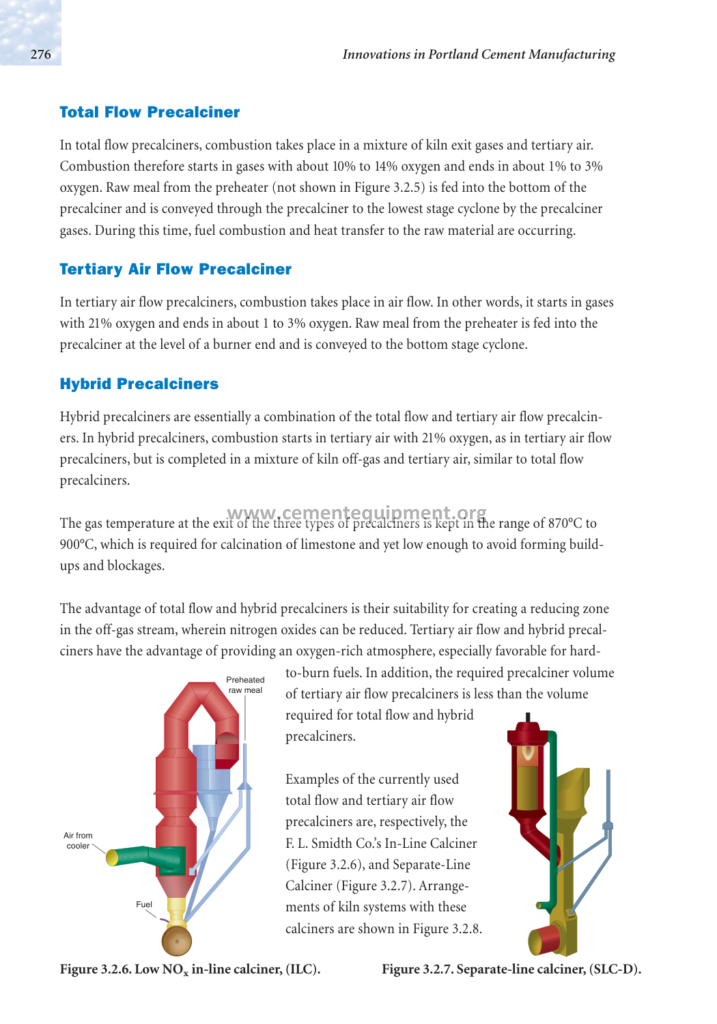
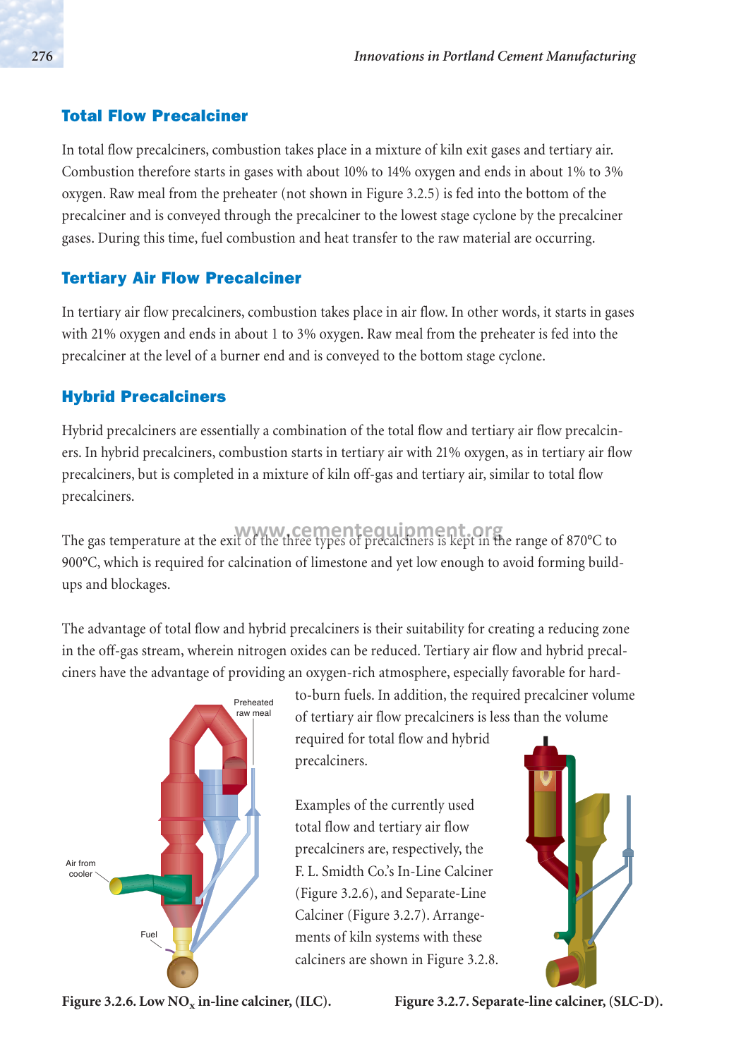
When a calciner has multiple fuel-injection points and the indicated fuel distribution departs from its approved operating target, first verify the actual burner arrangement, fuel type, metering basis and instrument accuracy. Compare synchronized fuel-feed trends with combustion-air conditions, calciner temperature indications, oxygen and CO trends, kiln feed and operating load. An apparent split difference does not by itself prove a blocked nozzle or poor combustion. Do not change fuel distribution, burner settings or control-loop tuning until the process engineer has evaluated combustion stability, interlocks and emissions against the plant’s approved operating envelope. Physical work requires a separately authorized isolation and permit.
Problem / Job
Where multiple fuel-injection points are installed, an indicated difference between measured and intended fuel distribution requires verification; the difference alone does not prove temperature, emissions or clinker-quality effects. The objective is to diagnose the root cause, restore the intended fuel distribution, and confirm stable operation.
Evidence
- Export time-aligned fuel-feed indications for each installed injection point, with units, calibration status, fuel type, feeder state and relevant manual overrides.
- Record kiln feed, fuel quality where available, tertiary-air conditions, draft and comparable operating periods before interpreting the apparent split.
- Review valid calciner temperature, oxygen and CO measurements and their sampling locations; a local reading is not necessarily representative of the whole vessel.
- Compare indicated fuel distribution with independent inventory, feeder or flow checks where the installed equipment permits; document measurement uncertainty.
Decision
Use the installed process diagram and approved operating targets to decide whether the observed distribution is genuinely abnormal. Validate measurements and investigate control and feeder performance before requesting mechanical access. Any corrective change must be approved under the site’s combustion, emissions and management-of-change procedures. Verify results over a documented, plant-approved observation period; no universal number of production cycles establishes successful repair.
7‑Step Diagnostic Workflow
- Establish safe scope. Begin with non-intrusive historian and control-room checks under normal operating authority. Do not enter a hot calciner, open fuel systems or remove burner components during operation. Before any physical access, qualified personnel must plan the shutdown, isolate all applicable fuel, electrical, pneumatic, thermal and stored-energy sources, verify isolation and follow site permits, fire and explosion precautions, and confined-space rules where applicable.
- Confirm the actual distribution target. Review the as-built fuel-injection layout, fuel types, feeder controls and approved operating strategy. Record any manual overrides and compare commanded and measured fuel delivery with design and site operating records. Equal setpoints are not necessarily the design objective; record whether each indicated value is measured or calculated. For fuels reported on a mass-flow basis, calculate each injection point’s thermal input as Qi = ṁi × LHVi, and its thermal fuel split as 100 × Qi / ΣQj. Use compatible units, the same lower-heating-value and moisture basis, and the plant’s approved measurement method. A mass-flow split and a thermal-input split are not interchangeable when fuel heating values differ; for volumetric gas measurements, first apply the approved pressure, temperature, composition and heating-value corrections.
- Validate measurement chains. Check whether each installed fuel stream is measured directly, inferred from feeder speed or estimated from inventory. Compare instrument diagnostics, ranges, timestamps, calibration records and any safe independent checks. Confirm whether injection air is primary, conveying, transport or another design-specific stream; do not assume all calciner firing points have identical air-flow transmitters. Arrange field calibration only under the approved equipment-specific procedure.
- Investigate delivery hardware by fuel type. Compare feeder, rotary valve, screw, pump, gas-train or conveying-system evidence as applicable to the installed fuel. A difference in indicated flow may result from fuel properties, feeder calibration, plugging, leakage or control behavior. Removal or cleaning of injection hardware is not a routine live-process test; only authorized personnel may perform it after the approved shutdown, verified isolation and fire/explosion risk controls.
- Review combustion and conveying air. Identify the actual air circuits and available measurement points on the as-built drawings. Trend fan, damper, pressure, temperature and oxygen data where fitted. A pressure difference may reflect operating load, density, measurement location or restriction; interpret it against design and baseline data. Do not assume fully open dampers are correct or that every injection point has an independently adjustable air manifold.
- Determine corrective action with process engineering. Confirm whether a control override, feeder fault, metering error, fuel-quality change or real distribution issue explains the evidence. Do not retune PID loops or alter fuel and air setpoints merely to force equal readings: the designed split may be intentionally unequal. Any authorized change must follow approved operating procedures, combustion-safety interlocks, emissions constraints and management-of-change requirements.
- Verify and document. After authorized maintenance or process adjustment, confirm restoration of guards, isolation-release records and functional safety checks before controlled restart. Compare fuel-feed measurements, operating load, calciner temperatures, oxygen, CO, draft and relevant emissions with validated baseline data over the site-approved observation period. Record unresolved uncertainty and obtain responsible operations and engineering sign-off.
Diagnostic Matrix
| Evidence | Likely Direction | Next Check |
|---|---|---|
| Indicated fuel delivery differs between injection points or from the approved distribution target | Possible actual distribution change, feeder response, fuel-property variation or measurement bias; the indicated difference does not establish which explanation is correct | Compare commanded and indicated rates on a consistent mass or thermal-input basis as applicable. Check fuel characteristics, feeder status, calibration and measurement uncertainty; use independent verification only where the equipment and approved test procedure permit it. |
| Mass-flow split appears unchanged while the calculated thermal-input split changes after a fuel batch or source change | Possible change in lower heating value, moisture basis, fuel composition or fuel-flow measurement; equal mass delivery does not imply equal heat delivery | Compare representative fuel sampling and laboratory results with the timestamps of the feeder trends. Recalculate each stream’s thermal input on a consistent as-fired LHV basis, account for measurement uncertainty, and seek process-engineering approval before changing fuel setpoints. |
| Persistent temperature differences between installed calciner measurement points at comparable operating conditions | Possible process asymmetry, air/fuel-distribution change, sensor bias or differences in measurement location; temperature alone cannot identify a burner fault | Verify sensor locations and calibration, compare equivalent loads and fuel properties, and trend relevant air, fuel and process variables before planning equipment-specific inspection. |
| CO spike coincident with imbalance | Possible mixing, oxygen availability, fuel-quality, sampling or combustion-control issue; CO alone does not identify the responsible injection point | First validate CO analyzer response and sample conditioning, then compare oxygen, fuel delivery, tertiary-air and other installed combustion-air circuits, draft, fuel quality and operating load. Identify the actual injection-point arrangement before attributing the change to any burner. |
| Control loop oscillation after set‑point change | Possible loop-tuning mismatch, actuator response, measurement delay, interacting control loops or operating-state change; oscillation alone does not prove poor tuning | Check for measurement, actuator or operating-state changes first; only authorized controls personnel may revise tuning under an approved change procedure. |
| Suspected injection-point restriction based on delivery trends; physical blockage confirmed only during an authorized isolated inspection | Possible fuel-delivery restriction; distinguish it from feeder faults, fuel-property changes and metering error before mechanical work | Use safe operating data first. If inspection is justified, arrange a planned shutdown, fuel-system isolation, stored-energy verification and the manufacturer’s approved inspection, repair and restart procedure. Document what was physically found. |
| Measured pressure difference deviates from a validated comparable baseline | Possible flow-distribution change, measurement error or equipment restriction | Confirm pressure-tap locations, instrument health, air density and operating load; inspect only if the evidence justifies an approved shutdown. |
| Manual override active in DCS | Possible effect of an authorized manual control override; actual fuel distribution must be verified separately. | Check why the override was applied and follow the authorized operating procedure before restoring any control mode. |
Acceptance / Verification Criteria
- Validated fuel-feed indications are consistent with the installed system’s approved operating targets and documented measurement uncertainty over a plant-approved observation period.
- Temperature indications at relevant, validated measurement points are consistent with the installed calciner’s approved operating envelope and documented baseline at comparable process conditions.
- Applicable stack-emission measurements remain within the plant’s current permit limits, and validated process CO/O₂ trends satisfy the site’s approved combustion-safety and operating criteria. Verify analyzer availability, sampling location and data quality; OEM guidance informs operation but does not replace enforceable permit limits.
- Validate the applicable installed fuel, air and temperature instruments against documented specifications and their safe test procedures.
- Any changed control strategy or tuning has passed the site’s required engineering review, interlock verification and documented acceptance tests.
Document each verification step in the maintenance log, including the date, personnel, instrument IDs, and measured values. Retain the records for the duration required by the plant’s quality‑assurance program.
Common Mistakes & Repeat‑Failure Traps
- Skipping isolation and permits. Opening fuel lines, cleaning injection hardware or removing guards without an approved shutdown, hazardous-energy isolation and verification can cause fire, explosion, mechanical injury or exposure to hot material. Follow the equipment-specific permit and isolation plan.
- Adjusting set‑points before confirming sensor accuracy. An unverified fuel-flow measurement can mislead the diagnosis and prompt unnecessary process changes.
- Replacing injection hardware without confirming the fault. Not every calciner fuel stream uses a nozzle or common manifold. Verify the installed fuel delivery equipment and fault evidence before authorizing component replacement.
- Ignoring manual overrides. An override may be an authorized temporary safety or operating measure. Identify its purpose and approval status; never remove it without the responsible operator’s authorization and required verification.
- Assuming oscillation proves a tuning fault. Check measurement quality, actuator response and interacting control loops before requesting an approved controls-engineering review.
- Assuming the same air circuit serves every firing point. Calciner fuel injection may use conveying air, dedicated burner air, tertiary air or other design-specific streams. Review the as-built air circuit and validated pressure and flow trends before attributing an indicated fuel-split difference to an air restriction.
- Documenting changes without baseline data. Without a documented comparable baseline, confidence in the effectiveness of corrective actions is reduced; preserve available operating trends and note any limitations in the evidence.
To avoid these traps, follow the workflow in order, verify each measurement, and ensure all actions are logged and signed off according to the plant’s procedural standards.
Related Infinity guides
Build a stronger cement maintenance library
The Infinity for Cement Organization technical package contains 900+ technical files. It is a one-time $249.99 purchase, with instant download immediately after payment and lifetime updates forever at no additional cost.