Quick answer
If differential pressure (DP) across a lubrication-oil cooler drops after cleaning, reduced fouling may explain the change, but reduced flow, an open bypass, incorrect reassembly, internal leakage or faulty pressure measurement can also produce low DP. First verify the measurement and actual oil flow, then compare temperature performance and valve positions at comparable load and viscosity with the OEM data or a documented healthy baseline.
Problem / job
After routine cleaning of a lubrication‑oil cooler, the measured DP falls dramatically. In some cases the oil temperature remains high or cooling performance degrades, contradicting the expectation that a cleaner heat‑exchanger should improve heat transfer.
Evidence
Collect inlet and outlet pressure, oil flow rate (if available), inlet and outlet oil temperatures, the position of any bypass or isolation valves, pump and filter condition, and a detailed record of the disassembly/reassembly steps performed on the cooler.
Decision
Separate a genuine reduction in fouling from low flow, bypass leakage, incorrect re‑assembly, internal leakage, or instrumentation error. The decision path determines whether the unit can be returned to service or requires corrective action.
Eight-step diagnostic workflow
1. Secure the system and verify isolation
Before any physical inspection, lock‑out/tag‑out (LOTO) the lubrication‑oil pump, isolate the cooler inlet and outlet valves, and depressurize the circuit. Verify that the isolation points are clearly labeled and that all energy sources (hydraulic, pneumatic, electrical) are secured according to plant LOTO procedures.
2. Validate pressure instrumentation
Check both pressure taps for blockage, corrosion, or mis‑routing. Confirm that the differential transmitter is correctly wired and calibrated. Where the OEM provides suitable test points, qualified personnel may compare readings using calibrated instrumentation under an approved, pressure-rated test procedure. Do not loosen or connect fittings on a pressurized circuit without the required isolation and depressurization. Any discrepancy indicates a measurement issue that must be resolved before further analysis.
3. Confirm actual oil flow
Low flow will naturally produce a low DP. Measure flow using an approved calibrated instrument where available. If direct flow measurement is unavailable, use only an OEM-approved, validated indirect method; a pump curve and speed alone cannot establish actual oil flow. Review pump condition (bearing wear, impeller damage), filter differential pressure, and oil temperature, because viscosity changes directly affect flow resistance.
4. Inspect bypass and isolation valve positions
Verify that the cooler bypass and isolation valves are in the OEM-designated positions for normal operation; do not assume every bypass is required to be fully closed. An unintended bypass flow path can reduce measured cooler DP while degrading cooling. Confirm positions using the approved indicators or an authorized isolated inspection method, and document the verified settings before the controlled return-to-service test.
5. Review cooler re‑assembly
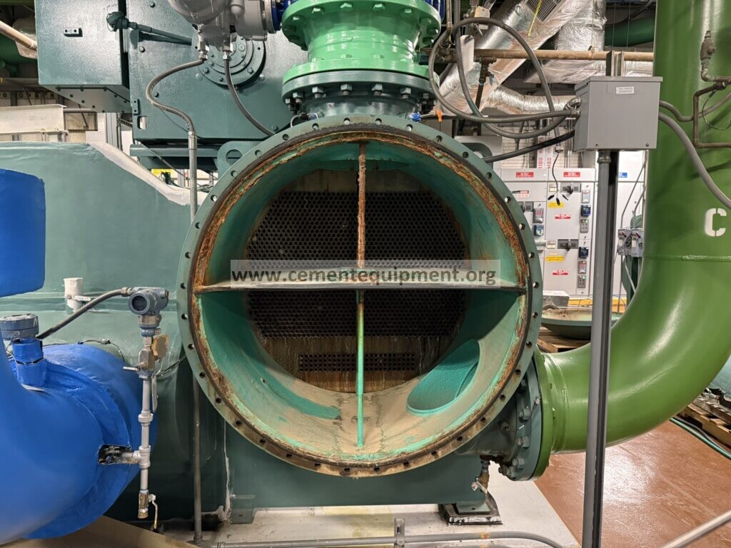
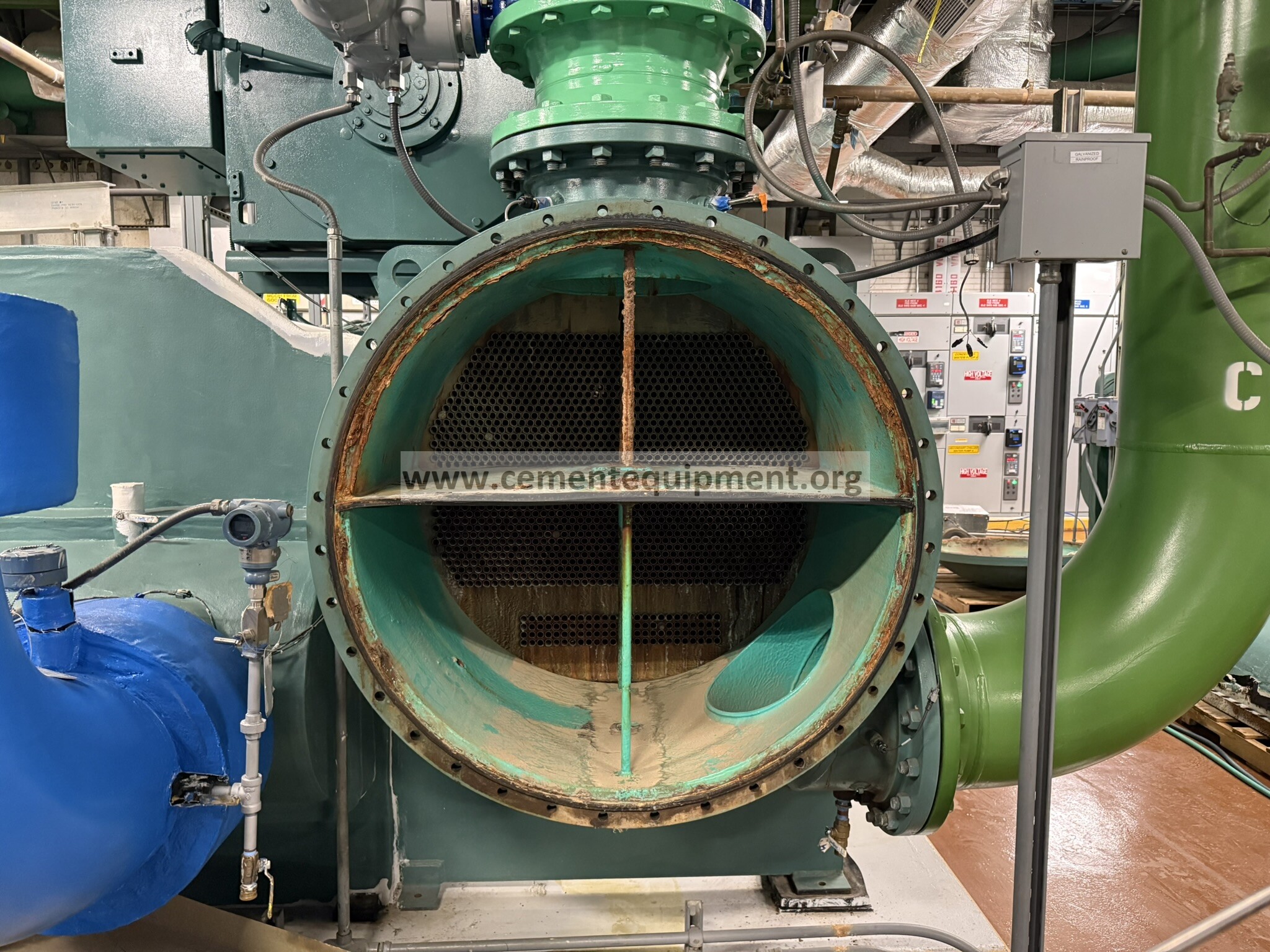
For plate‑type or shell‑and‑tube coolers, ensure that all plates, gaskets, baffles, and tube bundles are installed exactly as the OEM drawing specifies. Missing plates, reversed orientation, or misplaced baffles can create unintended flow shortcuts. If the cooler was disassembled, compare the re‑assembly checklist with the work order and photograph key assembly points.
6. Detect internal leakage or seal damage
Inspect the cooler housing for signs of oil leakage, especially at flange joints and tube‑sheet seals. A damaged seal can allow oil to bypass the heat‑exchange surface, lowering DP and degrading cooling. Use only the cooler manufacturer’s approved leak-test and inspection procedure, with compatible test media and specified test pressures. Do not introduce unapproved fluids or tracers into the lubrication circuit.
7. Correlate thermal performance with DP
Record oil-side and cooling-medium inlet/outlet temperatures, oil flow, and operating load at a stable condition. Compare the readings with the OEM performance data or a site baseline taken at comparable flow, viscosity, inlet temperatures and load. A lower pressure drop or larger oil temperature change alone does not prove that cleaning succeeded: verify cooling duty, adequate oil flow and acceptable bearing or gearbox supply conditions together. Investigate bypass leakage, assembly defects or measurement error when the combined evidence disagrees.
8. Re‑establish normal operation
Following the approved pre-start inspection, authorized personnel may release isolation under the site procedure and conduct a controlled startup with safeguards intact. Capture final DP, flow, and temperature data for the acceptance record.
Evidence‑to‑decision matrix
| Evidence observed | Likely underlying direction | Next diagnostic check |
|---|---|---|
| Low DP & low measured flow | System‑wide flow restriction (pump, filter, valve) | Inspect pump performance, filter DP, valve positions |
| Low DP & outlet temperature higher than baseline | Bypass path or internal leakage | Check bypass valve closure, re‑assembly integrity, seal condition |
| Low DP & outlet temperature lower than baseline | Reduced fouling is possible, but a lower outlet temperature alone does not confirm cleaning effectiveness; operating load, inlet temperature and oil flow may also differ. | Confirm actual oil flow and comparable operating conditions; document successful cleaning only when OEM or site performance and supply criteria are met. |
| DP reading deviates after instrument maintenance | Measurement error | Calibrate pressure taps, verify transmitter wiring |
| Problem appears immediately after cooler re‑assembly | Incorrect component placement or missing hardware | Cross‑check assembly checklist, inspect plates/baffles |
Return‑to‑service acceptance criteria
- Actual oil flow is verified using a suitable measurement method or an OEM-approved, validated indirect method; a pump curve alone does not prove actual flow.
- Measured DP is consistent with the verified flow (reference the OEM’s DP‑vs‑flow curve or a site‑specific baseline).
- All bypass and isolation valves are in their designated positions, with visual confirmation and documented valve stem readings.
- No external leakage is detected during the site-approved monitored test period, and any internal leakage checks pass the manufacturer’s approved test method.
- Oil supply temperature and cooling performance remain within OEM or approved site limits at comparable load, oil flow and cooling-medium conditions; differences from the pre-cleaning baseline are investigated rather than automatically rejected.
- All pressure‑instrumentation calibrations are within the acceptable tolerance defined by the plant’s instrumentation policy.
- Before returning the cooler to service, the designated authorized personnel complete the site-required inspection, confirm guards and protections are restored, remove isolation only under the approved lockout/tagout release procedure, and document the required operations and maintenance sign-offs.
Common mistakes and repeat‑failure traps
- Celebrating low DP without checking flow. A reduced pressure drop can mask a serious flow restriction or bypass; always verify flow and temperature.
- Adjusting pump discharge pressure to “restore” DP. Raising pump head to force a higher DP can overload bearings and increase oil temperature, leading to premature wear.
- Ignoring bypass‑valve position. A valve left partially open after cleaning creates a hidden shortcut that defeats the cooler’s heat‑transfer function.
- Assuming pressure transmitters survived maintenance unchanged. Transmitter cables or pressure‑tap seals can be disturbed during disassembly; a post‑maintenance calibration check is mandatory.
- Re‑installing plates or baffles in the wrong sequence. This creates unintended flow channels and may cause uneven fouling or vibration.
- Skipping LOTO procedures. Working on a pressurized oil circuit without proper isolation can cause sudden oil release, injury, or damage to instrumentation.
- Failing to document the exact re‑assembly configuration. Without a clear record, future maintenance may repeat the same error, leading to recurring low‑DP events.
Related Infinity guides
Build a stronger cement maintenance library
The Infinity for Cement Organization technical package contains 900+ technical files. It is a one-time $249.99 purchase, with instant download immediately after payment and lifetime updates forever at no additional cost.