Contents
3 GOLDEN RULES FOR CLINKER COOLER
TARGETS of the Clinker Cooler
1) Heat recuperation from hot clinker
to minimize the required fuel input (combustion) for the kiln system
2) Cooling of clinker
Target 100 – 150 °C clinker outlet temperature
for easy clinker conveying, clinker storage and cement grinding
Grate Cooler Process Terminology

Grate Cooler Equipment Terminology

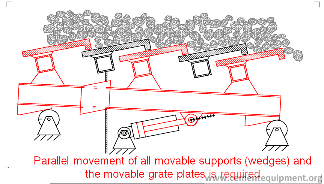
Grate Assembly

Principle of Grate Movement
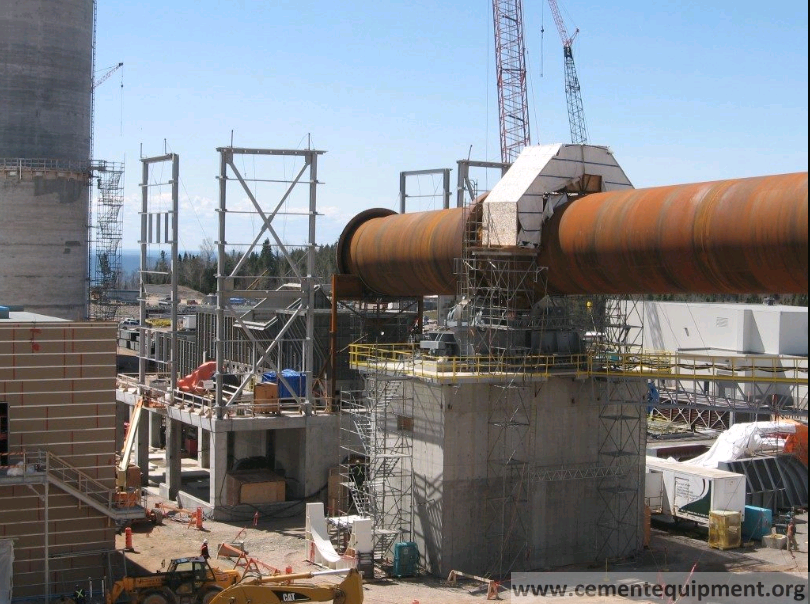
The Clinker Cooler House
Typical Weaknesses of Older Coolers
- No static cooler inlet section
- Outdated grate plate technology (e.g. Folax or Volga plates)
- Misalignment of grate
- Internal drag chain
- Beam aeration
- Large compartments
- High grate area load [t/d/m2]
- Low grate width load [t/d/m]
- Low specific cooling air [Nm3/kgcli]
- Grate geometry (steps, inclination)
- No reliable process indicators
- Manual control without interlocks
- Mechanical grate drive
- Hammer crusher
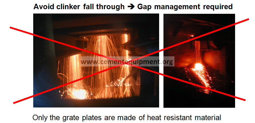
1st rule: Keep the clinker on the grates = minimize clinker fall through>improve gap management
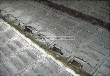
Cooler grate plates are designed to carry the hot clinker bed and are made of heat-resistant steel.
The rest of the cooler is not designed for such high temperatures; particularly the supporting structure beneath the grate must not be exposed to more than 200°C.
Hot clinker must be prevented from spilling through the grate by keeping all functional gaps tight (gap management).
2nd rule:
Controlled air distribution into the clinker
>minimize air losses
> compartment sealing required !!!
Cooling air must follow the intended channels and cool the intended areas.
This cannot be achieved if the cooler leaks air through worn plates, gaps, poor compartment seals, or leaking hopper discharge valves.
Also, intake of false air through the kiln outlet seal, clinker crusher, or cooler exhaust-air system must be minimized.
Unsealed compartments
3rd rule:
Operate with high clinker bed
> low grate speed
> increased heat recuperation
A high clinker bed increases the residence time of the air in the clinker, essential for good heat exchange.
The cooler should always be operated at the lowest possible grate speed.
Cooling Time – Retention Time

Keeping the Clinker on the Grate is the Key
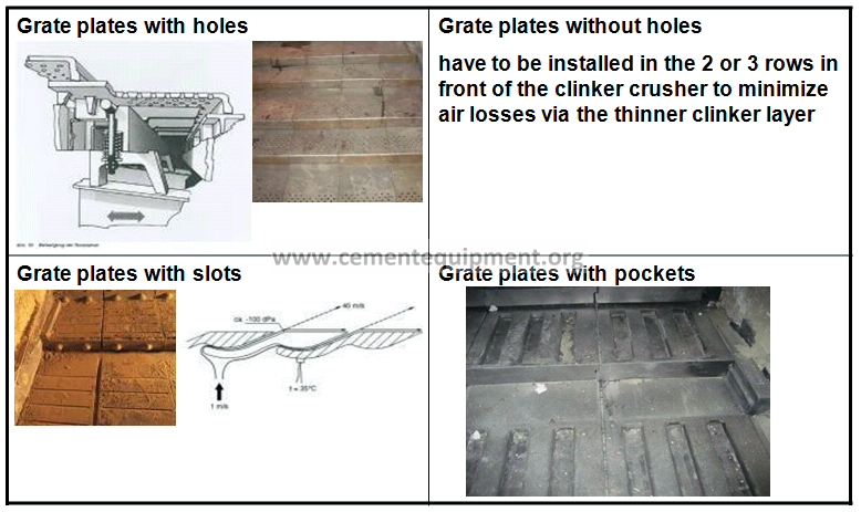
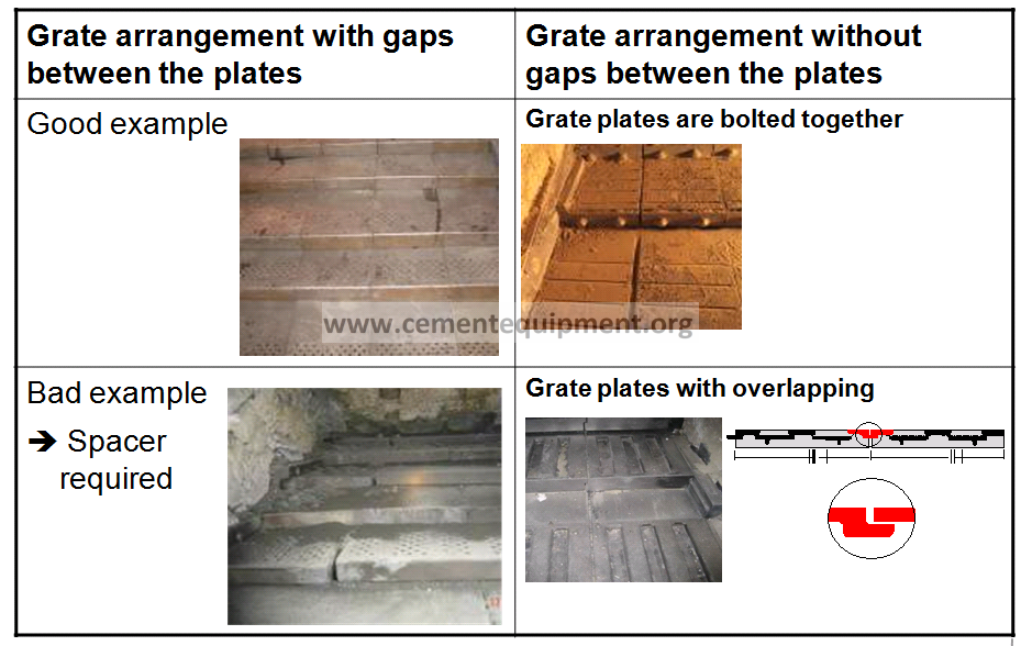
Gap Management

Overview Grate Plates: Air openings
Grate Plates: Gap between the plates
Template to check Dimensions on Grate Plates
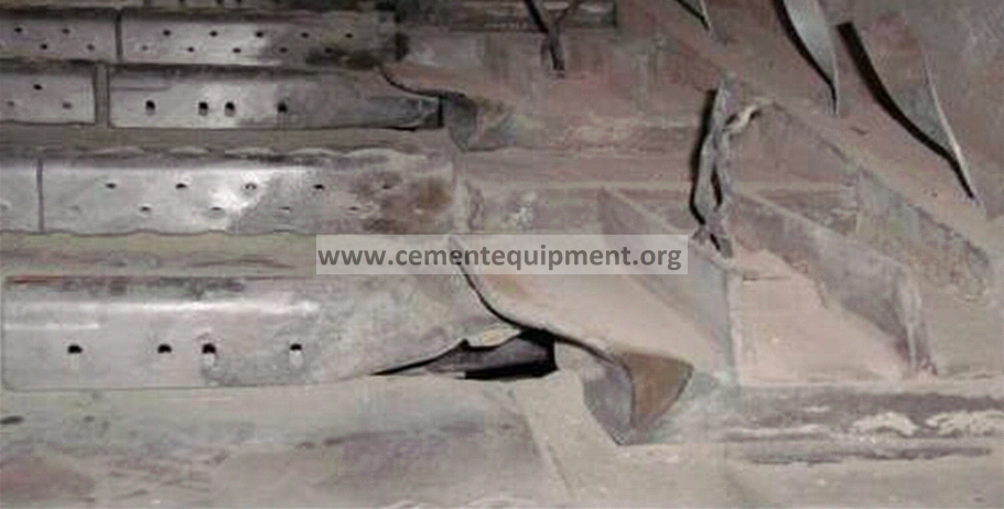
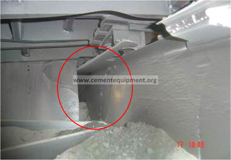
Red river formation / excessive wear on side
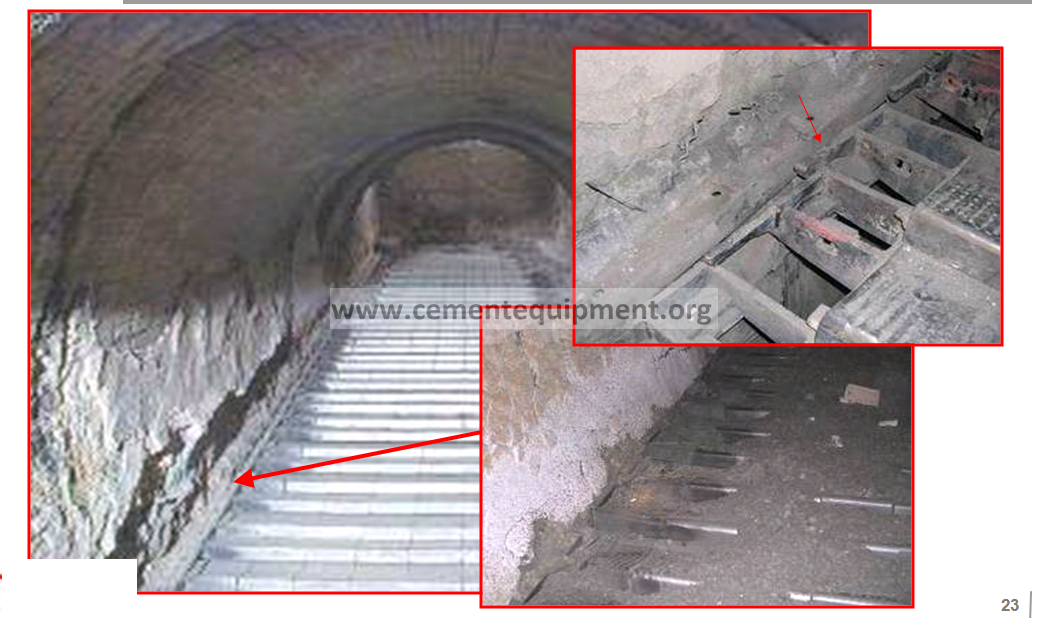
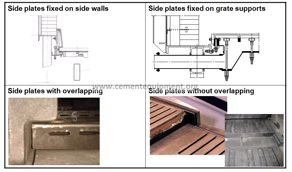
Overview Side Plate Design
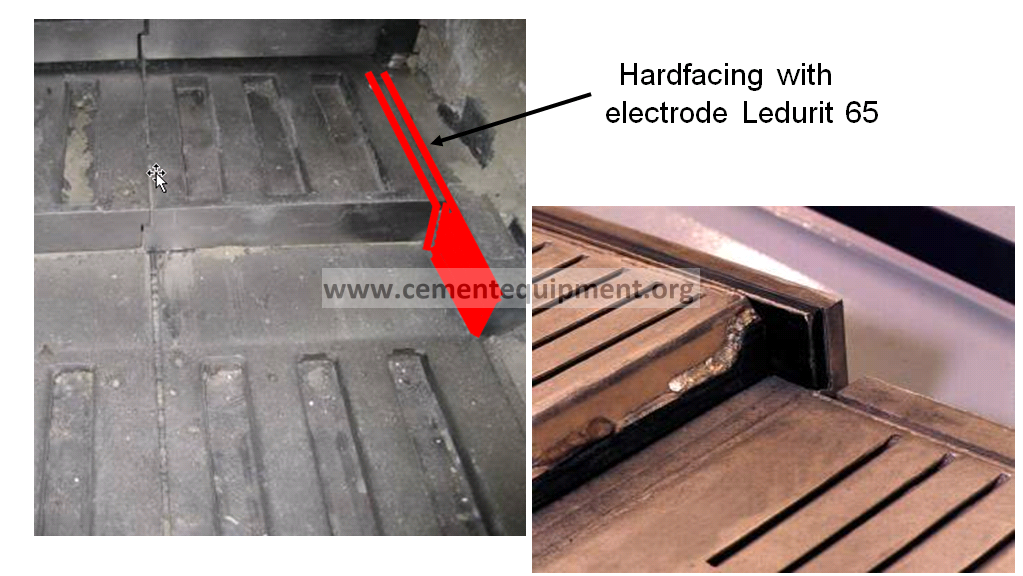
Hardfacing to Maintain the Side Gap
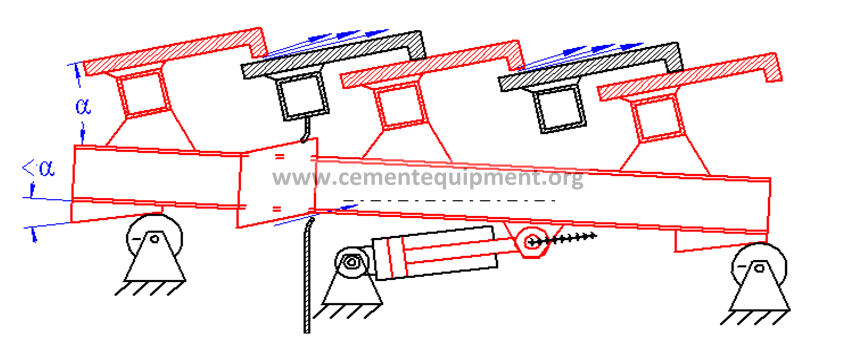
Misaligned Grate Movement
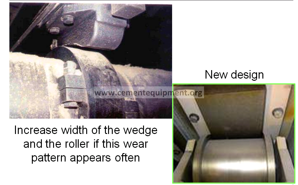
Wear on Support Rollers and Wedges
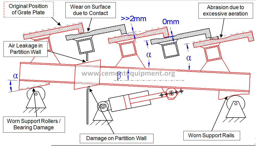
Wear on the Wedges
Targets for gaps on the grate arrangement
1.Gap between the grate plates: max. 2 mm
2.Gap between fixed and movable row: 1 mm
3.Gap between movable and fixed row: 3 mm
4.Side gap:
-5 to 7 mm if side plates are fixed on side walls
-2 mm on movable rows if side plates are fixed on the fixed grate plate supports (0 mm in the area of the fixed grate plates supports)
5.Grate guidance: 0.25 mm on each side of the guide roller
(Max 1 mm in total)
Measure:
If required minimize gaps with spacers or weld-on front pieces
Rules for the grate re-alignment
1.Replace deformed and worn out equipment.
-Steel frames deformed > 5 mm
-Support rollers and wedges worn out > 3 mm
-Grate plates with a remaining thickness < 8 mm
-Washed out side plates
2.Establish quality standards and quality control for key parts (grate plates, grate plate supports, side plates, support rollers and wedges)
3.Use centre position (centre of stroke length) of the grate as reference for the grate alignment
4.Minimize shimming.
If shimming is required fix the shims by welding
5.Avoid shearing forces for screw connections
6.Assure plate fixation by tack welding
7.If required minimize gaps with spacers or weld-on front pieces
Final Messages Gap Management
> Detect and eliminate design weaknesses
> Establish quality standards for grate equipment
> Preventive maintenance is essential
> A general grate alignment is required every 3 to 5 years minimum
Target: No unexpected stops due to cooler failures
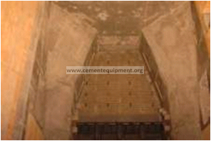
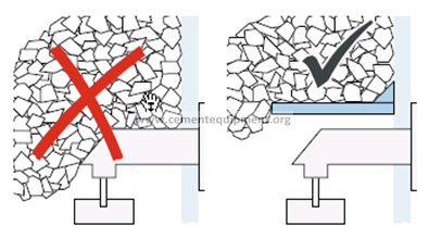
Static Cooler Inlet Section: Requirements
- Rapid clinker cooling to avoid clinker agglomeration
(clinker liquid phase) - Clinker distribution from the drop point to the entire grate width (horse shoe)
- Reduced thermal load of the grate equipment (operational safety)
- 100% sealed (no air losses)

Criteria for Static inlet
- Adequate number of air cannons required.(vessel size min. 100 liter; nozzles required)
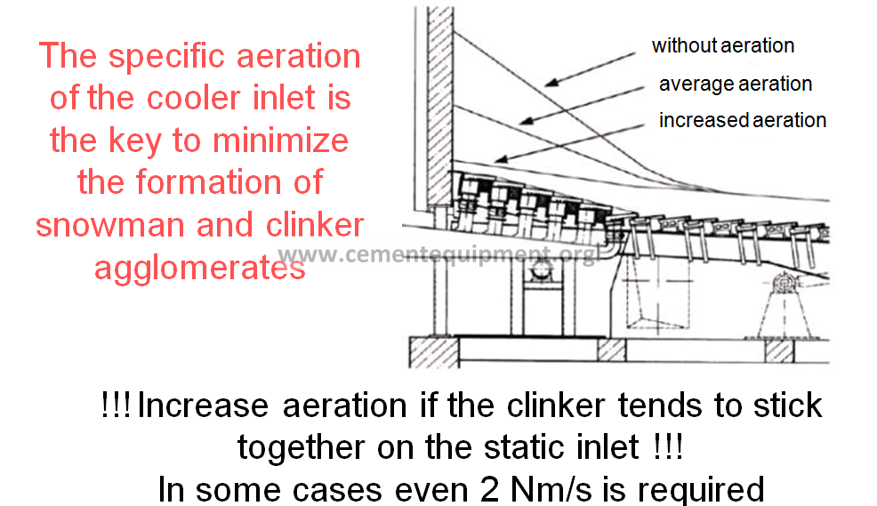
- Installed specific aeration min. 1.8 m3/m2/s.
- Static pressure of the fans min. of 100 mbar under grate pressure.
- Downwards slopped grate plate (5° to 8°) to create downhill force for big lumps
- Static (dead) clinker layer on the grate plates before start-up
- Burn tip position: 500 to 1000 inside cold kiln
- Clinker drop height: > 4 meter
- Sufficient air required already during start-up
Layout Details
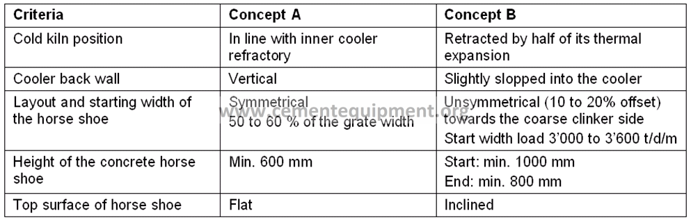
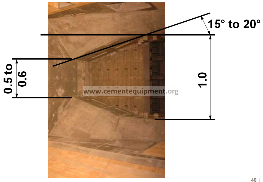
Horse Shoe Layout (Concept A with inclined walls)
Horse Shoe Design and Air Blaster Location
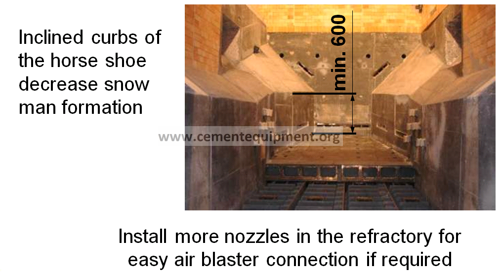
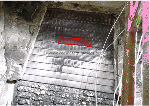
Measures to Minimize Snow Man Formation
1.Design of static cooler inlet (horse shoe)
2.Air Blaster location
3.Air blaster operation (sequence)
4.Specific aeration of the cooler inlet
5.Manual measures to get rid of snow man
Specific Aeration of the Static Cooler Inlet
Manual Measures to Destroy a Snowman
High/low operation:
1.Pile up clinker behind the snow man by decreasing grate speed and flow on the static inlet
2.Shoot the air cannons manually
3.Increase grate speed and flow that the snow man can flow down the static inlet
4.Repeat this procedure (high/low operation) after 15 minutes if required
5.In hard cases the use of poles, lances or cardox might be required
Sufficient air required already during start-up
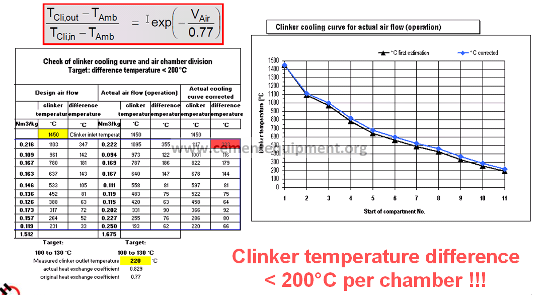
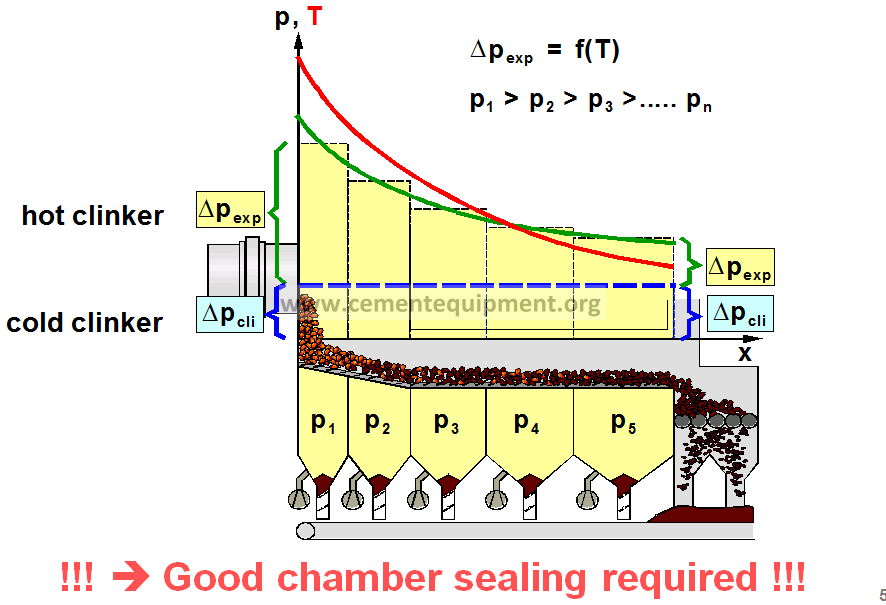
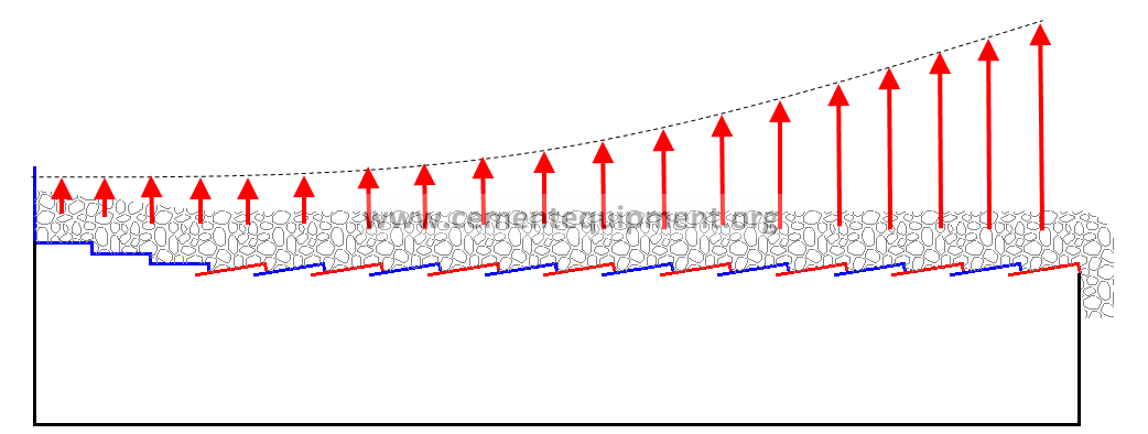
Air Distribution: Clinker Temperature Profiles
Hot clinker at the cooler inlet and at the border sides
= high pressure resistance.
Cold clinker at the cooler outlet and in the centre of the grate
= low pressure resistance.
The cooling air escapes in aeras of low pressure resistance.
> Small aeration field in the recuperation zone and a good chamber sealing is required !!!
Target:Minimize cooling air losses to cold clinker areas
Air Distribution Template

Aeration Scheme / Air distribution

Clinker Cooling Curve and Air Distribution
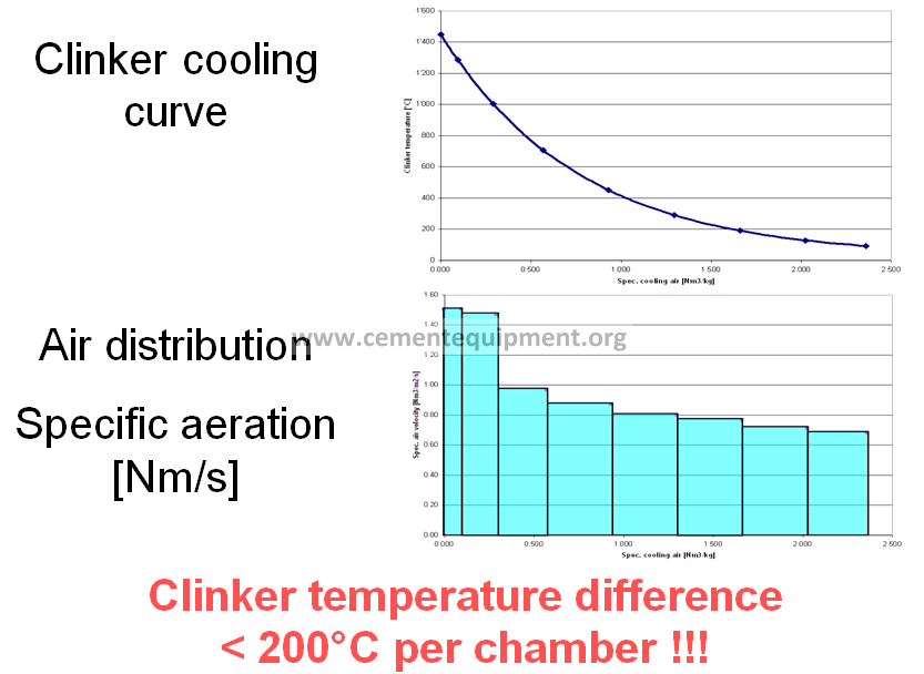
Clinker Cooling Curve Calculation
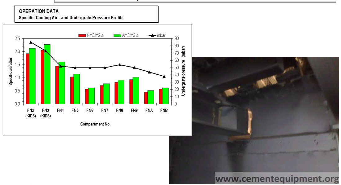
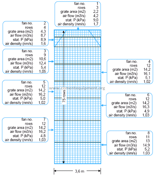
Cooling air fans
- Undergrate pressure
- Fan curve
- Fan calibration
- Fan assessment
Pressure Drop of the Aeration System

Clinker Pressure Drop = f (Clinker Temperature)
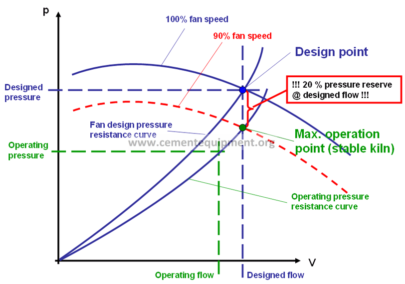
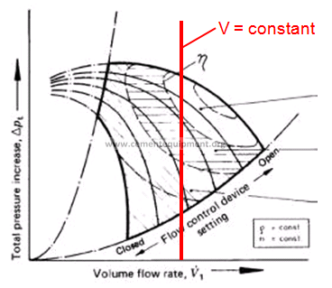
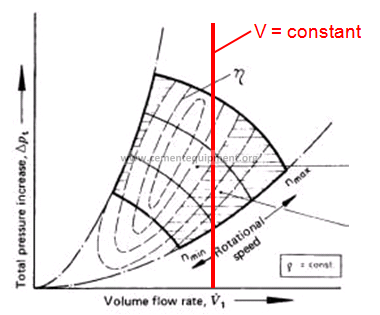
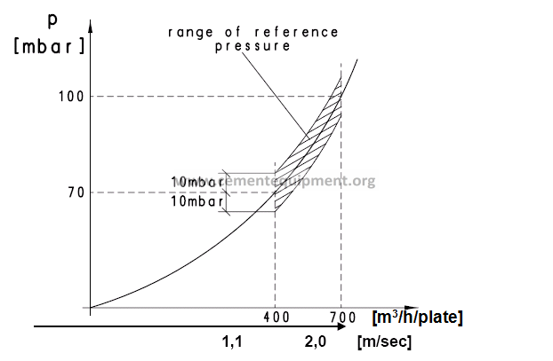
Fan Curve, Pressure Resistance Curve
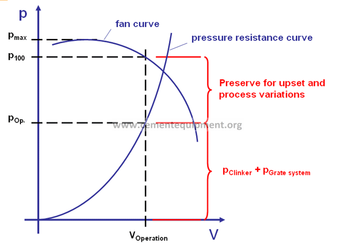
Recommended Fan Speed
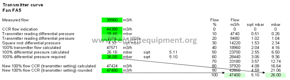
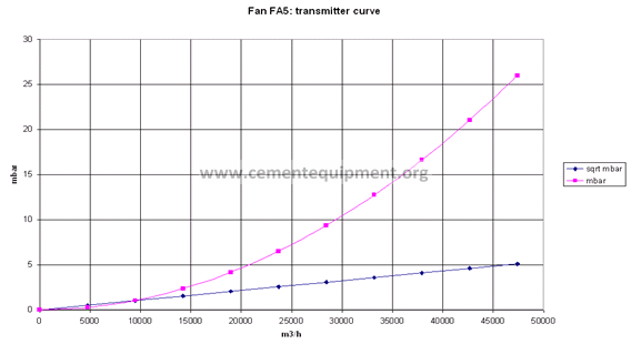
Fan Calibration
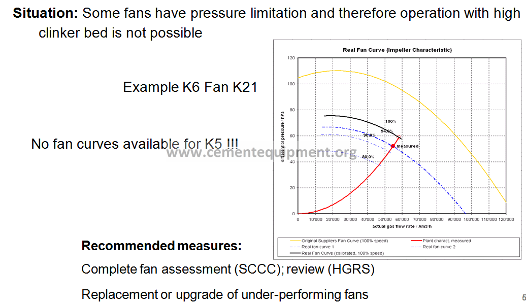
Situation: CCR flow indications are not reliable

Recommended measures:
Fan calibration by automation and process team
Fans: Air Flow Calibration
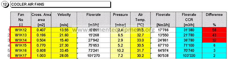
Fan Assessment:Example
Compartment Sealing
What is the Partition Wall?
A barrier between the different chambers, to avoid air escape from a chamber with higher pressure to the next chamber with lower pressure
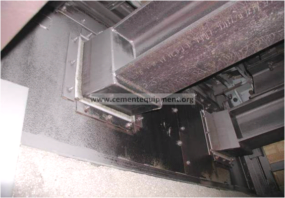
Leakage in Partition Wall

Air Losses via Partition Walls
- Without barriers the air escapes to the cooler end (less pressure resistance of colder clinker)
Correct Air Distribution
- The air pressure is adjusted to achieve the following air distribution
- The partition walls are tight
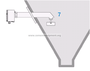
Installation of hopper sensors
Targets
- Improve hopper sealing by remaining clinker layer inside the hopper (minimize air losses)
False Air Minimization
> At cooler exhaust air system
> Kiln nose ring cooling
> Kiln inlet and out seal
> Doors, inspection windows
Target: Reduce cold air intake
Final Messages Controlled Air Distribution
> Improve air distribution and clinker cooling curve
> Fan performance and control is important
> Compartment sealing is essential
Target: Minimize cooling air losses
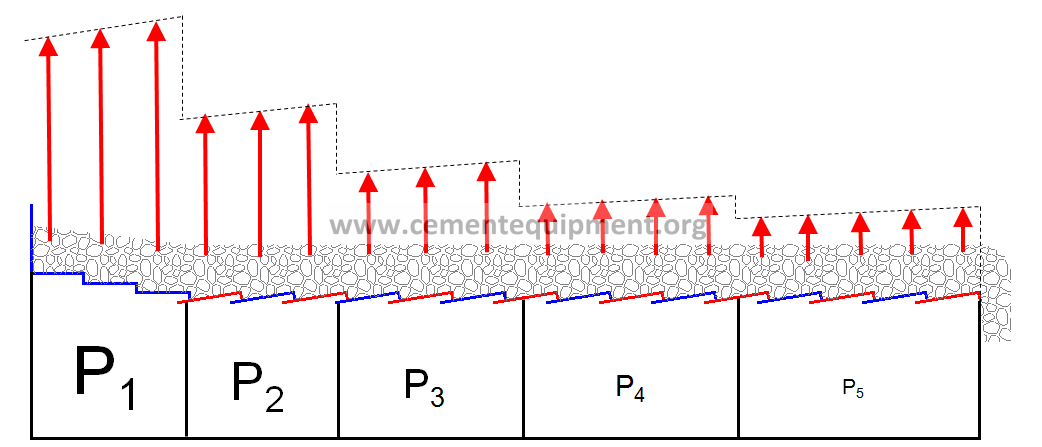
Clinker Bed Height
Increased clinker bed height
> increased retention time of air and clinker
> increased cooling time
> improved heat transfer
> improved clinker cooling
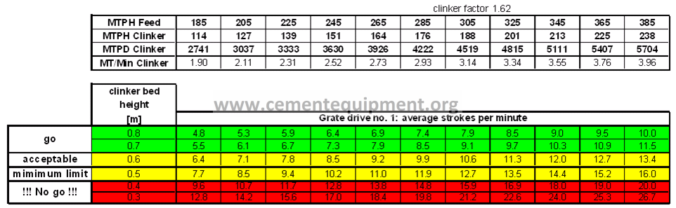
Strokes per Minute
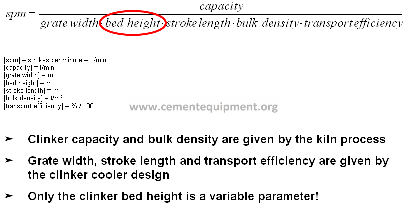
Clinker Bed Height
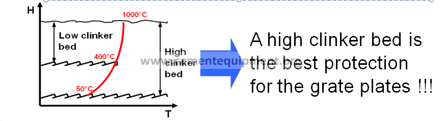
Low clinker bed (< 500 mm)
>Limited air retention time in clinker
>Short clinker retention time in cooler
>Short cooling time
>Low heat transfer
>Risk of grate plate overheating
>High clinker exit temperature
>Low secondary air temperature
>Limited heat recuperation
>Poor cooler efficiency
>Frequent equipment overheating
High clinker bed (> 600 mm)
>Higher air retention time in clinker
>Long clinker retention time in cooler
>Increased cooling time
>Improved heat transfer
>Best protection for grate plates
>Lower clinker exit temperature
>Higher secondary air temperature
>Increased heat recuperation
>Good cooler efficiency
>Increased cooler availability
Grate Cooler Control Loops
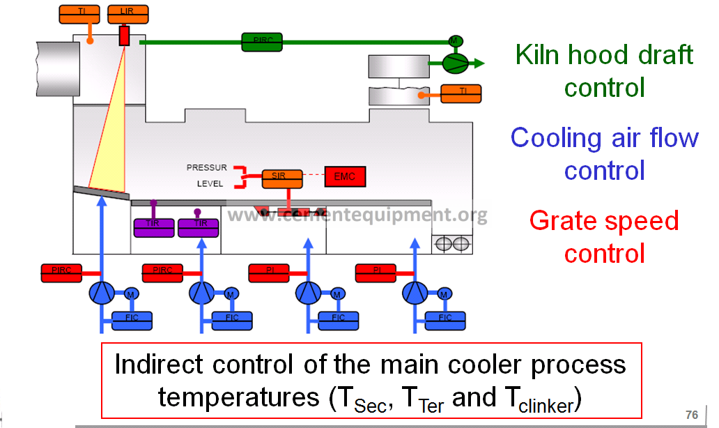
Why Cooling Air (Fan) Control?
>Without control the cooling air flow varies due to pressure drop changes in the clinker bed

>Avoid air losses
> Improve air distribution
Basic Principle of Cooling Air Flow (Fan) Control
Setpoint target: see fan operation table
Actual air flow > setpoint
> fan damper closes or fan speed reduces
Actual air flow < setpoint
>fan damper opens or fan speed increases
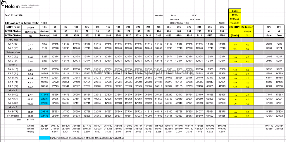
Air Flow Table
Why Grate Speed Control?
>Minimize fluctuations of recuperation temperature
>Avoid overfilling of the grate
(downtime for manual emptying of the grate)
> Avoid emptying of the grate
(overheating of the grate plates)
>Grate speed control prevents the clinker bed
resistance from exceeding the pressure capabilities of the cooling air fans
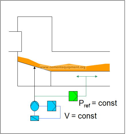
Grate Speed Control (UG Pressure Control)
Basic control principle:
Actual UG pressure > setpoint
> grate speed increase
Actual UG pressure < setpoint
>grate speed decrease
Precondition:
Constant flow of the reference fan
Setpoint of Grate Speed Control
Setpoint = f (reference air flow)
Disturbance of Grate Speed Control
If reference flow is not constant:
> e.g. 3% flow fluctuation
> up to 9% pressure dead band

Grate speed may tend to over and under driving
Grate Speed Control (Level Control)
LevelRadar for direct measuring of the clinker bed height
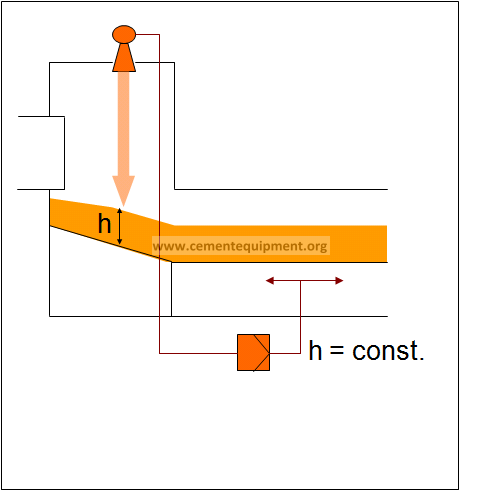
Guideline for grate speed
Operation Interlocks
| Malfunction | Action |
| Grate drive tripped | Kiln release taken off after 5 minutes |
| Fan tripped in cooler inlet | Grate drive stops after 5 minutes |
| Fan tripped in remaining recuperation zone | Grate drive stops after 5 to 10 minutes |
| Fan tripped in cooling zone | Grate drive stops after 15 to 20 minutes |
| Clinker crusher tripped | Grate drive stops immediately (after 5 minutes) |
| Clinker transport tripped | Grate drive stops immediately (after 5 minutes) |
| Cooler exhaust air fan or kiln ID fan tripped | Grate drive stops immediately Cooling air flow reduced to 50% |
| Cooler exhaust air fan and kiln ID fan tripped | Grate drive stops immediately All cooling air fans off immediately |
Main Issues Grate Cooler Control
1.Grate drives and grate speed control have a key function for heat recuperation and clinker cooling
2.Reliable process indication
>Reliable process control + interlocks
> Increased equipment availability
3.If it is not measured it will not be improved
Summary Clinker Cooler
1.Golden rules for clinker cooler are key
2.Gap management
3.Air distribution + fan performance„Air Flow Table“
4.Compartment sealing is essential
5.Clinker bed height = cooling time„Grate Speed Guidelines“
6.Automatic cooler control + interlocks