Contents
5. Work Instructions of Containers
5.1 Scope and Objective
This chapter explains the procedures of testing and inspecting containers. The chapter starts by listing the tools and equipments required to test containers and then moves to the procedures that are to be followed throughout the test. The chapter concludes by documenting the process of creating certificates and rejection reports for containers.
5.2 Required Tools for Testing Containers
- measuring tape,
- OD/ID caliper,
- Magnetic AC yoke,
- Load cell,
- Penetration dye check spray (there any of the container’s components are made of an aluminum alloy)
5.3 Containers Testing Instructions
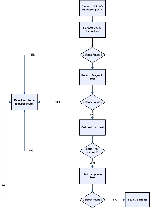
5.3.1 Containers’ Testing Process Overview
The overall process of testing and inspecting hooks is graphically illustrated in the flowchart shown on page 22.
5.3.2 Test Preparations
- Take container’s information, measurements and record them into the form xxxxx
- Clean xxxxxxxxxx HOW?
- Prepare the lifting point that will be used to apply tension to the container during the proof load test. xxxxxxx
- Make sure that the battery of the load cell’s remote reader is in good condition by turning on the remote and making sure the “battery low” indicator is not ON.
- Check the calibration date of load cell and make sure that its last calibration is still valid.
- Determine the proof load weight of the hook using the British Standard xxxxxxxxxxxx.
- Test the AC yoke before commencing the job as follows:
- connect the AC yoke to the power mains
- place the test piece on the floor or on a wooden table
- place the yoke on top of the test piece
- Switch the AC yoke on by flipping on the ON/OFF switch of the yoke to apply magnetic field to the test piece.
Try lifting the test piece with the yoke to ensure that it applies sufficient magnetic field.
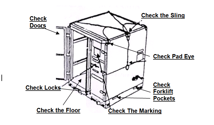
5.3.3 Visual Testing of Containers
- The examination must be carried out in adequate light, free from shadow.
- Check to make sure that the safe working load and identification marks are legible and corresponds with the test certification in accordance with BS 7072.
- Visually examine all eye pads both from inside and outside to ensure they are free from defect. A non-destructive test (MPI.) shall be carried out at the discretion of the test engineer.
- Visually examine floor inside and underneath. A hammer may be used to loosen and remove any flaking rust to check condition of floor.
- Check condition of floor bears to make sure they are free from corrosion.
- Examine the floor and make sure that it is substantially flat with no sign of distress or overload.
- Check base weld, both inside and under side for defect.
- Check for abnormal dents, or tears.
- Check condition of fork lift pockets particularly the bottom strap at point of entry.
- Check fork lift pockets to ensure that they have a minimum opening of 200mm x 90mm
- Check fork lift pockets to ensure that are located no more than 2.05m apart; measured from the centre of pocket to centre of the other pocket.
- Check release catches and open the doors fully (if fitted) checking the freedom of operation and alignment.
- Check condition of door seals (if fitted).
- The diameter of holes in pad eyes shall match the shackle used, tolerance between shackle bolt and pad eye hole diameter shall not exceed 6% of the nominal shackle bolt diameter.
- Check to ensure that any difference in the diagonal measurements between pad eyes’ centers does not exceed 0.2% of the length of the diagonal or 5 mm whichever is greater.
- The pad eye must be cleaned and free from delirious matter.
- Ensure pad eye is smooth and free nicks , gouges and any other defects that could act as stress raisers.
- Check pad eye for wear, distortion, elongation and signs of cracking.
- Check all welds and heat affected zones for signs of damage ,distortion ,and overloading.
- Check all stenciling and paint marking and make sure they are done according to BS 7072.
If any faults are found at the time of examination which would affect the use of machine, then it must be with drawn from services and details recorded on test report
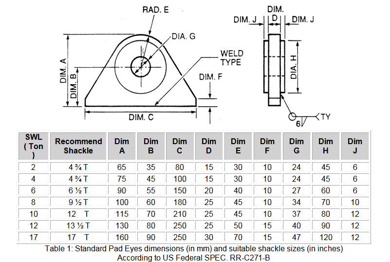
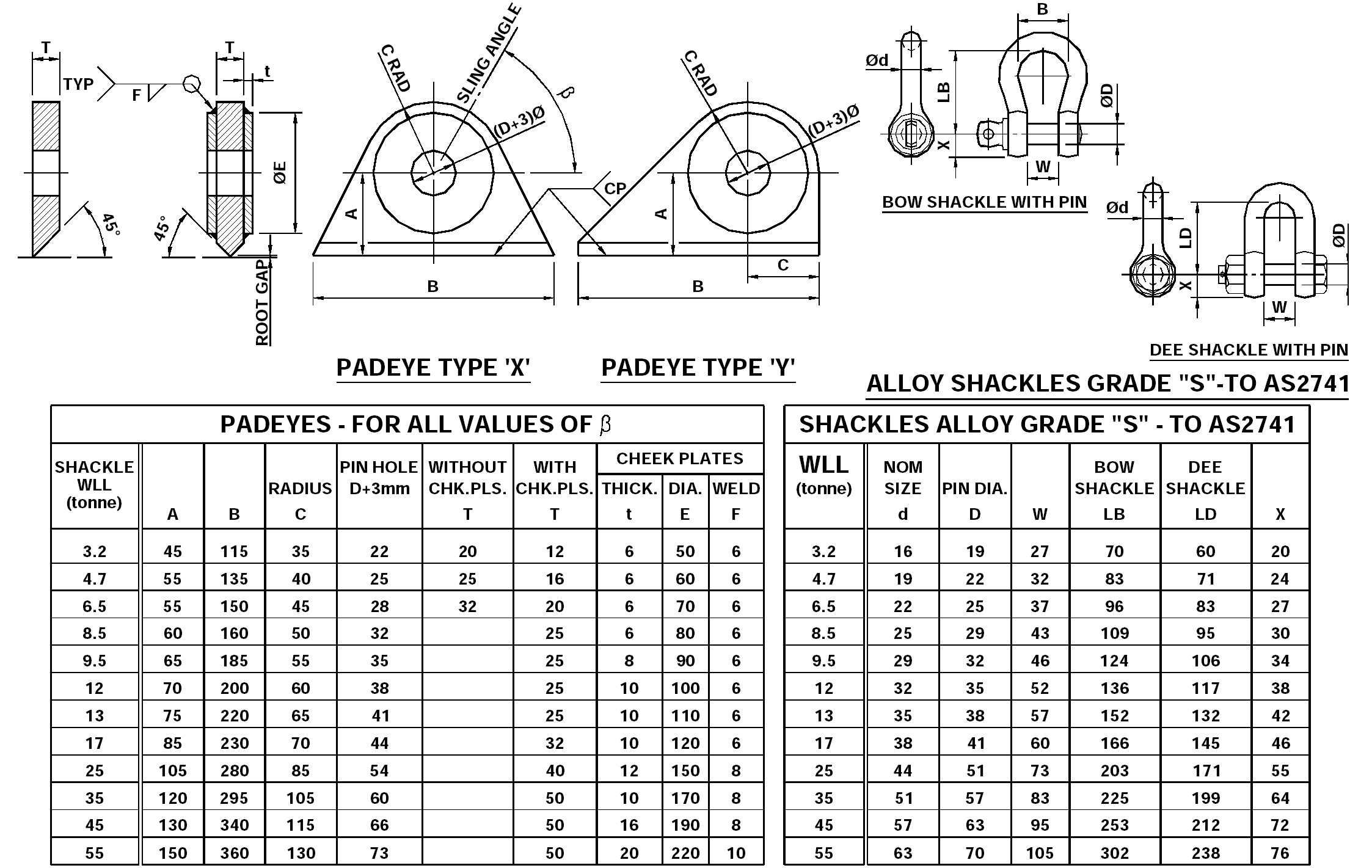
Table 2: Shackles standard dimensions according To US Federal Specifications
All rejection criteria are in accordance with both manufacturer’s recommendation and the relevant standards.
5.3.4 MPI (Magnetic Particle Inspection) of Containers
According to BSI-6072, ASNT Training Program for MPI, ASNT Training Program of Dye Penetrant)
Structure Welds: All accessible load bearing welds should be MPI examined by
- Adjust the spacing between the yoke’s probes so that both probes establish physical contact with welds.
- Switch the AC yoke ON
- Apply the dry powder to the welds (while the AC yoke is still on) so that the whole is covered with powder
- Blow the powder off the welds. Use a blower when available
- Visually inspect the traces of the powder on the hook for any indications of cracks
- If any cracks exist, reject the containers and issue a rejection report
- If not crack exist, continue the test as follows
- Repeat previous steps for the all welds to ensure freedom from defects.
Lifting points: The lifting points should be MPI examined for distortion, mechanical damage or any other sign of distress or overload to ensure freedom from defects.
Lifting set: If the container is fitted with lifting set this should be MPI examined to ensure freedom from defects by using previous steps for the all welds to ensure freedom from defects
Pad eye should be MPI examined by using previous steps for the all welds to ensure freedom from defectsfor wear, distortion, elongation and signs of cracking
NOTE: it is recommended to use the magnetic wet method when testing rough surfaces. Instructions for performing wet magnetic testing are as follows:
- Clean the welds or surfaces that are to be tested by a suitable cleaning method.
- Shake cans of contrast spry can and black ink very well prior to use.
- Apply a thin layer of the contrast and distribute it well over the area to be tested.
- Wait for the contrast to dry off.
- Apply magnetic field to the area to be tested using a magnetic yoke.
- Apply the black ink spray over the area to be tested.
- Indications for defects, if exist, will appear immediately.
Check all welds and heat affected zones for signs of damage, distortion, and overloading.
5.3.5 Proof Load Test of Containers
- Place a uniform distribution test load over the floor of the container in such a way that combined weight of the container and test load is equal to two times the maximum gross weight
- Proof load testing from all point lifting: the container shall be loaded to a total gross mass of 2.5 R and lifted using all pad eyes according to BS EN 12079. (R is the container’s rating i.e. the maximum gross mass of the container and its cargo in kg.)
- Proof load testing from two point lifting: An offshore container fitted with four pad eyes shall also be fitted from only two pad eyes situated diagonally opposite each other with a total mass of 1.5 R according to BS EN 12079.
Lift the container with a lifting set suitable for test purpose, i.e. one which as an included angle of approximately 90 between the relevant sling legs. If a container is normally fitted with a lifting set this set should not be used for the proof load test.
4-Maintain the proof load on the container for a minimum 5 min.
5-No deflections during testing shall be greater than 1/300 of the span of the member.
6-The container shall show no permanent deformation.
for any inquiries or services please contact cementforums@gmail.comBest Regards ,,