Contents
WORKING PRINCIPLES OF COOLER
[wpecpp name=”package + Updates forever” price=”250″ align=”center”]
WHY DO WE NEED A CLINKER COOLER..??
1.To recuperate heat from clinker.
2.Hot clinker – difficult to convey
3.Hot clinker shows negative effect on grinding process
4.Proper Cooling improves the quality of Cement
WHY DO WE NEED A CLINKER BREAKER AT THE COOLER DISCHARGE..??
To crush the clinker to the acceptable feed size for cement mill (Ball Mill / VRM).
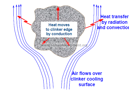
MODES OF HEAT TRANSFER INVOLVED IN CLINKER COOLING
-Conduction
-Convection
-Radiation
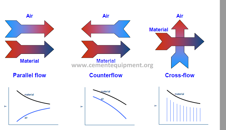
TYPES OF FLOW
TYPES OF COOLER
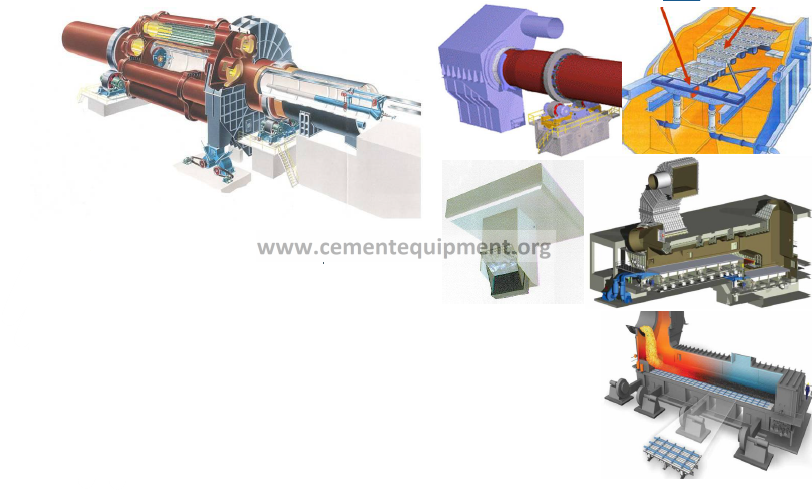
COOLER TYPES
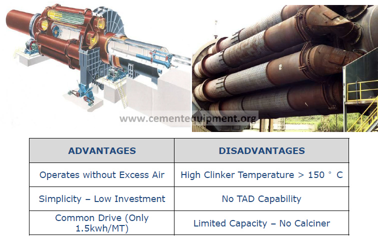
-Planetary cooler
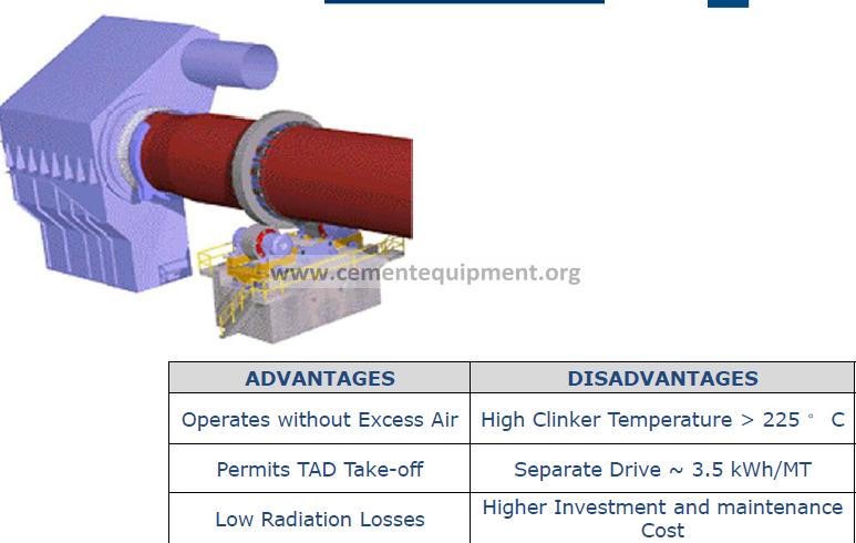
-Rotary cooler
-Grate cooler
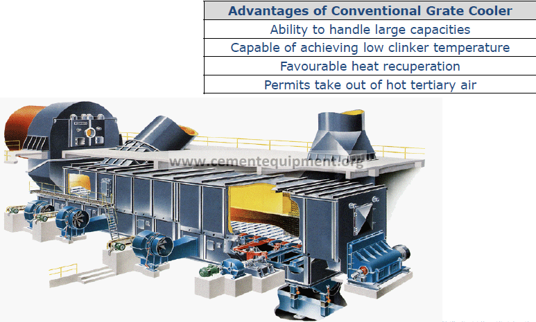
-1st Generation Grate Coolers – conventional grate
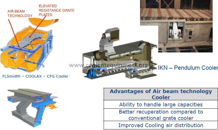
– 2nd Generation Grate Coolers – air-beam grate
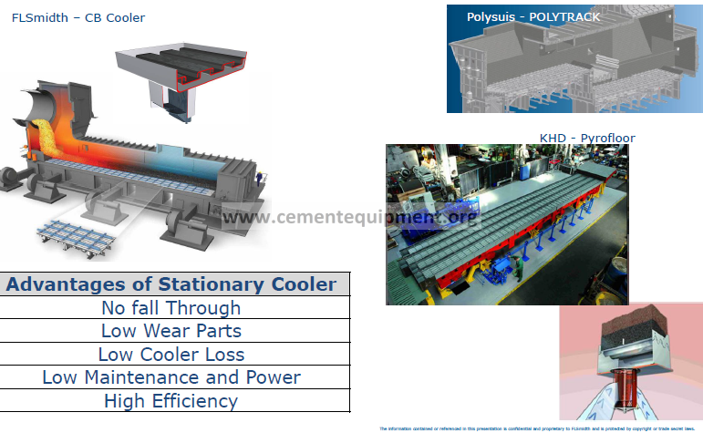
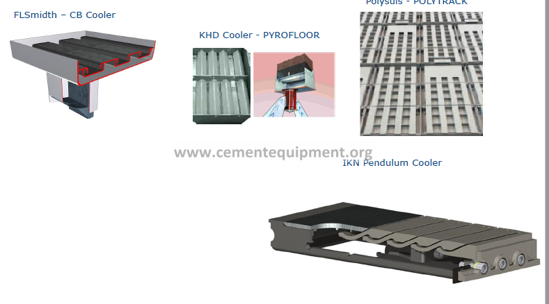
-3rd Generation Grate Coolers – stationary grate
PLANETARY
ROTARY COOLER
1ST GENERATION CONVENTIONAL GRATE COOLERS
2nd GENERATION AIR BEAM
TECHNOLOGY COOLER
3rd GENERATION – STATIONARY GRATE COOLER
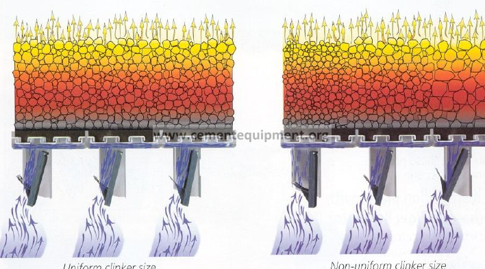
WORKING PRINCIPLE OF COOLER
Grate Plate
FLOW REGULATOR
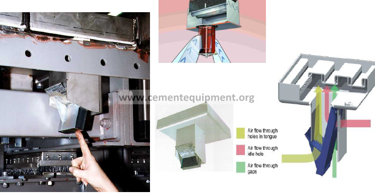
FLOW REGULATOR AND CENVENTIONAL TECHNOLOGY
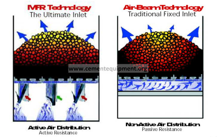
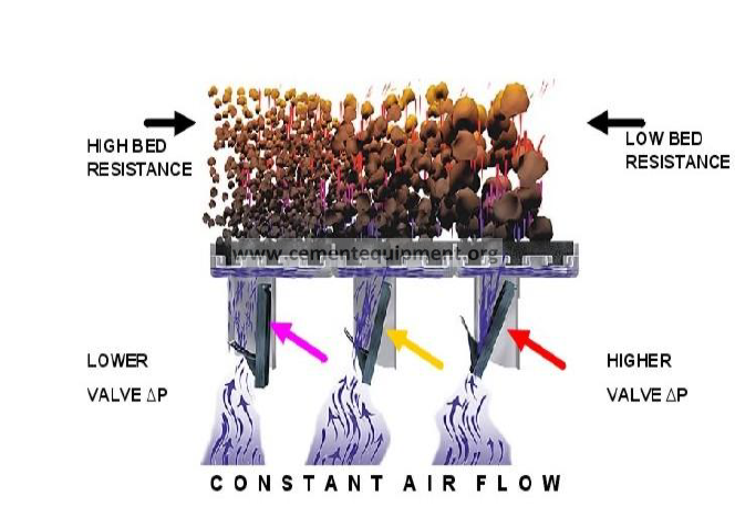
OPERATION OF FLOW REGULATOR
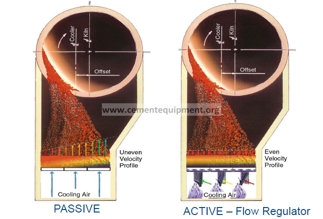
VELOCITY PROFILE COMPARISION
Flow regulator PRESSURE DROP
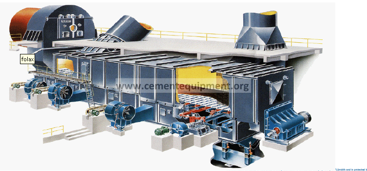
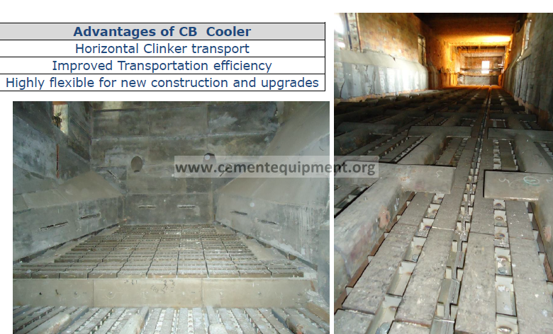
FLSMIDTH CROSS BAR COOLER
MEASUREMENTS & OPTIMISING THE COOLER OPERATION
OPTIMISING THE COOLER
TO ensure the cooler is operated efficiently, the following needs to be monitored
-Cooler Heat Balance.
-Cooler Efficiency.
-Cooler Losses.
COOLER MASS AND HEAT BALANCE
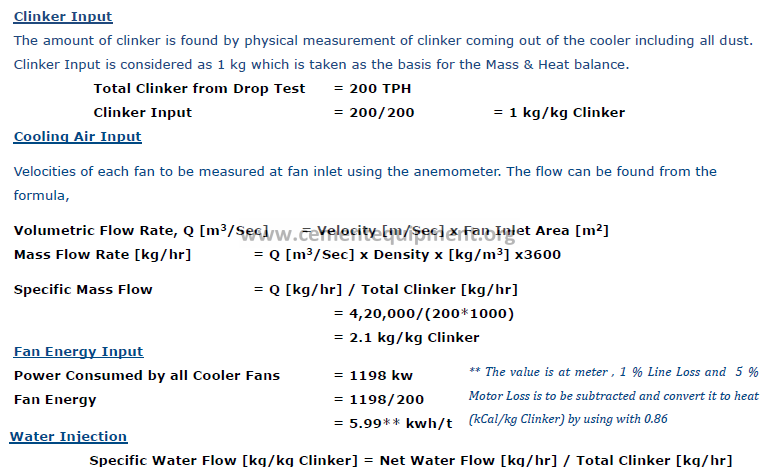
-Cooler Inputs
-Clinker Input
-Cooling Air Input
-Fan Energy Input
-Water Injection
Cooler Outputs
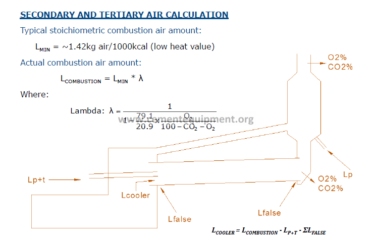
-Secondary and Tertiary Air Calculation
-Excess Air
-Clinker Temperature
-Cooler Radiation
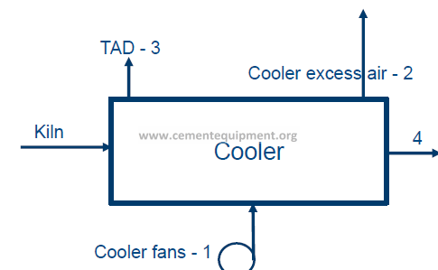
Measurements taken in cooler for cooler heat balance
1.Cooler air fan flow
2.Cooler excess air fan flow – temperature
3.Tertiary air flow – temperature
4.Clinker temperature.
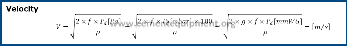
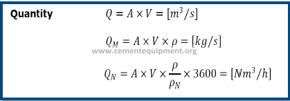
Cooler air fan flow measurement
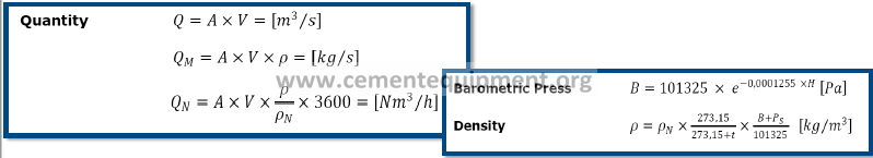
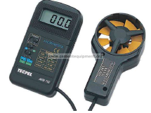
V – Velocity – From Anemometer readings (m/s)
A – Cross Section area of fan inlet area (m2)
ρ – Density of air (kg/m3)
ρN –Density of air at Normal Conditions – 1.293 kg/m3
t – Temperature of ambient air
Ps – Static Pressure at fan inlet
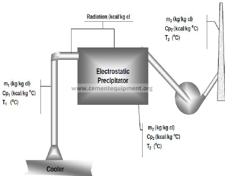
COOLER INPUT
Cooler Excess Air Fan – Flow measurement
-f – Pitot Tube Constant (0.8-0.85)
-Pd – Dynamic Pressure (Pa) – from Pitot Tube Measurement
-g – Acceleration of gravity (m/s2)
-A – Cross Section of duct (m2)
COOLER OUTPUT
EXCESS AIR
The cooler Excess air can be found by measuring the temperature and static pressure at cooler ESP inlet or ESP fan inlet or at Cooler ESP Stack.
From Stack Cooler Excess air will be found by back calculation as follows.
1. Gas inlet condition
2. Leak air inlet condition
3. Gas outlet condition
Clinker Temperature
Clinker temperature is to be measured by taking clinker samples in an insulated closed container.
Clinker considered for measurement must be sieved in – 12 mm and + 6 mm sieves.
Coating pieces and red hot pieces must be removed.
It is recommended to take the samples before Clinker crusher.
This is mainly because coating pieces will be crushed in clinker crusher zone and this must be avoided.
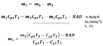
Cooler Radiation
Cooler radiation is calculated from the surface temperature and surface area.
In general cooler radiation for modern cooler will be around 6 kcal/kg Clinker
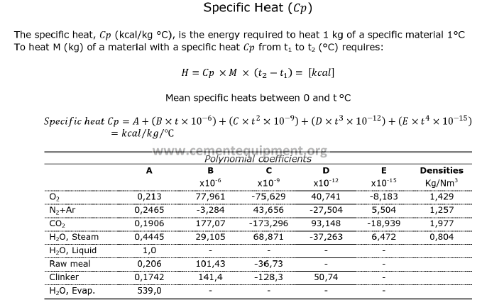
Specific heat calculation (Cp)
Summary of measurements
-Cooler input air – Mass – Temperature
-Cooler excess air – Mass – Temperature
-Tertiary Air – Temperature
-Clinker temperature at cooler outlet
-Fan Energy
Summary of calculation
-Secondary and tertiary air – Mass / Flow
-Radiation loss
-Specific heat of all parameter with reference to the measured temperature
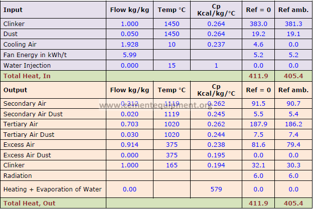
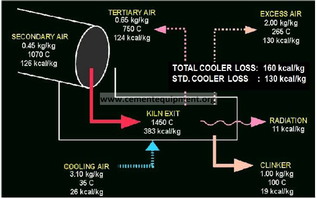
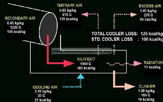
Typical Cooler Mass and Heat Balance
AIR LOAD CALCULATIONS
Cooler Air Load is the ratio of the amount of air supplied to the cooler loading area.
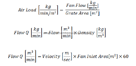
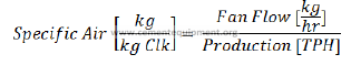
COOLER SPECIFIC AIR
Cooler Specific Air is the ratio of the amount of air supplied to the clinker production.
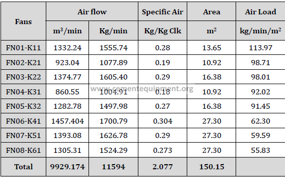
EXAMPLE FOR AIR LOAD AND SPECIFIC AIR
Here is an example of air load calculation for a complete cooler.
Kiln Feed = 550 TPH
Kiln Production=8049 TPD
Density= 1.167 kg/m3
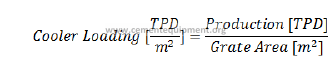
COOLER LOADING
The cooler loading is defined as the amount of clinker over the grate area.
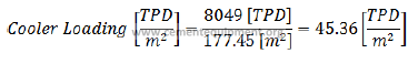
Cooler Loading for the above example is calculated as
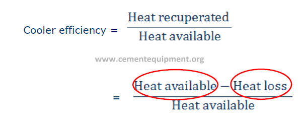
COOLER EFFICIENCY
Better Clinker quality
Higher cooler efficiency – Lower specific fuel consumption
Other Indirect benefits …
Reduction in PH fan power consumption
Lower clinker temperature – Handling clinker shall be much more easier
The efficiency of a cooler is defined as the relationship between the recuperated heat to the kiln and the total heat transferred to the cooler.
Where,
Cooler Loss = (TKO x SKTKO) + (MEX x TEX x SATEX) + RA
TKO = Temperature of clinker leaving the cooler
SKTKO = Specific Heat of Clinker leaving the cooler
MEX = kg of excess air per kg of clinker
TEX = Temperature of excess air
SATEX = Specific heat of excess air
MCA = kg of cooling air per kg of clinker
TCA = Temperature of cooling air
SATCA = Specific heat of cooling air
RA = Cooler housing radiation in kcal/kg of clinker
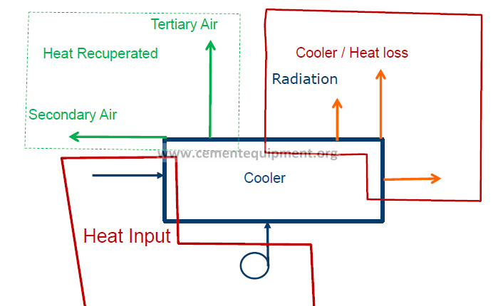
What is Cooler efficiency???
Heat Available / Heat Input
• Heat content of clinker from kiln (Clinker–1450°C)
• Heat content of cooler air (ambient air)

Heat loss
-Heat content of cooler vent gas
-Radiation
-Heat content of clinker at exit
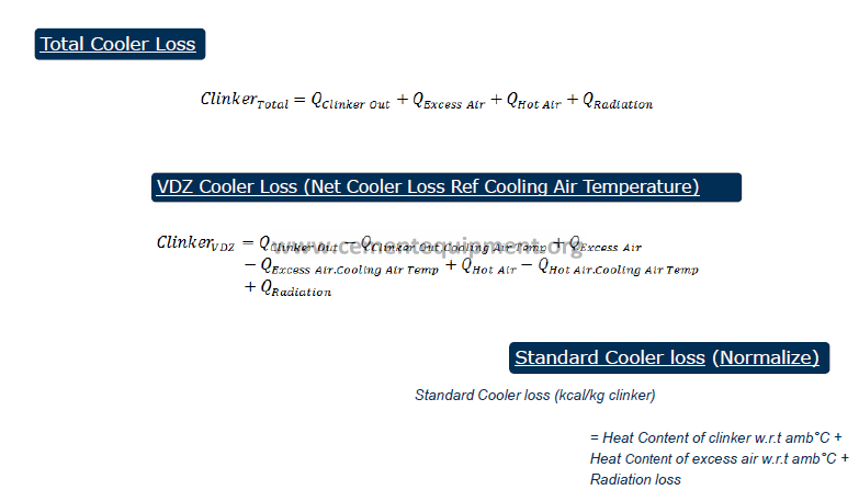
Basis of Cooler loss
-Actual Cooler loss
-VDZ Cooler loss
-Standard Cooler loss
Actual Cooler loss (ref 0°C)
Actual Cooler loss = Heat Content of clinker at 0°C
+
Heat Content of excess air at 0°C
+
Radiation loss
VDZ Cooler loss (ref ambient air °C)
VDZ Cooler loss = Heat Content of clinker w.r.t amb°C
+
Heat Content of excess air w.r.t amb°C
+
Radiation loss
Verein Deutscher Zementwerke – German Cement Works Association
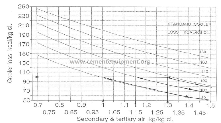
Standard Cooler loss (ref ambient air °C)
Standard Cooler loss (kcal/kg clinker)
= Heat Content of clinker w.r.t amb°C +
Heat Content of excess air w.r.t amb°C +
Radiation loss
Standard Cooler loss basis
•Combustion air – 1.15 kg/kg clk
OVERALL COMPARISON
ACTUAL LOSS Vs STANDARD LOSS
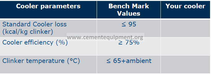
Summary of cooler performance
-Cooler loss – From heat balance
-Cooler efficiency – From formula
-Clinker temperature – From measurement
Possible reasons for cooler inefficiency
Grate plates worn out (Applicable for 2nd generation cooler)
Insufficient cooler air
Clinker bed – not optimum
Too high cooler width / grate load
Clinker PSD – Too fine clinker – This shall lead to red river, if not cooled initially.
Clinker chemistry
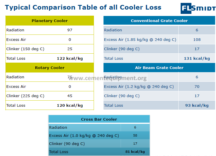
COOLER LOSS – A TYPICAL COMPARISION STUDY
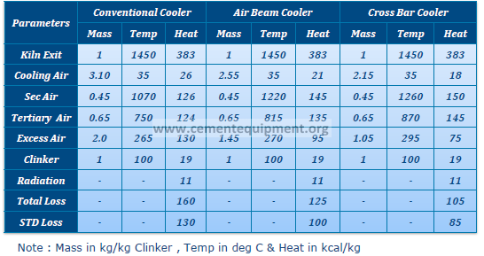
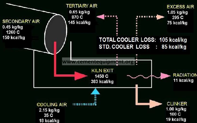
All the three coolers has the same combustion air but the cooler loss reduced by 55 kcal/kg in Cross Bar cooler when compared to conventional cooler.
The excess air which is the major loss in cooler is reduced to 1 kg/kg Clinker and where as heat reduced to heat 75 kcal/kg.
The Cooling air input is reduced from 3.10 to 2.15 kg/kg Clinker
EXAMPLE
For clear understanding this can be discussed with an example.
Let’s consider, P = 200 TPH, NCV = 5500 kcal/kg, then saving in fuel is,
Specific Heat Saving = Conventional Cooler Loss – SF Cooler Loss
= 160 – 105
= 55 kcal/kg
Heat Saving = 55 x 200 x 1000
= 11 x 106 kcal/hr
Fuel Saved = 11 x 106/5500
= 2000 kg/hr
= 2 tons/hr i.e., 48 tons/day
Assume Cost of 1 ton coal = 53 €
Amount Saved per day = 53 € x 48
= 2,533 € /day
Amount Saved per annum (330 Days) = 76320 € /annum
Note:- It must be noted we have projected only the heat savings. We will have additional savings in electrical consumption because of following reasons. Reduction in input cooling air reduces the number of fans required for fans required for system. Subsequent reduction in excess air quantity will gave some benefits in terms of power savings in cooler vent fan.
1st Generation Cooler
2nd Generation Cooler
3rd Generation Cooler