Very important Notes for Purchasing Managers in cement Factory
these Notes , I collected them and I wrote them in 320 page manual in around 11 years working as purchasing Officer in 3 different cement plants.
if you need any advise about purchasing any part or system in Cement plant please email me and I will help you for Fees less than 150 USD email : [email protected]
1 Purchasing in the Raw Milling section
2 Purchasing in the Preheater section
3 Purchasing in the kiln section
4 Purchasing in the cooler section
5 Purchasing in the kiln &cooler Filters section
6 Purchasing in the kiln BYPASS section
7 Purchasing in the Gas analyzing
8 Purchasing in the kiln coal mill section
9 Purchasing in the cement grinding section
10 Purchasing in the Weighing Dosing
these Notes , I collected them and I wrote them in 320 page manual in around 11 years working as purchasing Officer in 3 different cement plants.
if you need any advise about purchasing any part or system in Cement plant please email me and I will help you for Fees less than 150 USD email : [email protected]
| Raw milling | Best Practice / Recommendation | Specifications | Alternatives | Operating target | Not advisable | Comments | |||||||||||||||||||
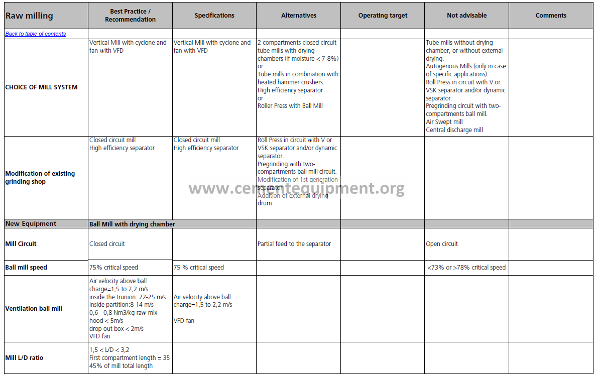
| CHOICE OF MILL SYSTEM | Vertical Mill with cyclone and fan with VFD | Vertical Mill with cyclone and fan with VFD | 2 compartments closed circuit tube mills with drying chambers (if moisture < 7-8%) or Tube mills in combination with heated hammer crushers. High efficiency separator or Roller Press with Ball Mill |
Tube mills without drying chamber, or without external drying. Autogenous Mills (only in case of specific applications). Roll Press in circuit with V or VSK separator and/or dynamic separator. Pregrinding circuit with two- compartments ball mill. Air Swept mill Central discharge mill |
|||||||||||||||||||||
| Modification of existing grinding shop | Closed circuit mill High efficiency separator |
Closed circuit mill High efficiency separator |
Roll Press in circuit with V or VSK separator and/or dynamic separator. Pregrinding with two- compartments ball mill circuit. Modification of 1st generation separator Addition of external drying drum |
||||||||||||||||||||||
| New Equipment | Ball Mill with drying chamber | ||||||||||||||||||||||||
| Mill Circuit | Closed circuit | Partial feed to the separator | Open circuit | ||||||||||||||||||||||
| Ball mill speed | 75% critical speed | 75 % critical speed | <73% or >78% critical speed | ||||||||||||||||||||||
| Ventilation ball mill | Air velocity above ball charge=1,5 to 2,2 m/s inside the trunion: 22-25 m/s inside partition:8-14 m/s 0,6 – 0,8 Nm3/kg raw mix hood < 5m/s drop out box < 2m/s VFD fan |
Air velocity above ball charge=1,5 to 2,2 m/s VFD fan |
|||||||||||||||||||||||
| Mill L/D ratio | 1,5 < L/D < 3,2 First compartment length = 35 45% of mill total length |
||||||||||||||||||||||||
| Raw milling | Best Practice / Recommendation | Specifications | Alternatives | Operating target | Not advisable | Comments | |||||||||||||||||||
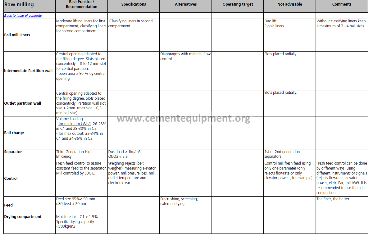
| Ball mill Liners | Moderate lifting liners for first compartment, classifying liners for second compartment | Classifying liners in second compartment | Duo lift Ripple liners | Without classifying liners keep a maximum of 3 – 4 ball sizes | |||||||||||||||||||||
| Intermediate Partition wall | Central opening adapted to the filling degree. Slots placed concentricly. – 8 to 12 mm slot for central partition. – open area > 50 % by central opening |
Diaphragms with material flow control | Slots placed radially. | ||||||||||||||||||||||
| Outlet partition wall | Central opening adapted to the filling degree. Slots placed concentricly. Partition wall slot size + 2mm (max slot = 0,5 min ball size) | Slots placed radially. | |||||||||||||||||||||||
| Ball charge | Volume Loading: – for minimum kWh/t: 26-28% in C1 and 28-30% in C2 – for max output: 32-34% in C1 and 34-36% in C2 |
||||||||||||||||||||||||
| Separator | Third Generation High Efficiency | Dust load < 1kg/m3 Qf/Qa < 2.5 | 1st or 2nd generation separators | ||||||||||||||||||||||
| Control | Fresh feed control to assure constant feed to the separator. Mill controled by LUCIE. | Weighing rejects (belt weigher), measuring elevator power, mill presure loss, mill outlet temperature and electronic ear. | Control mill fresh feed using only one parameter (only rejects flowrate or only elevator power , for example) | Fresh feed control can be done by different ways, using different instruments or signals (rejects flowrate, elevator power, eletr. Ear, mill kW). It is recommended to use them in conjunction. | |||||||||||||||||||||
| Feed | Feed size 95%< 50 mm d80 feed < 20mm, | Precrushing, screening, external drying | The finer, the better | ||||||||||||||||||||||
| Drying compartment | Moisture inlet C1 < 1.5% Specific drying capacity <300kg/m3 |
||||||||||||||||||||||||
| Raw milling | Best Practice / Recommendation | Specifications | Alternatives | Operating target | Not advisable | Comments | |||||||||||||||||||
| Equipment | VRM | ||||||||||||||||||||||||
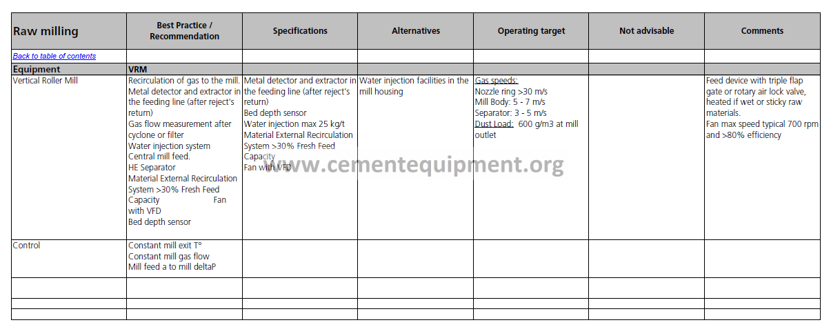
| Vertical Roller Mill | Recirculation of gas to the mill. Metal detector and extractor in the feeding line (after reject’s return) Gas flow measurement after cyclone or filter Water injection system Central mill feed. HE Separator Material External Recirculation System >30% Fresh Feed Capacity Fan with VFD Bed depth sensor |
Metal detector and extractor in the feeding line (after reject’s return) Bed depth sensor Water injection max 25 kg/t Material External Recirculation System >30% Fresh Feed Capacity Fan with VFD |
Water injection facilities in the mill housing | Gas speeds: Nozzle ring >30 m/s Mill Body: 5 – 7 m/s Separator: 3 – 5 m/s Dust Load: 600 g/m3 at mill outlet |
Feed device with triple flap gate or rotary air lock valve, heated if wet or sticky raw materials. Fan max speed typical 700 rpm and >80% efficiency |
||||||||||||||||||||
| Control | Constant mill exit T° Constant mill gas flow Mill feed a to mill deltaP | ||||||||||||||||||||||||
| Preheater | Best practice / Recommendation |
Specifications | Alternatives | Operating target | Not advisable | Comments | |||||||||||||||||||
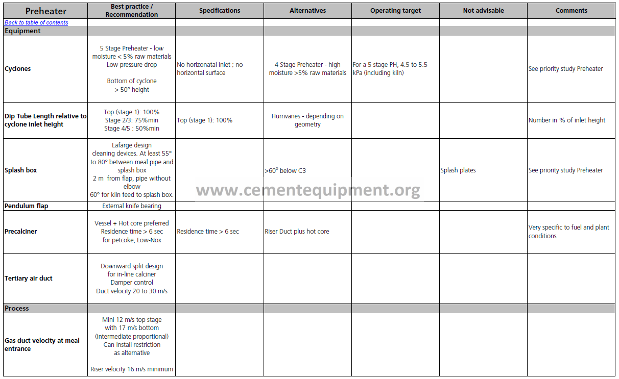
| Equipment | |||||||||||||||||||||||||
| Cyclones | 5 Stage Preheater – low moisture < 5% raw materials Low pressure drop Bottom of cyclone > 50° height |
No horizonatal inlet ; no horizontal surface | 4 Stage Preheater – high moisture >5% raw materials | For a 5 stage PH, 4.5 to 5.5 kPa (including kiln) | See priority study Preheater | ||||||||||||||||||||
| Dip Tube Length relative to cyclone inlet height | Top (stage 1): 100% Stage 2/3: 75%min Stage 4/5 : 50%min | Top (stage 1): 100% | Hurrivanes – depending on geometry | Number in % of inlet height | |||||||||||||||||||||
| Splash box | Lafarge design cleaning devices. At least 55° to 80° between meal pipe and splash box 2 m from flap, pipe without elbow 60° for kiln feed to splash box. |
>60o below C3 | Splash plates | See priority study Preheater | |||||||||||||||||||||
| Pendulum flap | External knife bearing | ||||||||||||||||||||||||
| Precalciner | Vessel + Hot core preferred Residence time > 6 sec for petcoke, Low-Nox | Residence time > 6 sec | Riser Duct plus hot core | Very specific to fuel and plant conditions | |||||||||||||||||||||
| Tertiary air duct | Downward split design for in-line calciner Damper control Duct velocity 20 to 30 m/s |
||||||||||||||||||||||||
| Process | |||||||||||||||||||||||||
| Gas duct velocity at meal entrance | Mini 12 m/s top stage with 17 m/s bottom (intermediate proportional) Can install restriction as alternative Riser velocity 16 m/s minimum |
||||||||||||||||||||||||
| Preheater | Best practice / Recommendation |
Specifications | Alternatives | Operating target | Not advisable | Comments | |||||||||||||||||||
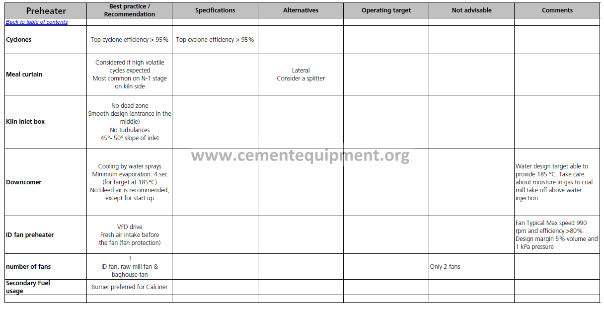
| Cyclones | Top cyclone efficiency > 95% | Top cyclone efficiency > 95% | |||||||||||||||||||||||
| Meal curtain | Considered if high volatile cycles expected Most common on N-1 stage on kiln side |
Lateral Consider a splitter | |||||||||||||||||||||||
| Kiln inlet box | No dead zone Smooth design (entrance in the middle) No turbulances 45°- 50° slope of inlet |
||||||||||||||||||||||||
| Downcomer | Cooling by water sprays Minimum evaporation: 4 sec (for target at 185°C) No bleed air is recommended, except for start up |
Water design target able to provide 185 °C. Take care about moisture in gas to coal mill take off above water injection | |||||||||||||||||||||||
| ID fan preheater | VFD drive Fresh air intake before the fan (fan protection) |
Fan Typical Max speed 990 rpm and efficiency >80%. Design margin 5% volume and 1 kPa pressure | |||||||||||||||||||||||
| number of fans | 3 ID fan, raw mill fan & baghouse fan |
Only 2 fans | |||||||||||||||||||||||
| Secondary Fuel usage |
Burner preferred for Calciner | ||||||||||||||||||||||||
| Kiln | Best Practice / Recommendation |
Specifications | Alternatives | Operating target | Not advisable | Comments | |||||||||||||||||||
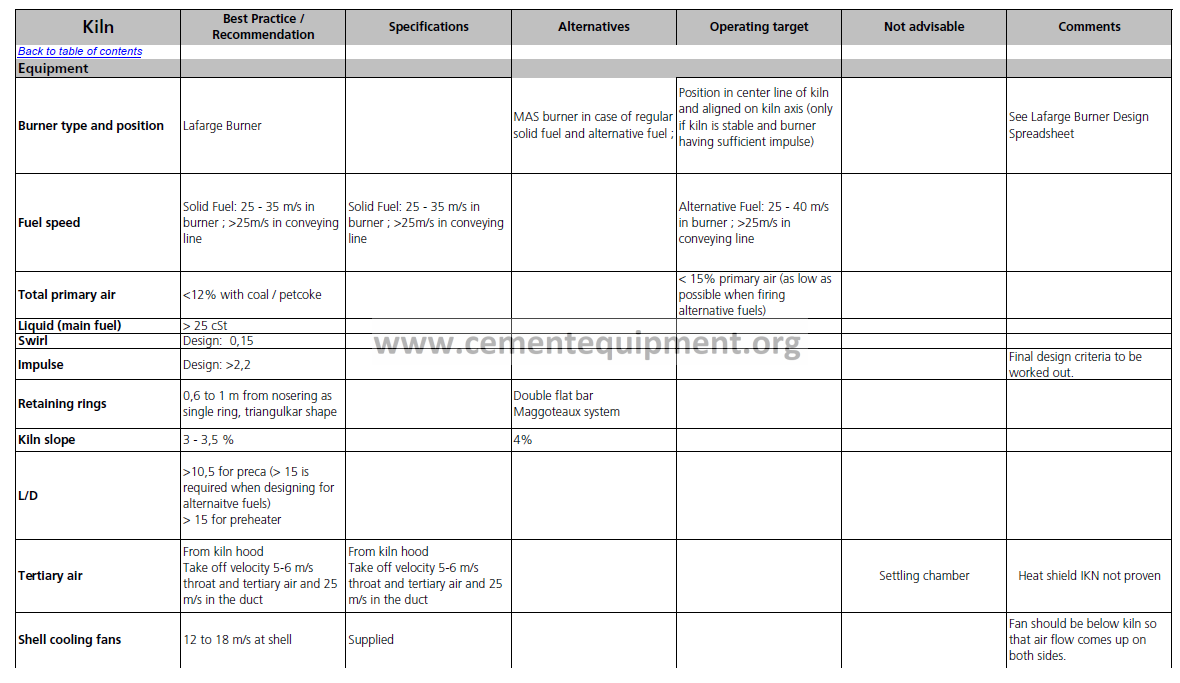
| Equipment | |||||||||||||||||||||||||
| Burner type and position | Lafarge Burner | MAS burner in case of regular solid fuel and alternative fuel ; | Position in center line of kiln and aligned on kiln axis (only if kiln is stable and burner having sufficient impulse) | See Lafarge Burner Design Spreadsheet | |||||||||||||||||||||
| Fuel speed | Solid Fuel: 25 – 35 m/s in burner ; >25m/s in conveying line | Solid Fuel: 25 – 35 m/s in burner ; >25m/s in conveying line | Alternative Fuel: 25 – 40 m/s in burner ; >25m/s in conveying line | ||||||||||||||||||||||
| Total primary air | <12% with coal / petcoke | < 15% primary air (as low as possible when firing alternative fuels) |
|||||||||||||||||||||||
| Liquid (main fuel) | > 25 cSt | ||||||||||||||||||||||||
| Swirl | Design: 0,15 | ||||||||||||||||||||||||
| Impulse | Design: >2,2 | Final design criteria to be worked out. |
|||||||||||||||||||||||
| Retaining rings | 0,6 to 1 m from nosering as single ring, triangulkar shape | Double flat bar Maggoteaux system | |||||||||||||||||||||||
| Kiln slope | 3 – 3,5 % | 4% | |||||||||||||||||||||||
| L/D | >10,5 for preca (> 15 is required when designing for alternaitve fuels) > 15 for preheater |
||||||||||||||||||||||||
| Tertiary air | From kiln hood Take off velocity 5-6 m/s throat and tertiary air and 25 m/s in the duct |
From kiln hood Take off velocity 5-6 m/s throat and tertiary air and 25 m/s in the duct |
Settling chamber | Heat shield IKN not proven | |||||||||||||||||||||
| Shell cooling fans | 12 to 18 m/s at shell | Supplied | Fan should be below kiln so that air flow comes up on both sides. | ||||||||||||||||||||||
| Kiln | Best Practice / Recommendation |
Specifications | Alternatives | Operating target | Not advisable | Comments | |||||||||||||||||||
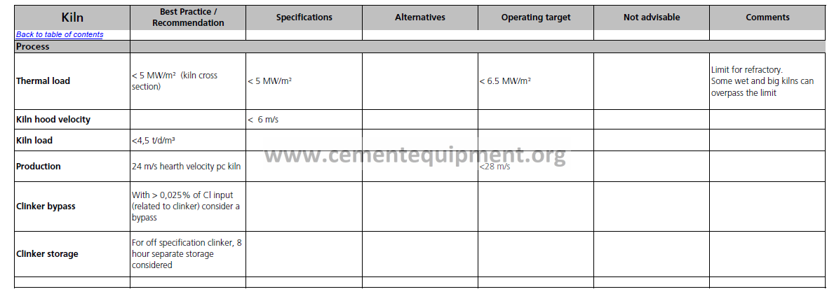
| Process | |||||||||||||||||||||||||
| Thermal load | < 5 MW/m² (kiln cross section) | < 5 MW/m² | < 6.5 MW/m² | Limit for refractory. Some wet and big kilns can overpass the limit |
|||||||||||||||||||||
| Kiln hood velocity | < 6 m/s | ||||||||||||||||||||||||
| Kiln load | <4,5 t/d/m³ | ||||||||||||||||||||||||
| Production | 24 m/s hearth velocity pc kiln | <28 m/s | |||||||||||||||||||||||
| Clinker bypass | With > 0,025% of Cl input (related to clinker) consider a bypass | ||||||||||||||||||||||||
| Clinker storage | For off specification clinker, 8 hour separate storage considered | ||||||||||||||||||||||||
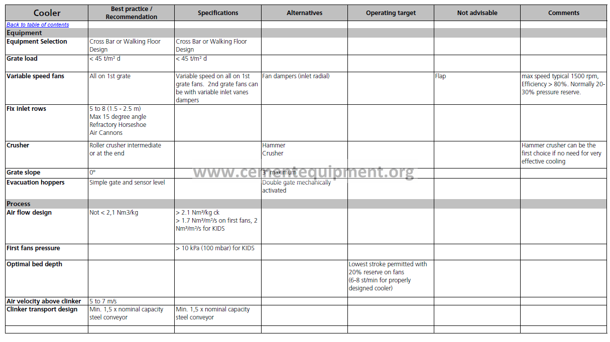
| Cooler | Best practice / Recommendation |
Specifications | Alternatives | Operating target | Not advisable | Comments | |||||||||||||||||||
| Equipment | |||||||||||||||||||||||||
| Equipment Selection | Cross Bar or Walking Floor Design |
Cross Bar or Walking Floor Design |
|||||||||||||||||||||||
| Grate load | < 45 t/m² d | < 45 t/m² d | |||||||||||||||||||||||
| Variable speed fans | All on 1st grate | Variable speed on all on 1st grate fans. 2nd grate fans can be with variable inlet vanes dampers |
Fan dampers (inlet radial) | Flap | max speed typical 1500 rpm, Efficiency > 80%. Normally 20- 30% pressure reserve. |
||||||||||||||||||||
| Fix inlet rows | 5 to 8 (1.5 – 2.5 m) Max 15 degree angle Refractory Horseshoe Air Cannons |
||||||||||||||||||||||||
| Crusher | Roller crusher intermediate or at the end | Hammer Crusher | Hammer crusher can be the first choice if no need for very effective cooling | ||||||||||||||||||||||
| Grate slope | 0° | 3° maximum | |||||||||||||||||||||||
| Evacuation hoppers | Simple gate and sensor level | Double gate mechanically activated | |||||||||||||||||||||||
| Process | |||||||||||||||||||||||||
| Air flow design | Not < 2,1 Nm3/kg | > 2.1 Nm³/kg ck > 1.7 Nm³/m²/s on first fans, 2 Nm³/m²/s for KIDS |
|||||||||||||||||||||||
| First fans pressure | > 10 kPa (100 mbar) for KIDS | ||||||||||||||||||||||||
| Optimal bed depth | Lowest stroke permitted with 20% reserve on fans (6-8 st/min for properly designed cooler) |
||||||||||||||||||||||||
| Air velocity above clinker | 5 to 7 m/s | ||||||||||||||||||||||||
| Clinker transport design | Min. 1,5 x nominal capacity steel conveyor | Min. 1,5 x nominal capacity steel conveyor | |||||||||||||||||||||||
| Process guidelines – Cooler – Page 1 / 1 06/10/2005 – 10:59 | |||||||||||||||||||||||||
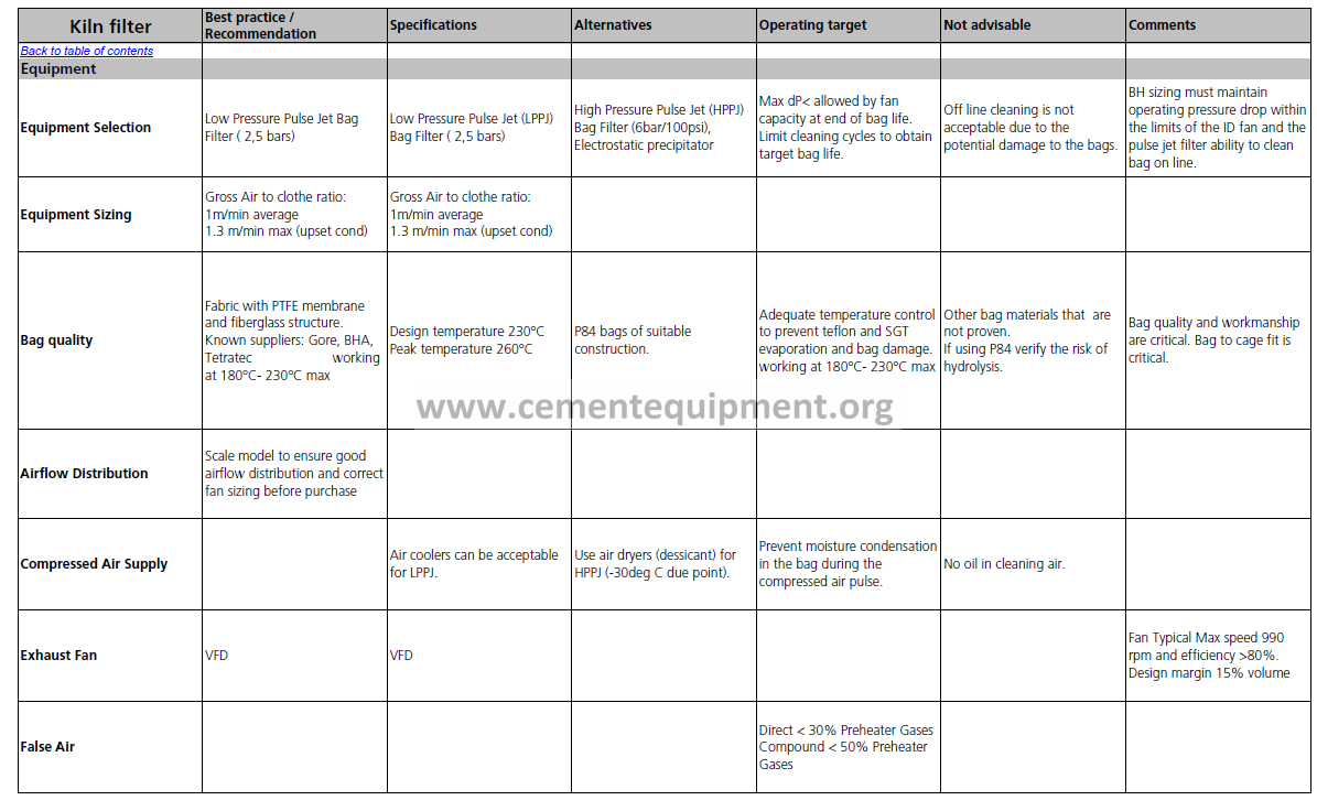
| Kiln filter | Best practice / Recommendation |
Specifications | Alternatives | Operating target | Not advisable | Comments | |||||||||||||||||||
| Equipment | |||||||||||||||||||||||||
| Equipment Selection | Low Pressure Pulse Jet Bag Filter ( 2,5 bars) | Low Pressure Pulse Jet (LPPJ) Bag Filter ( 2,5 bars) | High Pressure Pulse Jet (HPPJ) Bag Filter (6bar/100psi), Electrostatic precipitator | Max dP< allowed by fan capacity at end of bag life. Limit cleaning cycles to obtain target bag life. | Off line cleaning is not acceptable due to the potential damage to the bags. | BH sizing must maintain operating pressure drop within the limits of the ID fan and the pulse jet filter ability to clean bag on line. | |||||||||||||||||||
| Equipment Sizing | Gross Air to clothe ratio: 1m/min average 1.3 m/min max (upset cond) |
Gross Air to clothe ratio: 1m/min average 1.3 m/min max (upset cond) |
|||||||||||||||||||||||
| Bag quality | Fabric with PTFE membrane and fiberglass structure. Known suppliers: Gore, BHA, Tetratec working at 180°C- 230°C max |
Design temperature 230°C Peak temperature 260°C | P84 bags of suitable construction. | Adequate temperature control to prevent teflon and SGT evaporation and bag damage. working at 180°C- 230°C max | Other bag materials that are not proven. If using P84 verify the risk of hydrolysis. |
Bag quality and workmanship are critical. Bag to cage fit is critical. | |||||||||||||||||||
| Airflow Distribution | Scale model to ensure good airflow distribution and correct fan sizing before purchase | ||||||||||||||||||||||||
| Compressed Air Supply | Air coolers can be acceptable for LPPJ. | Use air dryers (dessicant) for HPPJ (-30deg C due point). | Prevent moisture condensation in the bag during the compressed air pulse. | No oil in cleaning air. | |||||||||||||||||||||
| Exhaust Fan | VFD | VFD | Fan Typical Max speed 990 rpm and efficiency >80%. Design margin 15% volume | ||||||||||||||||||||||
| False Air | Direct < 30% Preheater Gases Compound < 50% Preheater Gases | ||||||||||||||||||||||||
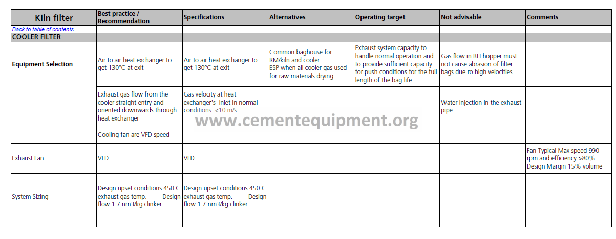
| Kiln filter | Best practice / Recommendation |
Specifications | Alternatives | Operating target | Not advisable | Comments | |||||||||||||||||||
| COOLER FILTER | |||||||||||||||||||||||||
| Equipment Selection | Air to air heat exchanger to get 130°C at exit | Air to air heat exchanger to get 130°C at exit | Common baghouse for RM/kiln and cooler ESP when all cooler gas used for raw materials drying |
Exhaust system capacity to handle normal operation and to provide sufficient capacity for push conditions for the full length of the bag life. | Gas flow in BH hopper must not cause abrasion of filter bags due ro high velocities. | ||||||||||||||||||||
| Exhaust gas flow from the cooler straight entry and oriented downwards through heat exchanger | Gas velocity at heat exchanger’s inlet in normal conditions: <10 m/s | Water injection in the exhaust pipe | |||||||||||||||||||||||
| Cooling fan are VFD speed | |||||||||||||||||||||||||
| Exhaust Fan | VFD | VFD | Fan Typical Max speed 990 rpm and efficiency >80%. Design Margin 15% volume | ||||||||||||||||||||||
| System Sizing | Design upset conditions 450 C exhaust gas temp. Design flow 1.7 nm3/kg clinker | Design upset conditions 450 C exhaust gas temp. Design flow 1.7 nm3/kg clinker | |||||||||||||||||||||||
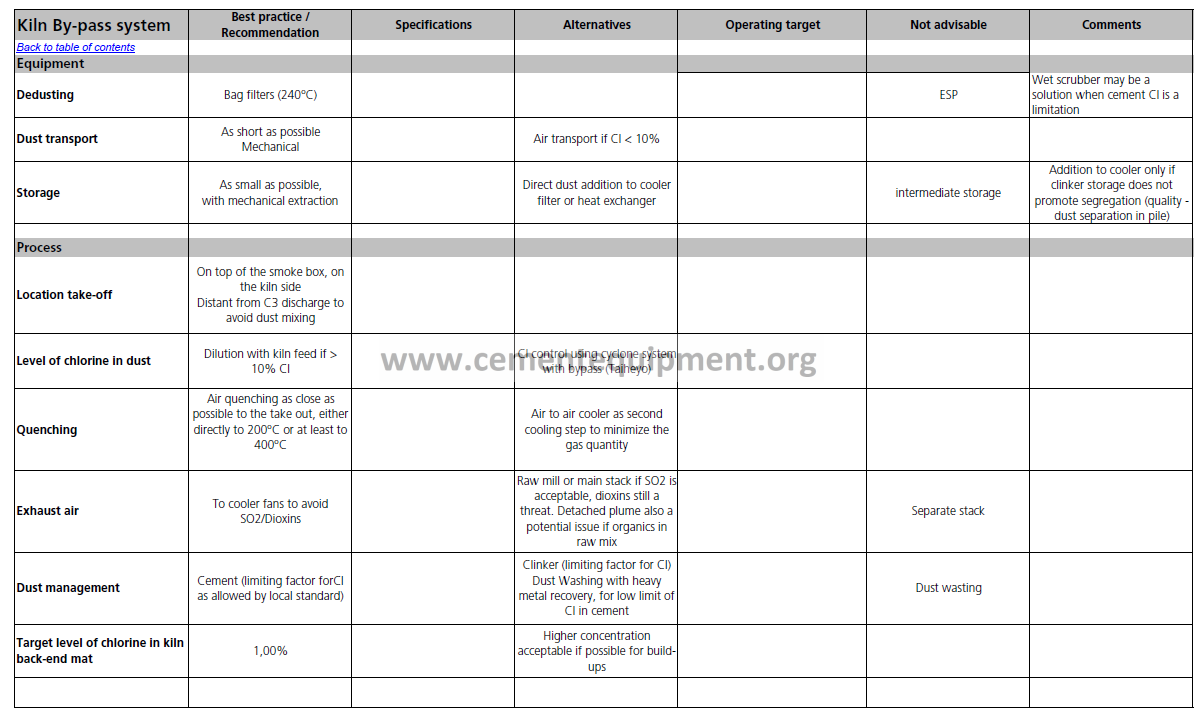
| Kiln By-pass system | Best practice / Recommendation |
Specifications | Alternatives | Operating target | Not advisable | Comments | |||||||||||||||||||
| Equipment | |||||||||||||||||||||||||
| Dedusting | Bag filters (240°C) | ESP | Wet scrubber may be a solution when cement Cl is a limitation |
||||||||||||||||||||||
| Dust transport | As short as possible Mechanical | Air transport if Cl < 10% | |||||||||||||||||||||||
| Storage | As small as possible, with mechanical extraction | Direct dust addition to cooler filter or heat exchanger | intermediate storage | Addition to cooler only if clinker storage does not promote segregation (quality – dust separation in pile) |
|||||||||||||||||||||
| Process | |||||||||||||||||||||||||
| Location take-off | On top of the smoke box, on the kiln side Distant from C3 discharge to avoid dust mixing |
||||||||||||||||||||||||
| Level of chlorine in dust | Dilution with kiln feed if > 10% Cl | Cl control using cyclone system with bypass (Taiheyo) | |||||||||||||||||||||||
| Quenching | Air quenching as close as possible to the take out, either directly to 200°C or at least to 400°C | Air to air cooler as second cooling step to minimize the gas quantity | |||||||||||||||||||||||
| Exhaust air | To cooler fans to avoid SO2/Dioxins | Raw mill or main stack if SO2 is acceptable, dioxins still a threat. Detached plume also a potential issue if organics in raw mix | Separate stack | ||||||||||||||||||||||
| Dust management | Cement (limiting factor forCl as allowed by local standard) | Clinker (limiting factor for Cl) Dust Washing with heavy metal recovery, for low limit of Cl in cement | Dust wasting | ||||||||||||||||||||||
| Target level of chlorine in kiln back-end mat | 1,00% | Higher concentration acceptable if possible for build- ups | |||||||||||||||||||||||
| Process guidelines – Kiln By-pass system – Page 1 / 1 06/10/2005 – 10:59 | |||||||||||||||||||||||||
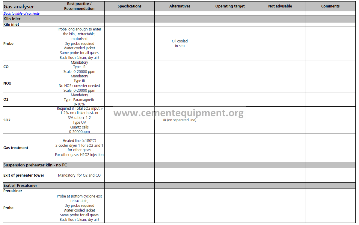
| Gas analyser | Best practice / Recommendation |
Specifications | Alternatives | Operating target | Not advisable | Comments | |||||||||||||||||||
| Kiln inlet | |||||||||||||||||||||||||
| Kiln inlet | |||||||||||||||||||||||||
| Probe | Probe long enough to enter the kiln, retractable, motorised Dry probe required Water cooled jacket Same probe for all gases Back flush (clean, dry air) |
Oil cooled In-situ | |||||||||||||||||||||||
| CO | Mandatory Type: IR Scale: 0-20000 ppm |
||||||||||||||||||||||||
| NOx | Mandatory Type IR No NO2 converter needed Scale: 0-20000 ppm |
||||||||||||||||||||||||
| O2 | Mandatory Type: Paramagnetic 0-10% |
||||||||||||||||||||||||
| SO2 | Required if Total SO3 input > 1.2% on clinker basis or S/A ratio > 1.2 Type UV Quartz cells 0-20000ppm |
IR (on separated line) | |||||||||||||||||||||||
| Gas treatment | Heated line (>180°C) 2 cooler dryer 1 for SO2 and 1 for other gases For other gases H2O2 injection |
||||||||||||||||||||||||
| Suspension preheater kiln – no PC | |||||||||||||||||||||||||
| Exit of preheater tower | Mandatory for O2 and CO | ||||||||||||||||||||||||
| Exit of Precalciner | |||||||||||||||||||||||||
| Precalciner | |||||||||||||||||||||||||
| Probe | Probe at Bottom cyclone exit retractable, Dry probe required Water cooled jacket Same probe for all gases Back flush (clean, dry air) |
||||||||||||||||||||||||
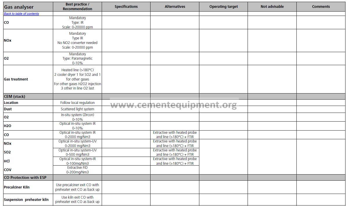
| Gas analyser | Best practice / Recommendation |
Specifications | Alternatives | Operating target | Not advisable | Comments | |||||||||||||||||||
| CO | Mandatory Type: IR Scale: 0-20000 ppm |
||||||||||||||||||||||||
| NOx | Mandatory Type IR No NO2 converter needed Scale: 0-20000 ppm |
||||||||||||||||||||||||
| O2 | Mandatory Type: Paramagnetic 0-10% |
||||||||||||||||||||||||
| Gas treatment | Heated line (>180°C) 2 cooler dryer 1 for SO2 and 1 for other gases For other gases H2O2 injection 3 other in line O2 last |
||||||||||||||||||||||||
| CEM (stack) | |||||||||||||||||||||||||
| Location | Follow local regulation | ||||||||||||||||||||||||
| Dust | Scattered light system | ||||||||||||||||||||||||
| O2 | In-situ system (Zircon) 0-10% |
||||||||||||||||||||||||
| H2O | Optical in-situ system IR 0-10% |
||||||||||||||||||||||||
| CO | Optical in-situ system IR 0-2000 mg/Nm3 |
Extractive with heated probe and line (>180°C) + FTIR |
|||||||||||||||||||||||
| NOx SO2 HCl COV |
Optical in-situ system-UV 0-2000 mg/Nm3 |
Extractive with heated probe and line (>180°C) + FTIR |
|||||||||||||||||||||||
| Optical in-situ system-UV 0-500 mg/Nm3 |
Extractive with heated probe and line (>180°C) + FTIR |
||||||||||||||||||||||||
| Optical in-situ system-IR 0-100mg/Nm3 |
Extractive with heated probe and line (>180°C) + FTIR |
||||||||||||||||||||||||
| Extractive FID 0-200mg/Nm3 |
|||||||||||||||||||||||||
| CO Protection with ESP | |||||||||||||||||||||||||
| Precalciner Kiln | Use precalciner exit CO with preheater exit CO as back up | ||||||||||||||||||||||||
| Suspension preheater kiln | Use kiln exit CO with preheater exit CO as back up | ||||||||||||||||||||||||
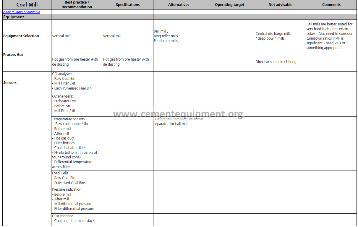
| Coal Mill | Best practice / Recommendation |
Specifications | Alternatives | Operating target | Not advisable | Comments | |||||||||||||||||||
| Equipment | |||||||||||||||||||||||||
| Equipment Selection | Vertical mill | Vertical mill | Ball mill , Ring roller mills Pendulum mills |
Central discharge mills “deep bowl” mills | Ball mills are better suited for very hard fuels and certain cokes. Also need to consider turndown ratios if AF is significant – need VFD or something appropriate. | ||||||||||||||||||||
| Process Gas | Hot gas from pre heater with de dusting | Hot gas from pre heater with de dusting | Direct or semi direct firing | ||||||||||||||||||||||
| Sensors | CO analysers: – Raw Coal Bin – Mill Filter Exit – Each Pulverised Fuel Bin |
||||||||||||||||||||||||
| O2 analysers: – Preheater Exit – Before Mill – Mill Filter Exit |
|||||||||||||||||||||||||
| Temperature sensors – Raw coal hopper/silo – Before mill – After mill – Hot gas duct – Filter bottom – Coal dust after filter – PF silo bottom ( In banks of four around cone) – Differential temperature across filter |
Differential temperature across separator for ball mill | ||||||||||||||||||||||||
| Load Cells – Raw Coal Bin – Pulverised Coal Bins |
|||||||||||||||||||||||||
| Pressure indication – Before mill – After mill – Mill differential pressure – Filter differential pressure |
|||||||||||||||||||||||||
| Dust monitor – Coal bag filter main stack |
|||||||||||||||||||||||||
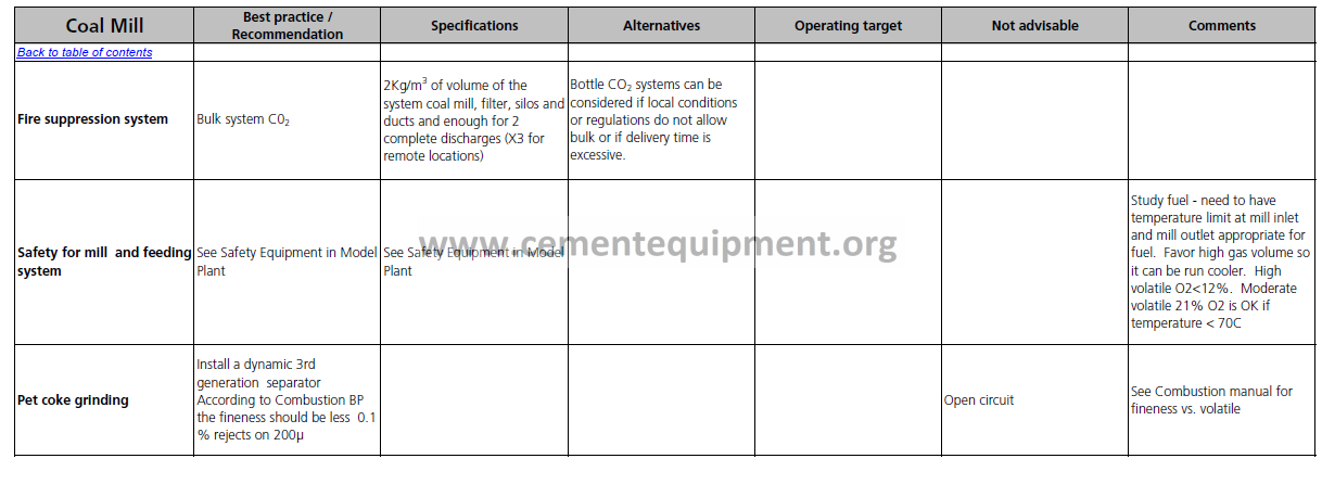
| Coal Mill | Best practice / Recommendation |
Specifications | Alternatives | Operating target | Not advisable | Comments | |||||||||||||||||||
| Fire suppression system | Bulk system C02 | 2Kg/m3 of volume of the system coal mill, filter, silos and ducts and enough for 2 complete discharges (X3 for remote locations) | Bottle CO2 systems can be considered if local conditions or regulations do not allow bulk or if delivery time is excessive. | ||||||||||||||||||||||
| Safety for mill and feeding system | See Safety Equipment in Model Plant | See Safety Equipment in Model Plant | Study fuel – need to have temperature limit at mill inlet and mill outlet appropriate for fuel. Favor high gas volume so it can be run cooler. High volatile O2<12%. Moderate volatile 21% O2 is OK if temperature < 70C | ||||||||||||||||||||||
| Pet coke grinding | Install a dynamic 3rd generation separator According to Combustion BP the fineness should be less 0.1 % rejects on 200µ |
Open circuit | See Combustion manual for fineness vs. volatile | ||||||||||||||||||||||
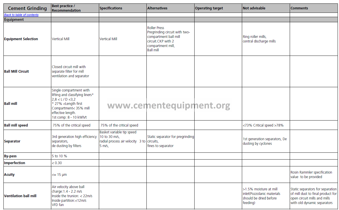
| Cement Grinding | Best practice / Recommendation |
Specifications | Alternatives | Operating target | Not advisable | Comments | |||||||||||||||||||
| Equipment | |||||||||||||||||||||||||
| Equipment Selection | Vertical Mill | Vertical Mill | Roller Press Pregrinding circuit with two- compartment ball mill circuit.CKP with 2 compartment mill, Ball mill |
Ring roller mills, central discharge mills | |||||||||||||||||||||
| Ball Mill Circuit | Closed circuit mill with separate filter for mill ventilation and separator | ||||||||||||||||||||||||
| Ball mill | Single compartment with lifting and classifying liners* 2,8 < L / D <3,2 * 27% <Length first Compartment< 35% mill effective length. 1st comp: 8 – 10 kWh/t |
||||||||||||||||||||||||
| Ball mill speed | 75% of the critical speed | 75% of the critical speed | <73% Critical speed >78% | ||||||||||||||||||||||
| Separator | 3rd generation high efficiency separators, de dusting by filters |
Basket variable tip speed 10 to 30 m/s, radial process air velocity 3 to 5 m/s, |
Static separator for pregrinding circuits, fines to separator |
1st generation separators, De dusting by cyclones | |||||||||||||||||||||
| By-pass | 5 to 10 % | ||||||||||||||||||||||||
| Imperfection | < 0.30 | ||||||||||||||||||||||||
| Acuity | <= 15 µm | Rosin Rammler specification value to be provided | |||||||||||||||||||||||
| Ventilation ball mill | Air velocity above ball charge:1.4 – 2.2 m/s Inside the trunion: < 22m/s Inside partition:<12m/s VFD fan |
>1.5% moisture at mill inlet(Pozzolanic materials should be dried before feeding) | Static separators for separation of mill dust to final product for open circuit mills and mills with old dynamic separators | ||||||||||||||||||||||
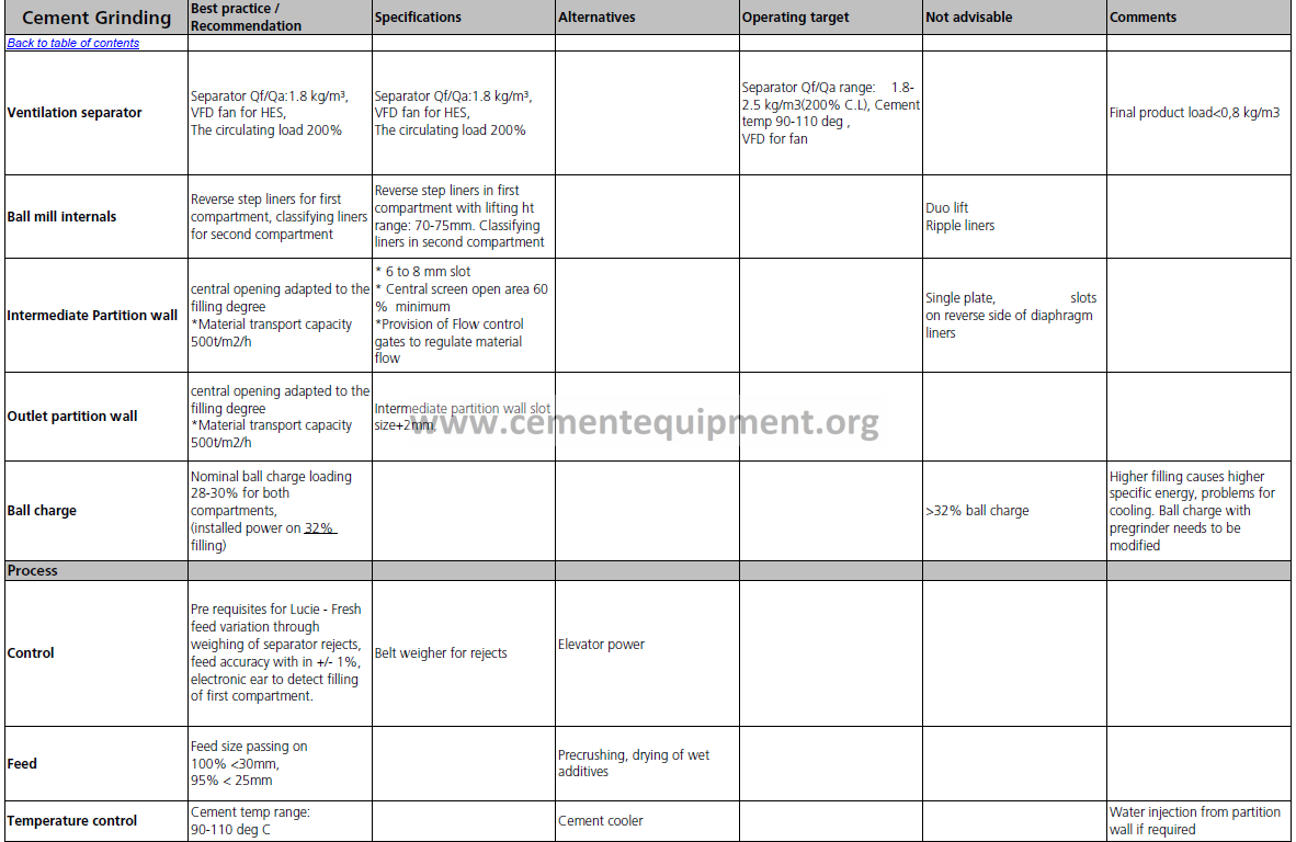
| Cement Grinding | Best practice / Recommendation |
Specifications | Alternatives | Operating target | Not advisable | Comments | |||||||||||||||||||
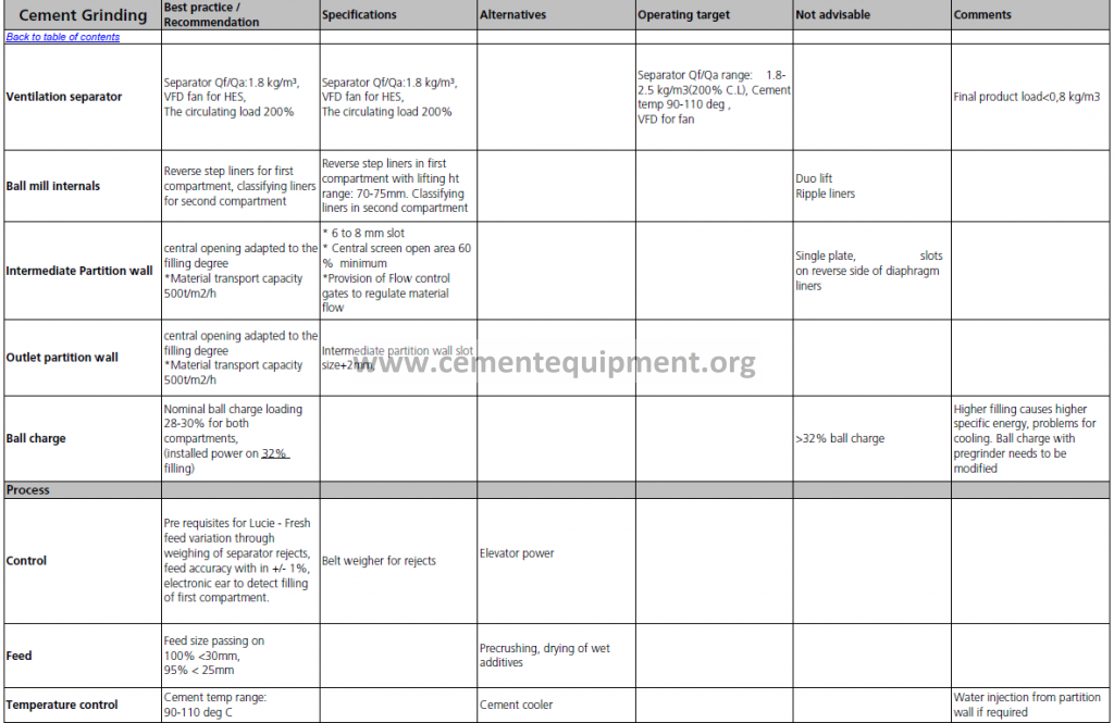
| Ventilation separator | Separator Qf/Qa:1.8 kg/m³, VFD fan for HES, The circulating load 200% |
Separator Qf/Qa:1.8 kg/m³, VFD fan for HES, The circulating load 200% |
Separator Qf/Qa range: 1.8- 2.5 kg/m3(200% C.L), Cement temp 90-110 deg , VFD for fan |
Final product load<0,8 kg/m3 | |||||||||||||||||||||
| Ball mill internals | Reverse step liners for first compartment, classifying liners for second compartment | Reverse step liners in first compartment with lifting ht range: 70-75mm. Classifying liners in second compartment | Duo lift Ripple liners | ||||||||||||||||||||||
| Intermediate Partition wall | central opening adapted to the filling degree *Material transport capacity 500t/m2/h |
* 6 to 8 mm slot * Central screen open area 60 % minimum *Provision of Flow control gates to regulate material flow |
Single plate, slots on reverse side of diaphragm liners | ||||||||||||||||||||||
| Outlet partition wall | central opening adapted to the filling degree *Material transport capacity 500t/m2/h |
Intermediate partition wall slot size+2mm, | |||||||||||||||||||||||
| Ball charge | Nominal ball charge loading 28-30% for both compartments, (installed power on 32% filling) |
>32% ball charge | Higher filling causes higher specific energy, problems for cooling. Ball charge with pregrinder needs to be modified | ||||||||||||||||||||||
| Process | |||||||||||||||||||||||||
| Control | Pre requisites for Lucie – Fresh feed variation through weighing of separator rejects, feed accuracy with in +/- 1%, electronic ear to detect filling of first compartment. | Belt weigher for rejects | Elevator power | ||||||||||||||||||||||
| Feed | Feed size passing on 100% <30mm, 95% < 25mm |
Precrushing, drying of wet additives | |||||||||||||||||||||||
| Temperature control | Cement temp range: 90-110 deg C | Cement cooler | Water injection from partition wall if required | ||||||||||||||||||||||
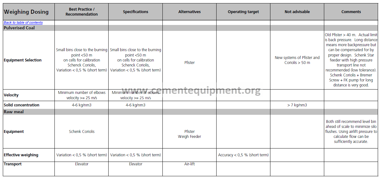
| Weighing Dosing | Best Practice / Recommendation | Specifications | Alternatives | Operating target | Not advisable | Comments | |||||||||||||||||||
| Pulverised Coal | |||||||||||||||||||||||||
| Equipment Selection | Small bins close to the burning point <50 m on cells for calibration Schenck Coriolis, Variation < 0,5 % (short term) |
Small bins close to the burning point <50 m on cells for calibration Schenck Coriolis, Variation < 0,5 % (short term) |
Pfister | New systems of Pfister and Coriolis > 50 m | Old Pfister > 40 m. Actual limit is back pressure. Long distance means more backpressure but can be compensated for by proper design. Schenk Star feeder with high pressure transport line not recommended (low tolerance). Schenk Coriolis + Bremer Screw + FK pump for long distance is very good. |
||||||||||||||||||||
| Velocity | Minimum number of elbows velocity >= 25 m/s | Minimum number of elbows velocity >= 25 m/s | |||||||||||||||||||||||
| Solid concentration | 4-6 kg/nm3 | 4-6 kg/nm3 | > 7 kg/nm3 | ||||||||||||||||||||||
| Raw meal | |||||||||||||||||||||||||
| Equipment | Schenk Coriolis | Pfister Weigh Feeder | Both still recommend level bin ahead of scale to minimize silo flushes. Using airlift pressure to calculate flow can be sufficiently accurate. | ||||||||||||||||||||||
| Effective weighing | Variation < 0,5 % (short term) | Variation < 0,5 % (short term) | Accuracy < 0,5 % (short term) | ||||||||||||||||||||||
| Transport | Elevator | Elevator | Air-lift |
|
|||||||||||||||||||||
