Contents
Roller Adjustment and Skew Identification of Mechanical Problems & Symptoms
Skew, more than any other mechanical adjustment, is the least understood, the most misused, and is often the most troublesome mechanical issue with a kiln.
DEFINITION: Skew is the position of the roller axis with respect to turning axis of the shell. If they are parallel then the roller is said to have zero skew or be neutral. Zero skew means no axial thrust is created. If the roller is not parallel then it is said to be skewed or “cut” and does create an axial thrust that pushes the kiln either uphill or downhill. Because kiln shells are not truly straight its rotating axis at the rollers is not constant. Zero skew cannot be set with rollers that have a fixed base. This is only possible if the roller support base is allowed to articulate to follow the shell/tire wobble.
Skew is created with a very small (0.004 to 0.040 inches, 0.1 to 1.0 mm) pivoting adjustment and only changes the parallel relationship of the roller to the longitudinal axis of the rotating shell. It does not affect (to any significant degree) the position of the shell either in plan or elevation views. In other words the roller is pivoted but the shell is not significantly raised or moved laterally.
This simple, but important concept must be understood completely before correct roller adjustments can be made. Thrust control by skewing may be the single most important adjustment which influences the optimum mechanical operation of the unit.

What is Skew?
Skew is a description of the position of the roller axis with respect to the rotating drum axis. If these axis are parallel the roller is neutral or has zero skew. If they are not parallel then the roller is said to be “cut” or skewed either correctly by pushing the drum uphill or incorrectly when pushing the drum downhill. The amount of skew is typically 0.005 to 0.040 inches (0.1 to 1 mm) for rollers in good condition of any size.
Why Skew?
Since the drum is set on a slope, gravity pulls it downhill. Therefore something must control the axial drum position. Typically this is the job of the thrust rollers. But the skew of the carrying rollers can also counteract this gravitational pull. Often rotating equipment is economically built with light thrust rollers that need help from the carrying roller’s skew to keep the drum from pushing downhill too hard.
Why is Proper Thrust Important?
Any amount of skew acts to deteriorate and tear up the rolling surface. If the operation of the unit requires some carrying roller skewing to limit the load on the thrust rollers then the skewing must be set to the minimum in order to save wear and tear as much as possible. Skewing is really a compromise whereby some of the long term running life is sacrificed to save the capital cost of more expensive thrust rollers.
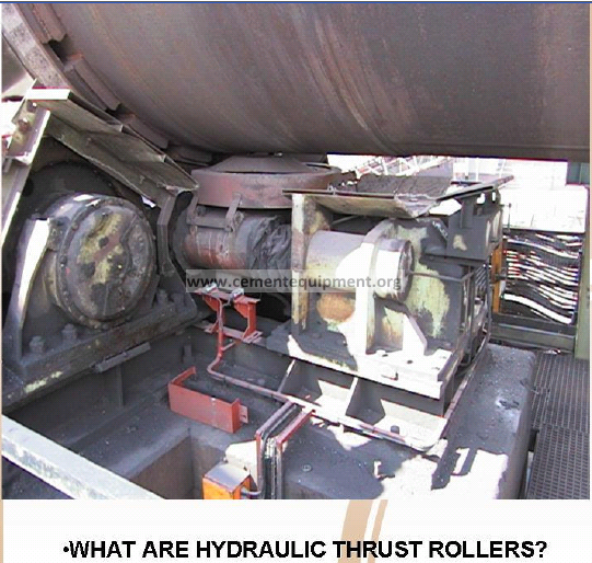 What are Hydraulic Thrust Rollers?
Hydraulic thrust rollers move the entire kiln axially about ±1 inch (± 25mm). They run on rails and are powered by hydraulic rams. They are designed to carry 100% of the thrust load of the kiln allowing the carrying rollers to be adjusted to neutral skew. This minimizes roller-tire wear considerably and to distribute the remaining wear across the running faces the mechanism is adjusted to cycle one stroke every 12 to 24 hours. This “adjustment” naturally also involves setting the rollers. For actual times please refer to the OEM’s recommendation.
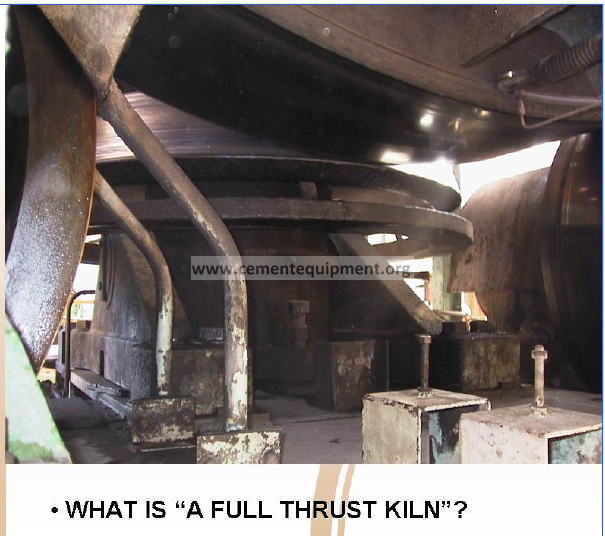
A “full thrust kiln” is simply one fitted with static thrust rollers that are large enough to fully support the kiln with the carrying rollers neutral. Sometimes with larger and longer kilns there are thrust roller assemblies on two or even more piers. There are kilns that have been built with as many as twelve (12) sets of support rollers.
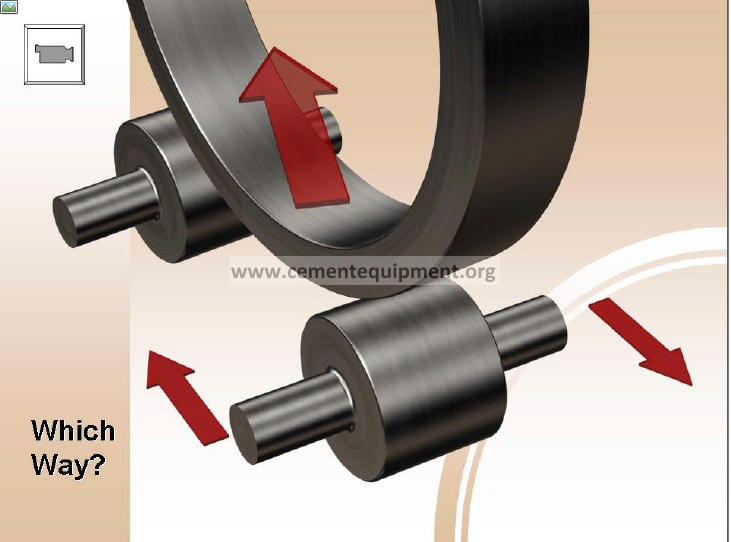
Which Way?
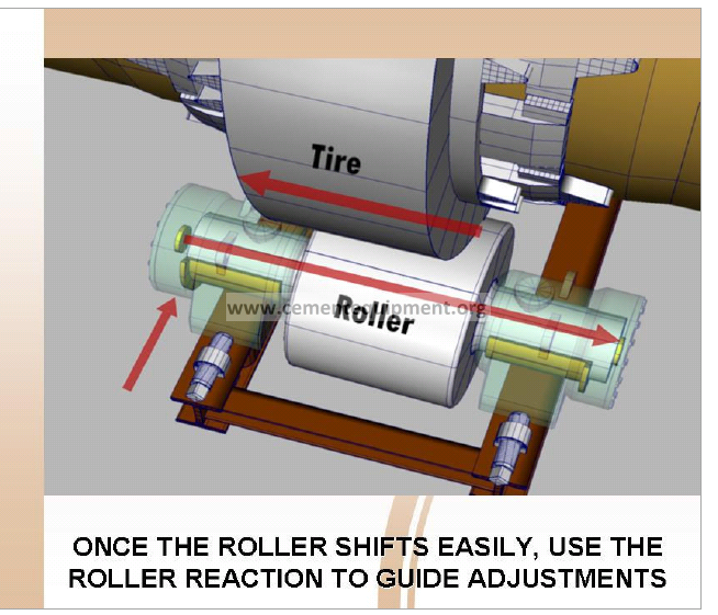
Understanding which way to position/reposition a roller and understanding the subsequent action and reaction of an adjustment is essential in gaining control of the mechanical operation.
Stand on the down- turning side of the drum.
Simply steer the roller in the direction the tire should be moved.
If the roller is steered to move the tire to the right the reaction is for the roller to move left.
If the roller is steered to move the tire left the reaction is that roller moves right.
It’s a case of simple action – reaction. Newton once postulated “For every action there is an equal and opposite reaction”. Pushing the tire one way causes the reaction of the roller to drive itself the other way.
The same holds true for the roller on the opposite side. Essentially the rollers should be always be kept parallel.
There is no logical sense or purpose to have the rollers “toed in”. Toed in rollers create unnecessary wear for no benefit whatsoever.
The animation provided on the CD which accompanies this book shows how the tire can be directed either right or left.
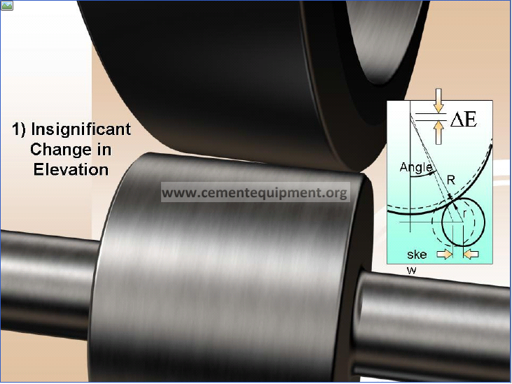
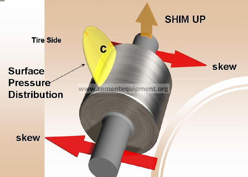
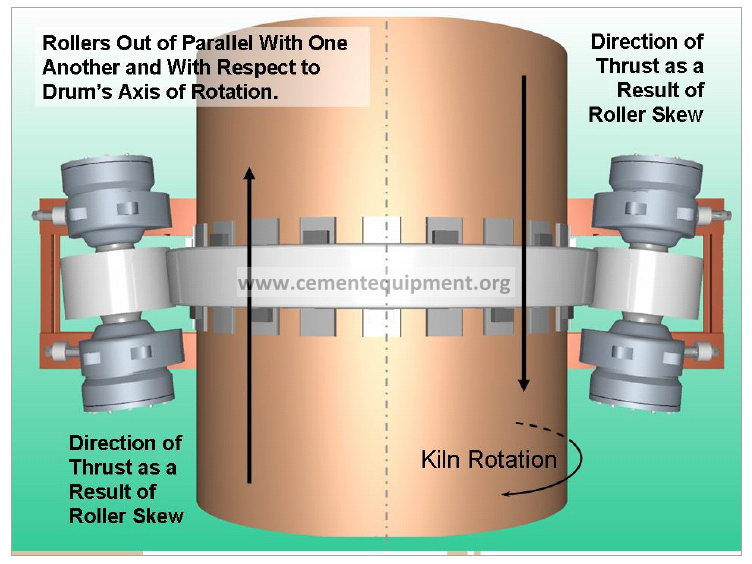
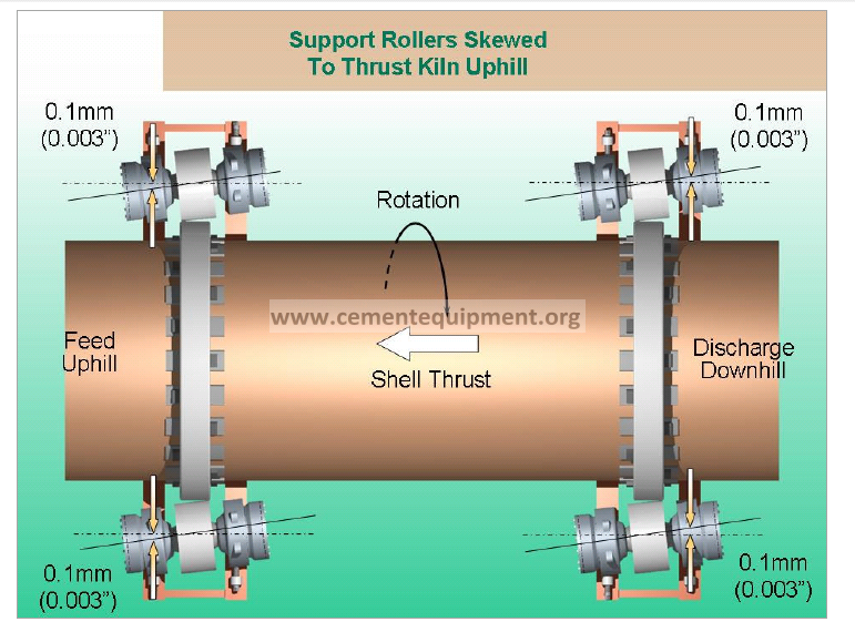
When the rollers are skewed, three things happen.
DE is then calculated to be 0.14mm (0.006”). The ratio is about 2:1 for easy reference. This ratio will not change enough to make a difference for any size kiln, cooler or dryer etc.
Although the skew is significant at 0.25mm, the change in alignment elevation, DE is not.
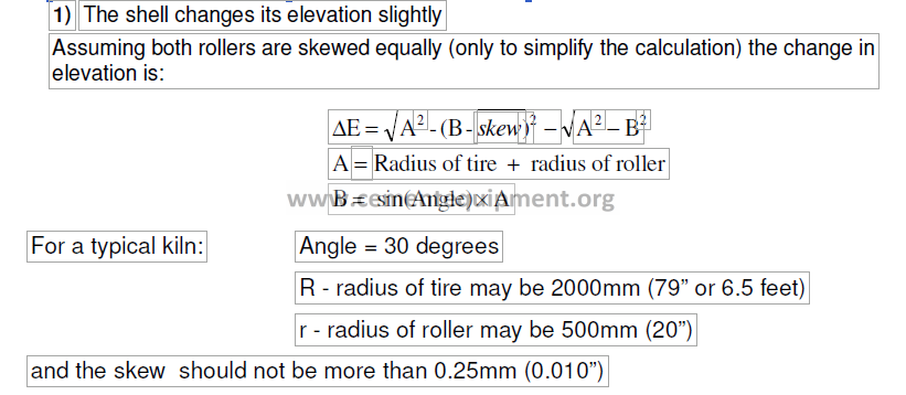
2)The line of contact between the roller and the tire changes. The line of contact is not really a line. It is an area defined by
the length of contact between the roller and the tire in the axial direction.
the width of contact which varies according to:
- roller diameter
- tire diameter
- hardness of the material
- roller slope matching the tire slope
- amount of skew
It is most desirable to have the area of contact as rectangular as possible. e.g… view (a). When skewing is required, which is the case for many units by design, then clearly the minimum amount of skew to just balance the down thrust of the shell, should be sought. The skewing should be shared equally by all the rollers. For illustration purposes diagram (b) shows excessive skewing, so much so that only half the roller face is in contact. Since the load this roller carries has not changed, the stresses in this reduced area must necessarily be higher. Visually the stress volume of the yellow shape at “a” must equal that of “b”.
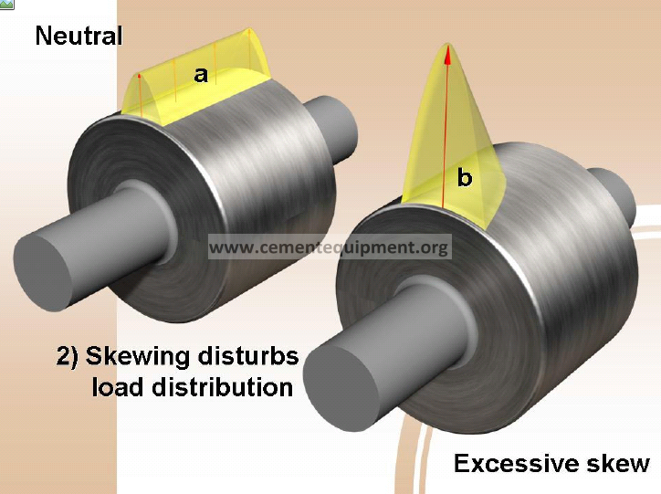
We can see therefore that excessive skewing decreases the contact area and increases the unit load, and stress, in that area. The contact area behaves similarly to a car tire in contact with the road. The contact area actually flattens out and the material in the flat area deforms. When this deformation exceeds the elastic limits of the material, it fails.
Skewing causes edge loading as seen in “b”. This can be catastrophic if the skewing is excessive. The symptoms would include mushrooming, edge cracks in the rim and ultimately large pieces coming out of the loaded edge of the roller. Since some skewing is required in most cases, changing the roller slope by shimming is beneficial. Only bearing housings that have self aligning bearing sleeves or spherical roller bearings are easily adjusted in this way. Bearing housings with fixed sleeve bearings can be shimmed using tapered shims but this is a more complex procedure. Shimming as a compensation for skew is often restricted to larger units. When it is required it will be stated in the kiln manufacturer’s documentation.
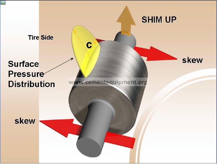
When the roller slope is adjusted for skew the load carried by the roller is distributed as shown in “c”. The peak stress is moved back to the center of the roller, the stress reduces towards the edges and is symmetrically distributed. This is a much better distribution pattern and makes the effort to do this worth while.
On the upturning side of the kiln shell the downhill bearing is shimmed and on the downturning side the uphill bearing is shimmed. The shim thickness is about 0.6 times the amount of skew.
With the highest load centered on the roller we see why convex/concave wear is a natural result.
Slipping / skidding
As long as the the tire and rollers are free to shift they do so until the roller shaft reaches and seats on a thrust bearing. Similarly the tire will shift until it bumps up against a thrust roller.
When neither the ring or the roller can shift, the thrust load is relieved by slippage. Therefore, with skewed rollers we no longer have pure rolling action. Slippage is another effect that causes problems. It tears the rolling surfaces. An overly skewed support roller can generate more thrust than the thrust bearing can handle. The oil film in the bearings becomes too thin, metal to metal contact occurs, the surfaces heat up which reduces the oil viscosity further, and the bearing fails. Once the thrust bearing fails the heat generated is usually enough to fail the support bearing as well. When support rollers are fitted with spherical roller bearings the situation is more critical since the thrust load and the support load both act on the one bearing simultaneously. These will tend to fail more frequently than journal bearings with thrust rings or thrust buttons.
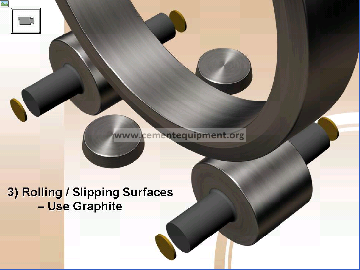
Since a skewed roller no longer runs against the tire with a pure rolling action, but induces some slippage, lubrication of the outside diameter with dry graphite is highly desirable, and helps preserve the surfaces. Oil lubrication on the rolling surface should be avoided as it can promote spalling.
Once again we have good cause to avoid skewing when possible and to limit it to a minimum when it is required.
THE HAND RULE
Until you get used to visualizing the actual motions of the roller and tire, this “hand rule” may help sort things out.
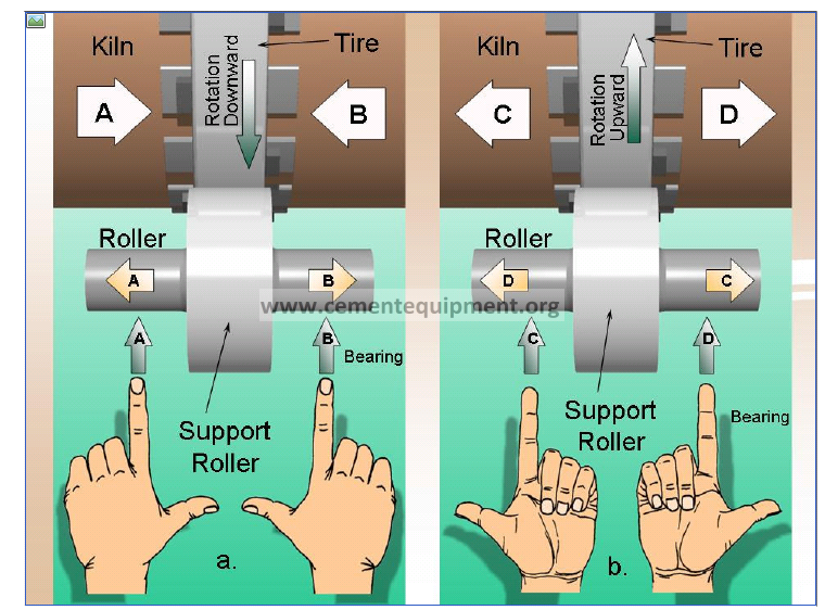
The palms: Stand and face the tire as it moves in front of you. If the tire surface is moving up – hold your hands out, palms up. If the tire is moving down – hold out your hands, palms down.
Fingers: Curl the fingers into your palm. They point into the direction the top of the roller is moving. When palms are up the fingers curl up towards you which is the way the top of the roller is moving. When palms are down they curl down and away from you, again the way the top of the roller is moving.
Index finger: Points to the direction which the bearing is to be moved.
Thumb: Points to the direction the shell will move as a result. For (a) pushing the left roller in will cause the shell to move to the right, and so on.
Remember, the thumb points into the direction the shell will move. The roller reacts by shifting itself in the opposite direction of the shell.
ALWAYS USE AN ADJUSTMENT LOG BOOK.
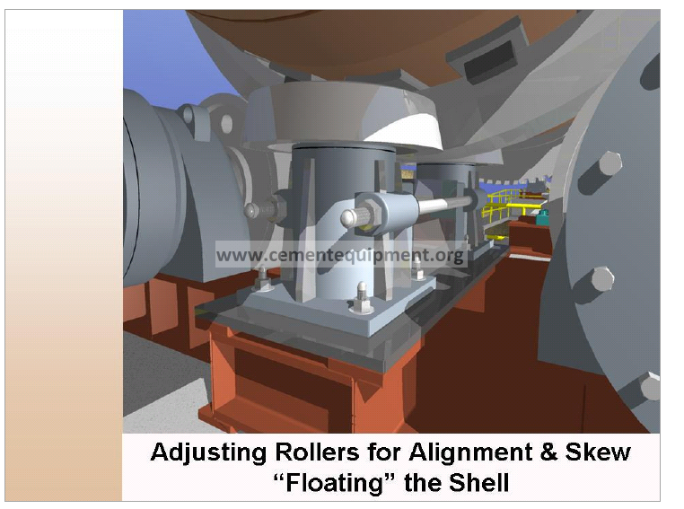
PUTTING IT ALL TOGETHER
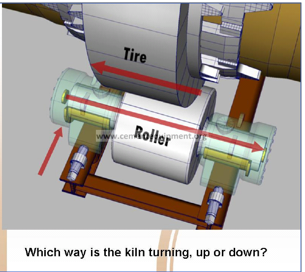
By looking at a full roller support station assembly we should easily be able to predict the reaction of the shell to a skewing adjustment of the rollers.
Given the information shown in this illustration, which way is this kiln turning, up or down?
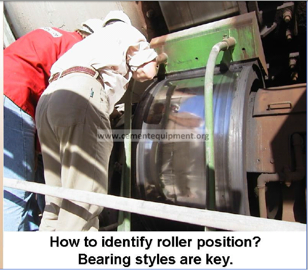
Understanding the mechanical arrangement of the roller bearing housing is key to determining roller position. By roller position we mean its axial position either downhill or uphill. Since it is impossible to see skew we use the roller’s axial position to show us which way it is skewed.
If skewed correctly the roller should always be sitting downhill. If hydraulic thrust rollers are in use and/or a roller is neutral, its position may change from time to time. In such cases visual and tactile inspection of the roller face will give us more information about the direction of skew if it is present. More on this later.
The following nomenclature for Bearing Styles is meaningful only within the confines of this presentation and is not recognized elsewhere.
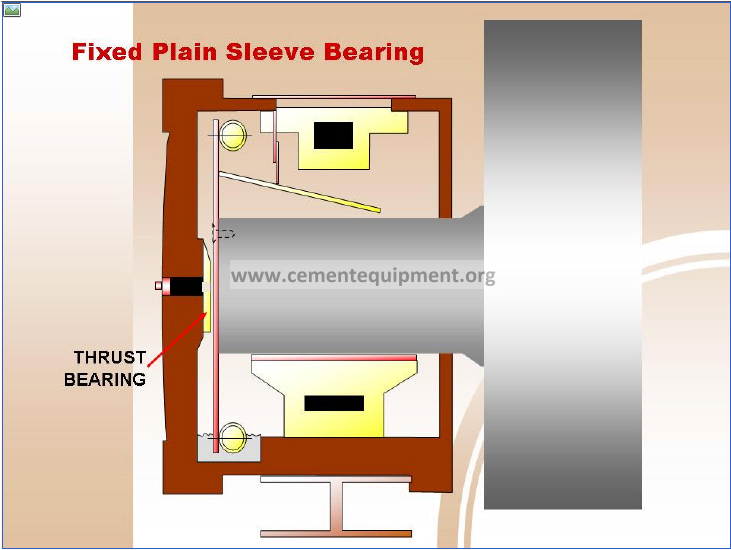
DETERMINE THE BEARING STYLE Type I.)
Fixed Plain Sleeve Bearing with Thrust Buttons on the End Caps.
CHECKING AND DOCUMENTING THRUST
Checking the thrust on a housing that has the thrust buttons in the end caps is pretty simple. Using a 3 or 4 LB. hammer, and lightly striking the end cap on or near the center, will produce one of two different tones. One is a hollow “bong”, or empty sound, which indicates that this end cap has no load on it. The other sound is a very solid, high “ping” like striking an anvil, indicating that the roller is loading up against this end cap. This style of roller is considered a “pusher”. When thrusted, the shaft will load up against one end cap and push the kiln in the opposite direction. For example, if the uphill end cap sounds hollow, and the downhill end cap sounds solid, the roller is positioned downhill and is pushing the unit uphill.
Remember to sound both end caps, even though the first one you strike may produce one of the distinct sounds mentioned above. If the roller is midway in the bearing this will cause both ends to sound hollow.
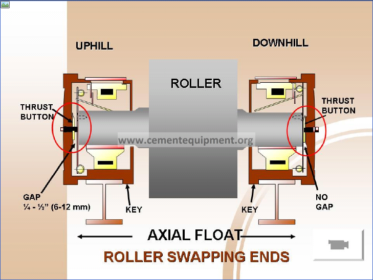
DETERMINING THRUST DIRECTION BY ROLLER POSITION (Type I Housing)
Both uphill and downhill bearing housings are keyed into the bases such that the space between the thrust buttons is ¼ – ½” or 6 – 12 mm larger than the length of the shaft. This allows the roller to have that much axial float. When the roller is skewed to drive the shell slightly uphill, its reaction is to slide downhill. The normal and expected position for all the rollers is to be in contact with the downhill thrust button.
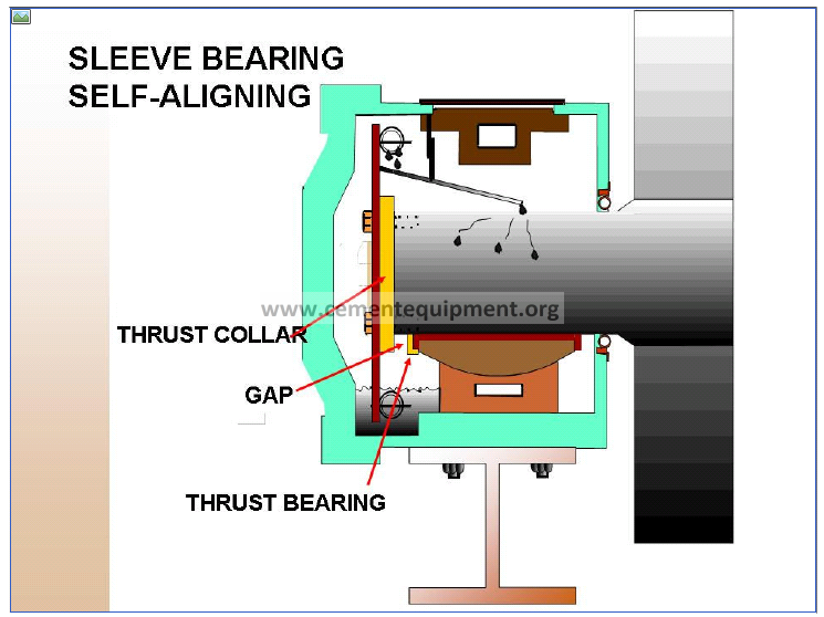
DETERMINE BEARING STYLE Type II.)
Sleeve Bearing, Self-Aligning with Thrust Collars on the Shaft
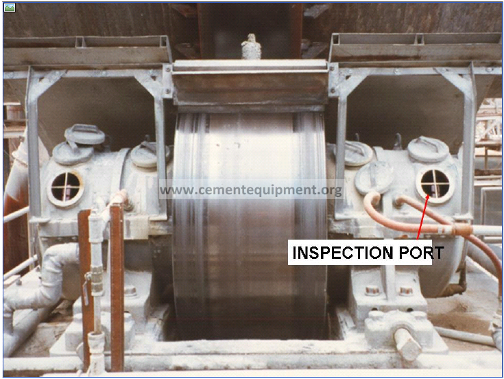
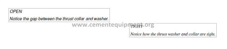
The thrust collars are located on the ends of the shaft or on the shoulder of the shaft near the roller. Visual inspection through the inspection ports of the housing allows us to locate the gap. This is the gap between the thrust collars and the thrust bearing.
With the thrust arrangement as shown above, the normal expectation is to have the gap on the downhill end of the shaft. This indicates the roller is positioned downhill and is pushing the shell uphill.
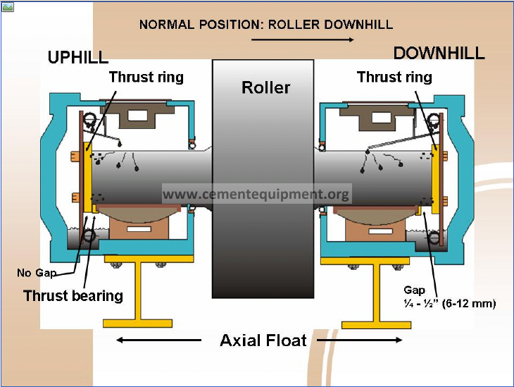
DETERMINING THRUST DIRECTION BY ROLLER POSITION (Type II Housing)
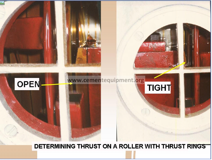
The normal and expected position of all the rollers, if slightly skewed to push the shell uphill, is to position itself downhill. With Type II style bearings we then expect to see no gap on the uphill side and a ¼ – ½” or 6 – 12 mm gap on the downhill side. Tapping the end covers on this style of bearing housing does not tell us anything.
Determining thrust on Type II style housings is a matter of removing the inspection ports and examining the position of the roller. When the ports are removed you will see where one thrust washer is tight by noticing that oil has been wiped clean from its surface. This can only be seen on the roller on the down turning side of the shell. The other should show a gap in which the oil runs freely over the thrust washer. This type of roller is considered a “puller”. This means that the shaft will move until it seats against the thrust collar.
DETERMINING BEARING STYLE Type III.)
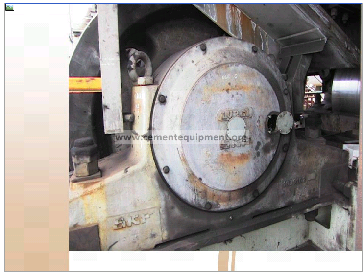
Spherical Roller Bearings (No separate thrust bearings)
This is the most difficult type of bearing to deal with for setting skew. The previous style of bearings are specifically designed to utilize the “action-reaction” phenomenon of skew by allowing room for a small amount of axial shift. That ¼ – ½” or 6 – 12 mm float is essential for setting skew correctly. With spherical roller bearings there is no accommodating float to show us skew direction. Spherical roller bearings are mostly installed on smaller faster-turning units. Faster turning means a proportionately higher thrust for any given skew. Unfortunately these bearings have a low tolerance for thrust load. Consequently we see a much higher failure rate with spherical roller bearings as compared to Type I and Type II bearings.
There are however a significant number of full sized kilns that also use spherical roller bearings as shown here. Making fine roller adjustments for a close determination of skew must first be done by very careful measurement. After that, long term observation of the surface condition is the final guide.
The biggest draw back in using spherical roller bearings for support rollers is that we cannot take advantage of literally seeing the roller move axially when it is adjusted through the neutral position. The sleeve bearing design commonly used in large kilns purposely allow about ¼ to ½ “ axial float so that the neutral position can be established by simple adjustment.
With spherical roller bearings careful measurement will get us very close, often within 10 to 20 thousandths of an inch with respect to neutral. After that we have to use visual and tactile observations to establish weather further fine adjustment is needed.
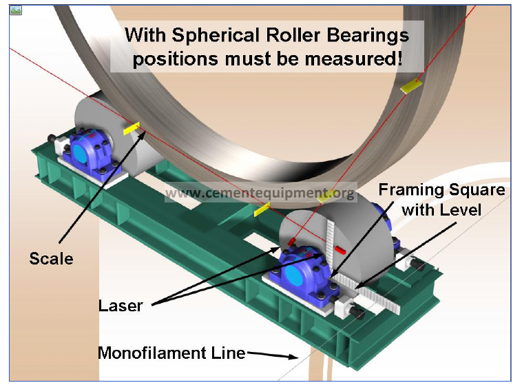
The safest method is to measure to the shafts using a framing square fitted with a torpedo level to a piano wire as described in the 2-pier alignment procedure. Better would be to make these measurements optically. That simply replaces the wire.
Laser equipped levels are now available with a magnetic base. These are quite handy to measure the roller position with respect to the tire using a small scale as shown. Point the laser in two directions as shown and repeat with three or four different kiln positions and at each side of the roller. The more measurements are made the more accurate the results will become.
All these procedures can only be safely done with the unit shut down.
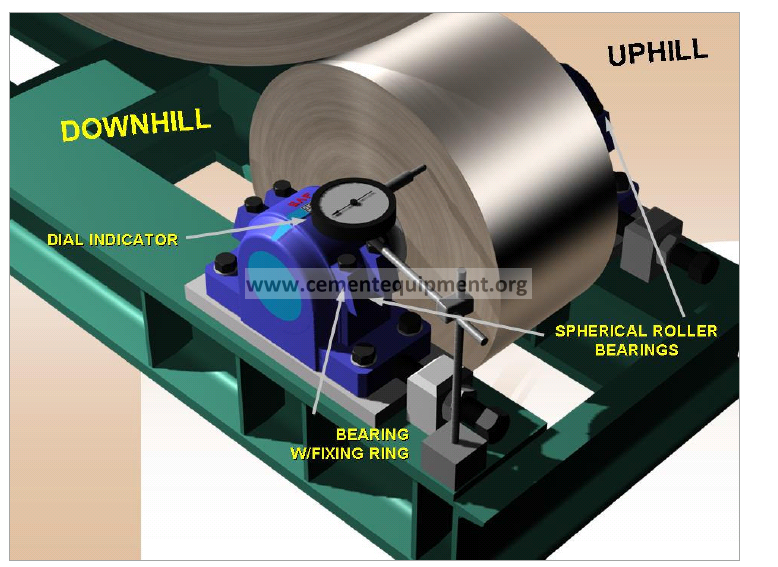
Spherical Roller Bearings (No separate thrust bearings)
This is the most difficult type of bearing to deal with for setting skew. In contrast, sleeve bearings are specifically designed to utilize the “action-reaction” phenomenon of skew by allowing room for a small amount of axial shift. This feature is not available with spherical roller bearings. These bearings also have a low tolerance for thrust load. Consequently proper and limited thrust adjustment is required.
By fixing a dial indicator as shown, thrust load may still be detected since there usually is some axial play in the bearing assembly. Any thrust load will tend to load the bearing slightly. Since the tire will never run true axially this wobble is seen with each turn of the drum by a constantly swinging indicator reading. The greater the thrust load, the greater the amount of movement. By making small roller adjustments, if that’s possible with the unit running, it is usually possible to detect whether the roller is favoring a load uphill or downhill. The roller should never be adjusted to push the drum downhill. A properly adjusted roller will thrust the unit lightly uphill necessitating that the roller will be pushed slightly downhill.
Small adjustments, a few thousandths of an inch, if they make the roller axis cross the neutral point, will show up on the dial indicator when positioned as illustrated.
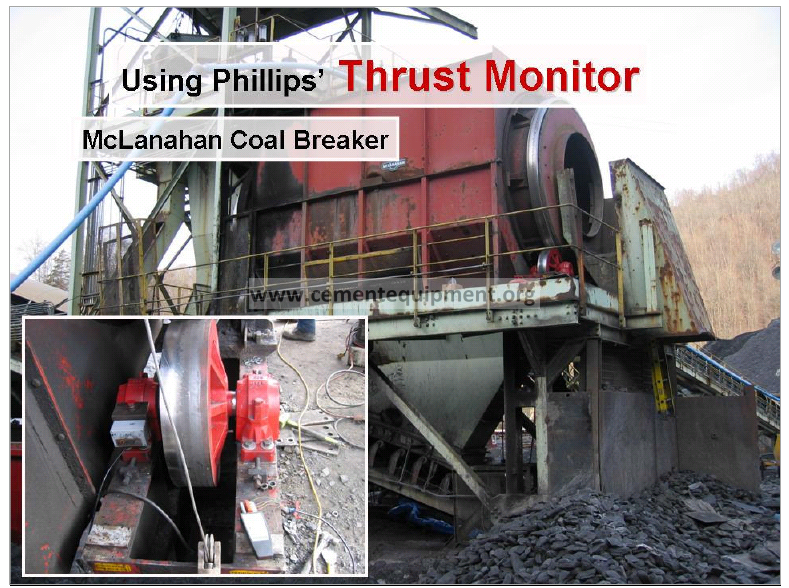
Phillips Kiln Services has solved the problem of fine tuning roller skew whenever spherical roller bearings are used with the introduction of the Thrust Monitor.
A sensor is attached to one of the two bearings supporting the roller shaft. This sensor will send signals indicating the exact amount and direction of any thrust developed as a result of rotation. The Thrust Monitor does require considerable preparation to function properly. The tires should be freshly ground flat and be free of any type of lubricant. The rollers should also be new or freshly ground and be free of lubricant as well. A full alignment must then be done in the conventional manner with particular emphasis on attaining the correct roller slopes by careful shimming if necessary. The calibration procedure of the Thrust Monitor is then most conveniently done as part of the alignment/shimming work since lifting the drum free of the roller is a necessary step to define the condition of zero skew.
The sensors must be mounted on the bearing with the fixing ring, which is usually mounted in the downhill bearing.
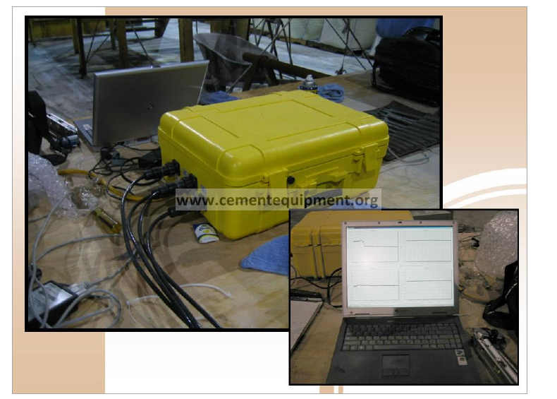
As there are at least 4 rollers there will be at least 4 sensors, one for each roller. These are cabled to a central control unit. A computer is connected to the control unit and the thrust levels can then be observed and monitored on the computer screen numerically or graphically.
For permanent installations the sensor signals are carried via Ethernet to a web port and so the data can be monitored remotely.
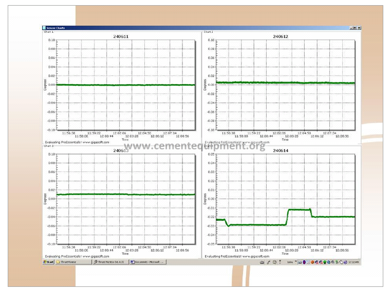
Thrust is seen as a simple line graph. With the start of rotation, any amount of skew on a roller will immediately cause the line graph to increase if the resultant thrust is pushing the drum uphill or will decrease or fall below zero if the thrust is driving the drum downhill. The magnitude indicates the strength of the thrust force.
The direction of thrust and relative magnitude is seen at a glance. Changes in thrust due to minute adjustments on a roller (#4 in the case above) are immediately apparent. Adjustments of less than 0.005” [0.1mm] are easy to see.
The Thrust Monitor is particularly well suited to rotating drums supported by rollers fitted with spherical roller bearings because it is the only way that thrust can be measured on such assemblies.
However axial thrust forces are developed by a skewed roller no matter which type of bearing is employed so the Thrust Monitor can be employed in all cases where thrust measurement is of interest.
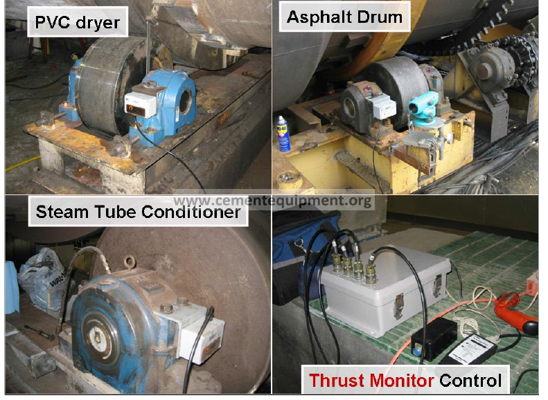
There is a great variety of process equipment who’s mechanical integrity can be significantly enhanced by maintaining minimum and balanced thrust on the supporting rollers.
In almost all cases where heavy metal flow on the rolling surfaces occurs or where bearings fail or where thrust rollers fail, improperly skewed or heavily skewed rollers are the cause.
Improper skew very often results from roller adjustments made to improve face contact when the rollers are not on the correct slope. Anytime a roller is off its required slope, adjustment for improved face contact creates axial thrust. Stated another way; any time a roller is off slope, a neutrally set roller can never have full face contact.
This condition is by far the most common cause of mechanical problems with rollers.
Use of the thrust monitor will immediately identify this condition.
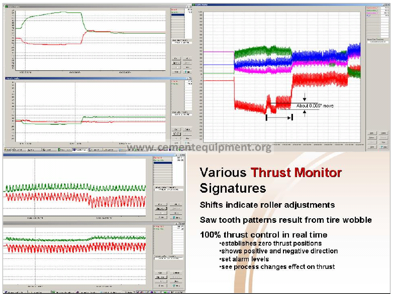
The illustration, upper right, shows the thrust monitor straight lines, indicating no rotation, coming in from the left. Since all the sensors were made active on one screen for easy comparison they were “zeroed” with an offset so that one did not hide the others. As soon as rotation commenced only the “blue” roller remained at zero thrust indicating it was neutrally skewed. Both the red and pink rollers dropped down from their “zero” position indicating they are skewed to push the drum downhill. This is obviously an unwanted situation. The green roller’s thrust went positive (higher than its zero set point) indicating it is the only one pushing the drum uphill.
We then see the effects of making several 0.005” moves on the red roller, an effort to neutralize it. Even though only moves were made on the red roller we see the ripple effect on the others. Towards the end of the chart a move was made on the green roller causing all the others to go up.
The raggedness of the signal is simply the “mechanical noise” of rotation. Rotation noise is cyclical going up and down with each turn of the drum. If we expand the time scale as shown in the lower left illustration we can see the saw tooth like pattern most of which is caused by tire wobble. Tires never run perfectly true because of the way this type of equipment is fabricated. The resulting tire wobble drags the rollers in one direction for half a rotation and then in the opposite direction for the other half of the rotation.
In the upper left we can see just the thrust levels after the cyclical “noise” is filtered out.
A Visual Check of the Running Surface
Determining roller position, uphill or downhill is only the first step. We also want to know how much each roller is skewed. Lets look at the surface of the roller. A well adjusted roller, one with a minimum amount of skew, close to neutral, will look very polished. Its surface will be mirror like, almost chrome plated in appearance and be very reflective. A poorly adjusted roller with excessive skew will appear dull and gray by comparison. In the extreme it will be very rough and have tiny flakes of material coming off its surface.
Then the Wipe Test
Take a cotton rag, wipe across the face of the roller. First wipe from the discharge end towards the feed end. Then wipe the opposite way. On the roller with a dull surface there will be a distinct roughness in one direction, the fibers of the cloth almost seem to catch on the grain. The other direction will seem much smoother and the cloth will not hang up on the grain. On a shiny roller this difference will be imperceptible. By wiping all the rollers it will be easy to judge which is the roughest and which are the smoothest.
Any detectable roughness should be in the direction from discharge to feed end. That means the roller is pushing the shell up-hill. Roughness feed-end to discharge-end means the roller is reversed skew, pushing the kiln down-hill.
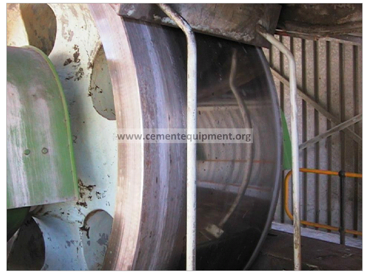
What does it mean to “float the shell”?
When the shell rotates such that the downhill thrust roller is only engaged for a partial revolution and all the rollers are correctly skewed, then we can say the shell is floating. The thrust tire will always have a slight amount of wobble. While the thrust roller is in contact this causes the kiln to be pushed uphill for part of the rotation. As the wobble then moves away from contact with the thrust roller, the kiln moves gently downhill for that part of the rotation. The cycle then repeats.
What is “correctly skewed”?
Each roller is pushing the kiln uphill and with a minimum amount of thrust. This minimum is defined by the condition above. The combined thrust of all the rollers does not quite match the downward push of the kiln. In this way the kiln will slowly and gently move down but then be nudged back up by the wobbling thrust tire.
“Floating” the shell.
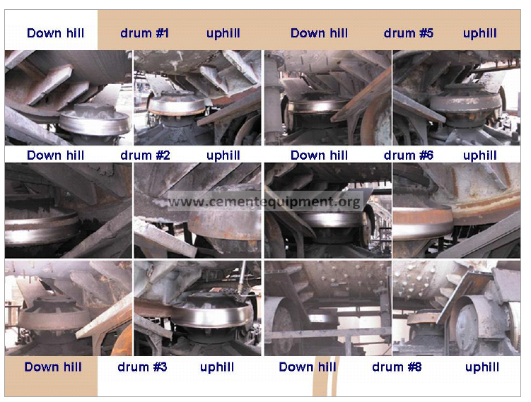
When the unit is said to be “floating” it means that the the natural pull of gravity on the unit down the slope is exactly balanced by the combine force of the skewed rollers pushing the shell up. The forces from each of the rollers should be equal. This floating condition is of course transient since the thrust from skewing varies according to shell speed and the load in it. This means that occasionally the upper thrust roller will be rotating but more often we expect the lower one to be rotating. Looking at the relative shininess of the upper and lower thrust rollers tells us much of what is going on.
Look at the six units above. Unit #3 has a rusted lower thrust roller. Obviously the rollers are skewed too aggressively. At the other extreme is two, five, and eight where the upper thrust rollers never seem to see contact.
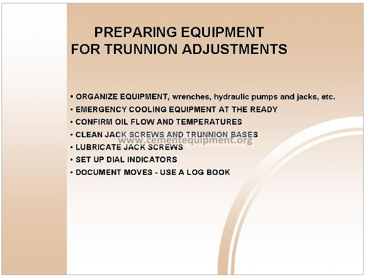
General housekeeping is important.
Attitudes and the level of respect given the equipment is largely dictated by general housekeeping. The biggest problem is usually oil or water mixed in with product that contaminates (sometimes buries) part of the base assemblies. If pier tops are covered by spent oil or buried in spilled product the expectation of good maintenance is largely undermined.
Clean up as required, prepare and assemble all the necessary tools to do the work.
A very important step is to assure there is a meaningful way to measure bearing oil temperature. If a problem should arise chances are that the first indication will be a rapid rise in bearing oil temperature. Monitoring all the sump temperatures through out the process is essential.

If there is a history of hot bearings or if problems are anticipated for whatever reasons be prepared to deal with the situation of hot bearings. For units with sleeve bearings If a problem arises as a result of roller adjustments hot bearings are usually the first in the list. Be prepared.
The problem is either excessive thrust where the thrust bearing heats up or more usual there are grooves in the bearing shaft and brass sleeve which prevent smooth axial float.
If there is excessive thrust graphite powder can be applied liberally to the roller face. This will relieve all thrust and may allow the trunnion to cool. The graphite must be continuously applied until counteracted moves can be made, and the trunnion can be put into a position where it will run cool.
Do not blow air into the housing through the inspection port. This may cause an explosion.
It is not recommended that water be run directly on the trunnion face. Make sure water is flowing freely through the cooling jackets.

Usually the best method of cooling is to use a water to oil heat exchanger or oil cooler. These are readily available commercial units. The suction side of the pump is connected to the oil drain on the trunnion. The oil is then dispensed onto the top of the trunnion shaft through the inspection port. It is also recommended to add an oil filter. Caution must be used to keep the filter as free-flowing as possible.
If a bearing is known to be a problem synthetic oil should be used before any moves are attempted. Synthetic oil retains its viscosity to 450°F [230 °C]. If a petroleum oil is being used be prepared for the possibility of having to change oil “on the fly” to a synthetic to sustain a high rise in temperature. Some synthetic oils are not compatible with petroleum oils. The changeover must be total without cross contamination. Continue flushing with synthetic until the change is complete.
If none of these methods bring the temperature under control, bearing failure is imminent. Prepare to slow and stop the kiln. A slowed kiln may allow the problem bearing to “seat-in”. However an overheated bearing is damaged and cannot repair itself by continued operation. Even if the temperature is brought under control the situation can redevelop at any time. The sleeves and roller need to be change at first opportunity.
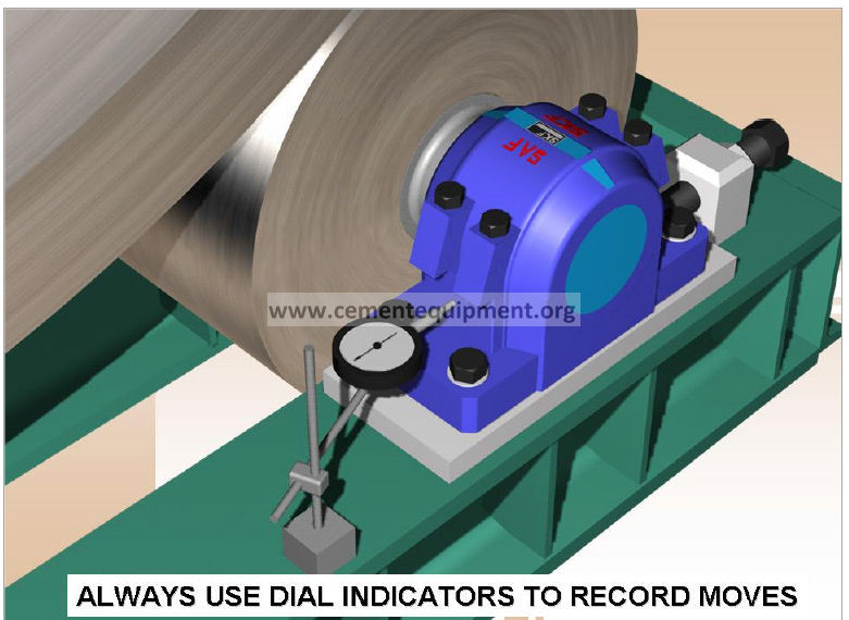
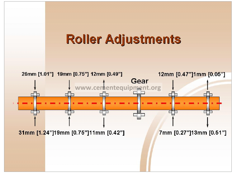
Moves can be properly recorded using a dial indicator, one for each bearing assembly, positioned at the backside of the bearing as shown. Often the magnetic bases for the dial indicators are inadequate to hold the indicator reliably over the course of an adjustment campaign. Weld brackets to the base and use clamps to hold the indicators for 100% reliability.
Adjustments using the “flats” of the adjustment screw is good enough for “ball park” adjustment but must never be relied on for recording the actual moves made. The bearing housing may take some time to seat in. Leave indicators in place for as long as 24 hours after the last adjustment, before recording the final bearing position.
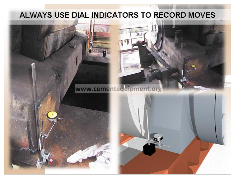
Moves can be properly measured using dial indicators, one for each bearing assembly. Often the magnetic bases for the dial indicators are inadequate to hold the indicator reliably over the course of an adjustment campaign. Weld brackets to the base and use clamps to hold the indicators for 100% reliability.
Adjustments using the “flats” of the adjustment screw is good enough for “ball park” adjustment but must never be relied on for recording the actual moves made. The bearing housing may take some time to seat in. Leave indicators in place for as long as 24 hours after the last adjustment, before recording the final bearing position.
From our previous inspection we have catalogued roller positions, surface conditions, thrust direction and what problem bearings (if any) exist. From this we can derive the most offending roller to the least, and sequence our adjustment campaign accordingly.
Suppose we were required to do more than set the rollers to their correct and minimum thrust. Suppose it was required to move them for alignment and skew as well. Say our first roller needs a 15 mm (0.6)”) move towards the center line of the unit in order to correct for alignment. This would then be an alignment adjustment. We will use the roller reaction to guide our work.
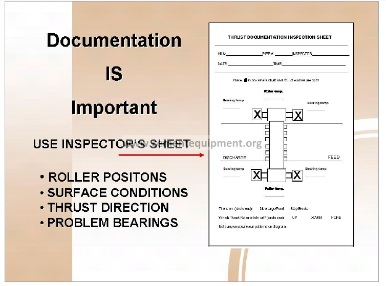
Documentation is important.
Only one person should be given authority to have moves made. He should provide written instructions as to which bearing should be moved and in what direction. Personnel making the moves should record, date and sign a record of their work. Inspection sheet as shown here for example is an efficient way to do this. These sheets should then be kept in a log book. A running history of roller adjustments is necessary to maintain control of the mechanical condition of the kiln.
If multiple moves on one roller are anticipated this sheet needs to be accompanied by a table on which moves, times and temperatures can be listed.
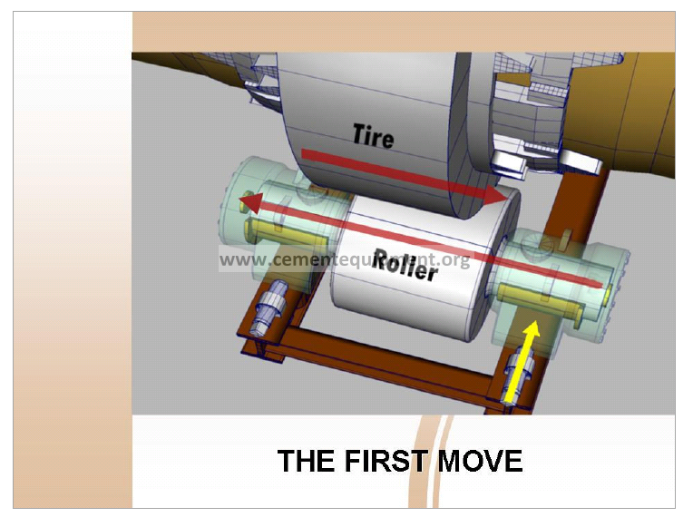
The First Move:
Once preparations are complete the first task is to record the temperatures on all bearing at all piers. An adjustment on one roller changes the overall thrust on the kiln and can cause it to shift with the potential of causing a hot bearing on another pier. Recording all bearing temperatures frequently throughout this process is required.
The first move would be a small one of about 0.5mm (0.020”) in one bearing. The bearing first moved would be the one which would bring the roller closer to neutral. Wait about 20 minutes until the roller has had a chance to shift. This is also enough time to record all temperatures again. Trouble can be identified by a temperature rise anywhere, not just in the bearing being moved. Assuming that the shaft journals and bearings are in normal condition and no temperature rise was encountered, these steps would be repeated as necessary until the roller shifts position. The roller’s shifting position indicates that the neutral point has been crossed. This is the most critical aspect of the whole procedure: to get the roller to shift position without any significant temperature rise in any of the bearings.
The “Cross-Over”
Once it is seen that the roller shifts easily without a temperature rise, then the size of the moves can be increased to say 2mm (0.80”) per bearing. The sequence of the moves should alternate from one bearing to the other with the shaft sliding across with each move. Waiting 20 minutes between moves is also unnecessary as long as the shaft shifts easily with each move. The work can continue smartly providing there are no other mitigating circumstances like a bowed shell, or a rise of oil temperature anywhere etc. This continues until the average of the moves for both bearings reaches the desired total, 15 mm for this example. The final moves should be very small ones to leave the minimum amount of skew on the roller.
Even the largest rollers, and there are some as large as 10 feet (3050 mm) in diameter, will respond quickly to a 0.10mm (0.004”) skew adjustment.
Naturally all the work must be monitored with dial indicators and must be done with the unit in operation.
This procedure is used with units that have sleeved bearings. See “Two-Pier Alignment” for the procedure using spherical roller bearings and pillow blocks. The principle of roller reaction is always valid even though thrust direction is not seen by axial roller shift. Secondary techniques need to be used.
This is not desirable.
Toed-in rollers can balance each other, one pushing the tire down as hard as the other is pushing it up. If situation exists the shell may be “floating”. Floating means that the shell is balanced between thrust rollers. But it is not the desired situation. Left uncorrected there is unnecessary wear and tear on the whole support. Left for long periods of time the tires and rollers will wear into a cone shape.
How do you quickly identify if a roller is skewed?
Look at the surface. A roller with little or no skew will polish up to a mirror finish. If the surface is dull and gray and appears rough, then skew is present and probably excessive.
This is also not desirable
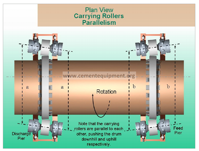
Rollers should be parallel to each other, set in the same direction on all piers. Often measuring between bearings or shafts, as “a” above, may reveal that they are parallel and not toed-in as in our previous example. Unless these measurements are tied into a common reference line, the above situation will not be identified.
Once again this situation could be present with the shell “floating”. Assuming from that observation alone that all is well, will lead to excessive wear and tear of all the support components. Careful inspection using the simple techniques already described will show this immediately.
Ideal Placement.
Unfortunately many designs require that support rollers be skewed. The thrust mechanisms of these designs are inadequate to support the entire downward thrust of the shell. This is especially true of large long rotary kilns. Since most of this type of rotary trunnion-supported equipment is installed on a slope, there is a natural component of force acting in the axial direction of the shell. If this force cannot be completely managed by the thrust mechanism(s) it is the skewing of the support rollers that must help out.
Skewing is a compromise. Skewing accelerates the wear and tear of the support mechanisms but then allows smaller, less costly thrust mechanisms to operate successfully. If skewing is insufficient the thrust mechanisms will fail prematurely. If skewing is excessive additional wear and tear of the support components takes place and the thrust mechanism can still fail. If rollers are skewed against each other, wear and tear takes place but the advantage supposedly gained by skewing is lost.
The maximum performance life of rotary equipment that requires skewing, can only be achieved by skewing correctly and keeping it to a minimum.
The amount of skew shown in the illustration may be sufficient for most installations
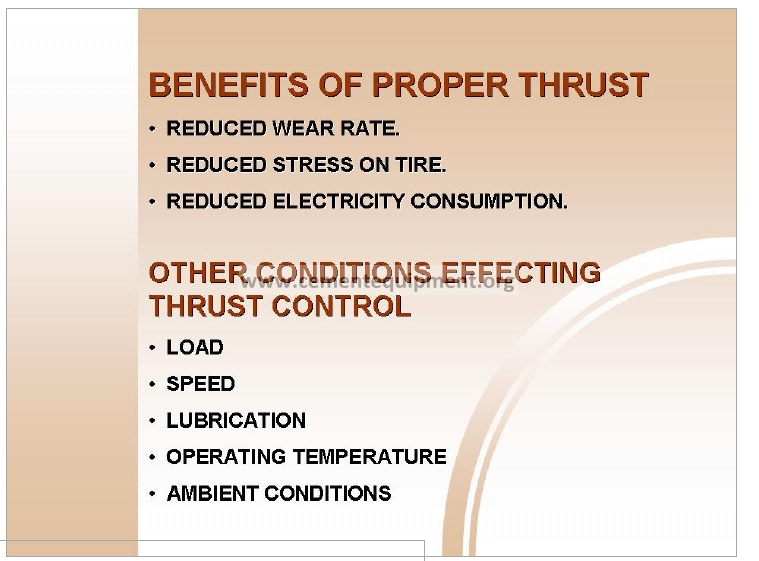
Proper skewing of the kiln can have many benefits
- Distributing the unit’s thrust load evenly, so one trunnion is not working any harder than another, reducing the wear rate.
- Distributing the load across the trunnion face equally among all of the rollers so that tire and trunnion wear is reduced.
- Reduction in stresses on the tire and its support components.
- Possible reduction in the unit’s main motor load. This will reduce electricity consumption and save money.
For a fixed amount of skew the resultant thrust force varies with: - Load. The heavier the shell, the harder it bears down on the rollers the more friction force develops. Lightly loaded the shell tends to sit downhill. The heavier its loaded the more it tends to run up hill.
- Speed. The amount of thrust developed is directly proportional to speed. A slow running shell will tend to stay downhill. The more it is sped up the more it will tend to climb uphill.
- Surface lubrication, temperature and ambient conditions, anything that will influence the grip or slipperiness of the rolling surfaces will effect the thrust developed.