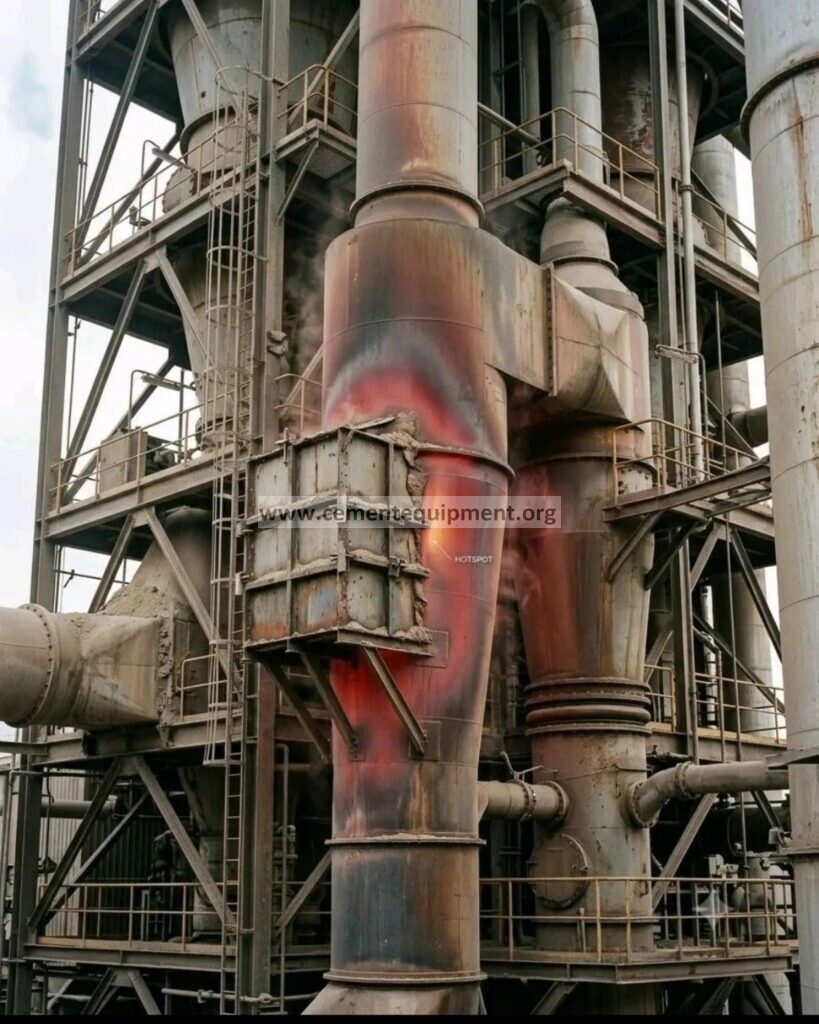
Technical field guide for kiln, refractory, process and reliability engineers. A rising shell temperature on a preheater cyclone or riser duct is first a warning that the local heat-transfer and containment system may no longer be performing as intended. It is not, by itself, proof of higher pressure drop, poor separation or lost kiln output. Those wider effects become plausible when the underlying damage also changes internal geometry, allows false air, creates build-up, compromises the dip tube or destabilizes gas–solid flow. Distinguishing an observed fact from a possible consequence is the key to an effective response.
Engineering and safety note: This guide is educational. Plant-specific equipment drawings, OEM limits, refractory specifications and an approved risk assessment take precedence. An actively overheating shell may require immediate controlled shutdown; do not use a website article as permission to continue operating.
The engineering answer in sixty seconds
When a refractory lining thins, cracks, detaches or erodes, less thermal resistance may remain between the hot process gases and the steel casing. The external shell can consequently run hotter. A localized hot spot can remain a localized refractory defect, or it can signal a more extensive fault that affects a cyclone’s internal contour and process performance. The latter depends on where the failure occurs, how much material has moved, whether deposits accumulate and whether associated internals have been damaged.
An externally fitted stone box—a field term used for a containment or insulating box around the affected area—may be considered as an engineered temporary measure at some plants. Its actual function and safe operating limits depend on its design, attachment, fill and the condition of the underlying steel. It does not replace missing internal refractory, recreate the original gas passage, repair a failed anchor or prove that the shell remains structurally adequate. An improvised box can even obscure a changing defect or introduce new loading and thermal-expansion problems.
The appropriate response combines three parallel questions: Is the shell safe? Why did the lining fail? Has process performance changed? These questions must be answered separately, then connected using reliable trends and inspections.
1. What makes a cyclone or riser duct different from ordinary hot ducting?
A suspension preheater transfers heat between rising combustion gases and falling raw meal across successive stages. Gas enters a cyclone tangentially and develops a swirling flow. Centrifugal action moves particles toward the wall, while the cleaned gas travels toward an outlet often controlled by an internal dip tube or vortex finder. Separated meal descends through the cone and discharge arrangement, generally feeding the next heat-exchange stage.
The geometry is functional, not merely structural. Cyclone inlet proportions, barrel and cone profiles, outlet diameter, dip-tube depth, transition shape and the arrangement of the gas and meal connections all influence pressure loss and separation. The riser duct is also part of the thermal and pneumatic system: flow velocity, distribution, meal suspension, fuel combustion location and deposit accumulation influence its performance.
Refractory linings protect carbon steel against process temperature, thermal cycling, abrasion and chemical attack. In selected locations they also determine the effective internal dimensions. A damaged lining therefore has two separate potential consequences: a change in local heat flow toward the shell, and a change in the internal passage seen by gas and solids.
Yet these consequences should never be conflated. A bare patch on the shell does not automatically increase cyclone pressure drop. Removing thickness from a lining could initially enlarge a cross-section. The more troublesome resistance changes can emerge from displaced lining, distorted metal, loose refractory, lodged deposits, damaged internals or changed solids loading. Direction and magnitude must be established from measurements.
2. What a hot spot means—and what it cannot prove
The simplest physical explanation is increased heat flux through a local wall. The original lining normally maintains a temperature gradient from the process-facing hot face toward the steel. If part of that barrier is lost, shell temperature may rise. Heat flux, however, also depends on gas temperature, local convection, remaining insulation, surface emissivity, outside convection and radiation, and ambient conditions. This is why an isolated thermal-camera reading should not be treated as a complete diagnosis.
A hot spot can indicate refractory erosion, explosive or thermal spalling, anchor failure, cracking, a void behind the lining, corrosion-related separation, direct flame or high-temperature gas impingement, or an abnormal process temperature. It may also coincide with a process upset such as excessive fuel feed, poor combustion mixing, chemical attack or abnormal meal distribution. The appearance on a thermal image alone cannot reliably discriminate among them.
Equally important, a shell can be in danger before any obvious red glow appears. Visible redness is affected by lighting, surface condition and temperature and must not be used as a safe operating criterion. The site needs calibrated instruments, repeatable measurement locations, trend information and a conservative response procedure.
Location changes the risk assessment
A hot region near a cyclone inlet, transition, structural attachment, expansion joint or dip-tube support may raise different concerns from a hot region on an unobstructed straight duct. Load paths, shell thickness, refractory support details, adjacent equipment and accessibility matter. A long horizontal band is not necessarily the same failure mechanism as a small isolated point, and a rapidly spreading hot region deserves more attention than a stable reading at an identical peak temperature.
Plot temperature, area and rate of change together. Record the exact elevation, angular position, shell surface condition and time. A rise over thirty minutes can carry a very different implication from a slowly changing pattern over several weeks—even if the latest measured value is the same.
3. Common refractory failure mechanisms
Abrasion and erosion. Fast-moving meal particles concentrate wear in bends, cyclone inlets, cones and areas with maldistributed flow. A localized weak spot can accelerate once the original smooth hot face deteriorates. Abrasion-resistant lining selection, correct installation thickness and aerodynamic design all matter.
Thermal cycling and spalling. Startups, shutdowns, feed interruptions and combustion disturbances impose expansion and contraction. Where the refractory material, anchors and substrate do not move compatibly, cracks may form and sections may detach. Inappropriate heat-up or dry-out can increase the risk after repairs.
Chemical attack. Alkalis, sulfur, chlorine and process-derived compounds may penetrate or react with certain refractory materials. Alternative-fuel conditions can change local chemical exposure. Correct material selection and investigation of process chemistry are as important as mechanical patching.
Anchor and installation defects. Inadequate anchor layout, welding, alloy selection, expansion allowance, mixing water, casting practice, curing, dry-out and vibration can all undermine service life. A repair that simply repeats the previous lining specification without understanding the failure mechanism risks recurring trouble.
Deposits, obstructions and abnormal flame patterns. Build-up can redirect a hot stream, create local impingement, or alter material distribution. In the riser or calciner region, fuel and tertiary-air distribution must be considered alongside refractory observations.
One practical lesson follows: the repair specification should be derived from the failure analysis. A familiar product name or the fact that a certain castable worked elsewhere is not enough evidence that it is correct for this location.
4. How refractory damage can become a process-efficiency problem
4.1 Pressure drop: a possible outcome, not an automatic diagnosis
The differential pressure across a cyclone represents the flow resistance between defined measurement locations. At otherwise comparable conditions, that resistance depends on the gas flow rate and density, effective passage geometry, swirl, inlet and outlet conditions, particle loading and deposit accumulation. A deteriorated lining may alter one or several of these variables. The common error is to compare raw millibar readings taken at unlike feed rates, gas temperatures or operating modes and then attribute the difference to the newest visible hot spot.
If a section of detached refractory restricts an inlet, or if disturbed gas–solid flow promotes deposits, measured resistance may rise. If a lining patch simply thins without obstructing anything, the measured pressure drop may not rise at all. In some arrangements the numerical change can be in the opposite direction. The diagnostic question is not “Did the temperature rise?” but “What changed in the flow path, and does the normalized pressure signature support that change?”
Record differential pressure at consistent taps, verify impulse lines, and note the kiln feed, raw-mill status, oxygen, gas temperature, fan speed, damper position and material chemistry. Pressure data from blocked taps or from unequal operating states can create a false failure narrative.
4.2 Cyclone separation and internal dust circulation
A cyclone must combine high enough centrifugal separation with tolerable pressure loss. The vortex finder and inlet configuration help establish the relevant vortex structure. A damaged dip tube, missing section of lining, significant geometric offset or accumulated deposits can upset this balance. More fines may bypass separation and continue with the gas to another stage or the dust collection system.
However, dust circulation is not measured by the shell thermometer. Examine meal temperature profiles, stage pressure behavior, dust loading and available sampling data. Compare material balances and any measured stage-to-stage carryover against a baseline. A changed bag-filter dust load can be informative, but it is not uniquely caused by cyclone refractory deterioration: feed fineness, gas volume, operating mode and separator condition also matter.
A published 2024 numerical study of an industrial-scale cement cyclone demonstrated that geometry adjustments could improve separation and reduce resistance together; the reported result belongs to that specific cyclone and is not a universal retrofit guarantee. The finding supports the broader principle that cyclone shape has measurable process consequences, while emphasizing that engineering design and validation remain site-specific.
4.3 ID-fan electrical demand
The induced-draft fan must move the required gas volume through the effective system resistance. A useful first-order relationship is fluid power = volumetric flow × total pressure rise. The approximate electrical or shaft demand also depends on fan, drive and motor efficiencies, operating point and control method. A preheater restriction that increases the pressure rise at fixed gas flow can require more power; a simultaneous change in flow or density can complicate the comparison.
Illustrative calculation: assume 100 m³/s of gas flow, an additional 1,000 Pa of required pressure rise and 70% combined relevant efficiency. The incremental power is approximately (100 × 1,000) ÷ 0.70 = 143 kW. Over a continuous 24-hour period, that corresponds to approximately 3,429 kWh. At a hypothetical electricity price of US$0.10/kWh, the arithmetic is around US$343 per day. This is a sensitivity example—not a prediction for any real kiln line—and it requires the actual fan operating point to be assessed properly.
For a variable-speed fan, review fan speed, power, draft controller behavior and the applicable fan curve. With a fixed-speed damper-controlled fan, motor current alone may not reveal the same energy relationship. Gas density changes with temperature and composition, so normalize flow and density as carefully as available instrumentation allows.
4.4 Heat exchange and specific heat consumption
The preheater’s thermal duty depends on gas–meal contact, solids recirculation, feed temperature, gas volume and how efficiently each stage recovers sensible heat. A cyclone fault can alter retention and separation, permitting additional heat to leave with exhaust gas or shifting heat exchange between stages. False-air ingress can increase the gas volume that must be transported and can cool or dilute selected locations. Neither effect should be asserted without corroborating balances.
A basic sensible-heat relation is Q = mass flow × specific heat × temperature difference. It is useful for screening a change in exit-gas heat loss, provided the mass flow and heat-capacity assumptions are sound. Avoid calculating a fuel penalty from a single temperature increase without adjusting for gas mass flow, false air, raw-mill operation and other heat-balance terms.
Specific heat consumption, usually quoted in MJ per tonne of clinker or kcal per kilogram of clinker, should be compared over representative and normalized periods. High heat consumption can also result from cooler recovery, excess air, feed chemistry, moisture, alternative-fuel behavior, unburned fuel or low throughput. A hot spot is an investigative lead, not sufficient proof of cause.
4.5 Stability and clinker output
Severe build-up, abnormal stage pressure loss, dust recirculation or impaired heat exchange can destabilize calcination, burner conditions and draft control. Operators may need to reduce kiln feed to stay inside fan, pressure, temperature or blockage limits. Production losses are therefore a credible downstream risk, but they remain conditional on the failure’s physical extent and the reserve capacity of the equipment. Small, localized refractory damage sometimes produces no immediately measurable throughput change.
5. What a stone box can—and cannot—do
Plants use several kinds of external containment or insulating arrangements, sometimes collectively called stone boxes. Their construction, purpose and admissibility differ. The term should never substitute for an approved drawing. A carefully engineered temporary enclosure may alter local external heat flow or contain insulation fill, but it does not fix the hot-face lining or reverse damage to supports and anchors. It can conceal worsening conditions, influence shell temperature measurements and create new thermal gradients.
Before any external installation, engineering should check residual shell strength, local temperature limits for steel and welds, thermal expansion, added weight, support loads, fire and personnel exposure, inspection visibility and a defined expiration or shutdown plan. The repair cannot be justified solely because a similar box was used successfully at another plant. Above all, installing or adjusting a box around actively overheated equipment is a high-risk task for trained personnel under an engineered procedure, not a routine operating adjustment.
The correct maintenance objective is restoration of the internal design and safe containment. A stone box is never evidence that this objective has been met.
Stop guessing at preheater losses—build a stronger engineering reference library
Use proven calculation methods, maintenance reference materials and cement-process training resources to investigate the next pressure-drop or refractory problem more effectively.
Complete Cement Industry Technical Package — 931 files, US$249.99, one-time purchase.
Get the Complete Engineering Package — $249.99 Pay Securely with PayPal →
Link opens the existing PayPal payment page. Verify the payment details before completing checkout.
6. A disciplined diagnostic workflow for the CCR and field team
Step 1 — Establish equipment and personnel safety
Treat unexpected shell overheating as an equipment-integrity event before treating it as an energy-optimization opportunity. Establish an exclusion zone where appropriate. Avoid touching the metal, approaching unstable insulation, or standing below suspect refractory or steelwork. Escalate promptly to the shift manager, refractory specialist and mechanical integrity lead. Consider structural attachment points, platforms, hangers and any potential for a rupture or a discharge of hot meal and gas. Apply the plant’s emergency and shutdown criteria; the absence of a visibly glowing patch is not proof of safety.
Do not improvise water cooling, shell quenching, hot welding or temporary reinforcement. Sudden cooling may produce thermal shock, and welding can alter the behavior of an already heat-stressed shell. Any such intervention requires a plant-specific, engineered and authorized procedure. The immediate goal is a defensible decision about safe continued operation, controlled load reduction or shutdown.
Step 2 — Verify that the thermal indication is real
Use an appropriate thermal camera or calibrated pyrometer from a safe vantage point. Ensure the emissivity assumptions suit the actual shell finish, which may have oxide, dust, paint, reflective metal or changing surface conditions. Note viewing angle, steam or dust obscuration, sunlight, nearby hot surfaces and environmental effects. Compare with fixed monitoring or a second instrument if practical and safe. A plausible-looking infrared color palette is not a measurement certificate.
Repeat at a documented distance, angle, time and location. Capture an ordinary-light image, thermogram and measurement annotations together. Measurements obtained before and after installing insulation or an external box are not directly comparable without considering how the surface heat-transfer boundary has changed.
Step 3 — Map the defect and review the time trend
Mark the suspected hot zone on an equipment drawing rather than relying on a description such as “left side of the cyclone.” Include stage identifier, cyclone number, elevation, clock position, distance from the nearest joint or access port, and whether the reading covers a weld or attachment. Record the peak reading, representative background shell temperature, approximate area, duration, rise rate, operating conditions and monitoring instrument.
Review the last stable baseline and look for changes after heat-up, feed interruption, a fuel switch, an alternative-fuel event, a planned stop or a known plugging incident. Check whether the region has grown, migrated or become elongated. A trend chart annotated with plant events often provides more diagnostic value than a dramatic photograph.
Step 4 — Test for a corresponding process signature
Collect stage differential pressures, cyclone exit and inlet temperatures, riser draft, preheater outlet temperature, gas oxygen readings, ID-fan speed or current, and kiln feed for the same period. Identify whether the raw mill was on or off, because mill status can change gas-flow conditions. Normalize a comparison to similar operation and account for instrument faults. If possible, examine gas mass flow or reliable normal-volume estimates rather than relying only on uncorrected volumetric values.
Do not expect a single parameter to diagnose every fault. Increased pressure loss with increasing build-up frequency suggests a different investigation from an isolated hot region with stable pressures, unchanged fan power and no other process deviation. If cyclone separation is suspected, use available dust sampling, stage-balance evidence, dip-tube inspection history and material-circulation analysis rather than inferring separation loss from the shell temperature.
Step 5 — Separate process causes from mechanical consequences
Examine whether abnormal combustion, excessive local temperatures, false air, poor material distribution, chemistry or recurring buildup may have initiated refractory deterioration. Conversely, evaluate whether a pre-existing refractory or anchoring problem could have altered the process flow. Cause and effect can reinforce one another, and temporal order matters. An engineering team should be willing to carry more than one hypothesis until the evidence distinguishes them.
Step 6 — Assign an owner and a decision deadline
Set the monitoring interval and decision authority explicitly. Specify what constitutes worsening, which data the control room must capture, who will assess shell integrity and who can authorize continued operation. A statement such as “monitor closely” without an interval, alarm escalation path or accountable person does not amount to a control plan.
7. Symptom-to-cause matrix: what the pattern suggests
| Observed pattern | Plausible explanation | Next verification |
|---|---|---|
| Localized shell heating; pressure and feed stable | Localized lining loss, void, anchor or measurement issue | Repeat thermal scan; inspect refractory history and integrity risk |
| Hot area expands rapidly | Accelerating lining or shell deterioration | Immediate authorized integrity and operating decision |
| Stage ΔP rises; deposit events increase | Restriction, changed solids loading or flow distribution | Validate taps, normalize flow and review deposits |
| Higher fan load and unusual oxygen | Changed gas volume, false air or system resistance | Gas balance, leakage survey and fan operating point |
| Higher exit-gas temperature and fuel per tonne | Heat-exchange loss or a wider operating change | Reconcile heat balance; inspect cyclone internals if indicated |
| Intermittent pressure spikes and meal-flow disruption | Build-up release, flap-valve issue or plugging | Stage trends, valve history and safe offline inspection |
Interpretation: these entries are hypotheses, not remote diagnoses. The same symptom may come from unrelated causes, and several faults may coexist. Use the matrix to decide what to measure next, not to justify a repair order without inspection.
8. One-page field checklist
Before any decision, verify that the report contains a defensible minimum data set:
- Equipment number, cyclone stage and the location of the hot region on a drawing.
- Thermal camera details, emissivity assumptions, peak and background temperatures, map and trend.
- Shell deformation, leaks, cracks, suspect welds, missing supports or falling-material hazards.
- Last refractory installation, product, thickness, anchor layout, dry-out and repair history.
- Current feed, fuel, raw-mill state, oxygen, ID-fan operation and key draft readings.
- Comparable baseline stage ΔP, gas-temperature and power trends.
- Any known plugging, false-air event, deposit removal or dip-tube repair.
- Named responsible engineer, escalation criteria, next inspection and shutdown decision.
The information should be attached to a single incident number so the refractory, mechanical and process teams do not maintain incompatible versions of events. Keep photographs and trends in their original form as well as summarized charts. If confidence is low, state which measurement or inspection will resolve it.
9. How to plan the permanent refractory repair
The repair must begin with an investigation, not with a bag of castable. During a properly isolated and cooled shutdown, competent personnel should survey the full defect area and adjacent lining. Establish where the remaining refractory is sound, where anchors have failed, and whether steel loss, cracking, buckling, distortion or damaged welds require separate mechanical work. Refractory replacement over compromised steel may hide rather than solve the main risk.
Document the as-found geometry. Measure the thickness and extent of surviving lining wherever safe and practicable, including areas that visually appear intact. Check for debonding and hidden voids with approved nondestructive or inspection methods suited to the lining system. Keep a clear record of loose material, deposits, fracture surfaces, chemical attack and any changed shape near inlets or outlets. The evidence is most valuable before demolition removes the original failure pattern.
Specification must reflect the local duty
A cyclone inlet with intense particle erosion may need different properties from a protected section of a relatively straight duct. Engineering selection should address maximum continuous and upset temperatures, mechanical abrasion, thermal shock, alkali or sulfur attack, thermal conductivity, density, anchor compatibility and installation method. The objective is an integrated lining design, not simply the highest advertised service-temperature rating.
Review whether the original lining used a hot-face wear layer, backup insulation, bricks, castables or combined systems. Consider the interface with adjoining sections and the movement allowance at joints. A change in lining thickness can change hydraulic geometry, so any departure from the OEM dimensions should be deliberately engineered. Likewise, anchor metallurgy and layout must be compatible with the operating environment and expected thermal expansion.
Installation quality determines service life
Installation controls commonly include substrate preparation, correct anchor and stud welding, cleanliness, material storage, mixing-water quality and quantity, placement method, vibration where applicable, setting or curing, and a documented dry-out and heat-up schedule. Maintain batch and installation records. Moisture retained in a monolithic refractory system can create dangerous steam pressure when heated too quickly, while excessive installation water may damage final properties.
Do not substitute an ordinary “quick patch” for the approved installation procedure just to shorten an outage. An apparently successful restart does not demonstrate acceptable lining quality or freedom from hidden voids. The acceptance plan should include fit, thickness, expansion joints, anchors, surface condition, cure or dry-out evidence, and defined observations during the return to service.
Repair the geometry, not just the temperature
Where the fault involves an inlet, dip tube, cone, transition or meal outlet, check dimensions against the original equipment drawings and process design. A technically correct thermal repair can still create operating problems if a ledge, sharp protrusion or undersized passage is left behind. Such features may trap material, create erosion hot spots or alter separation. Conversely, removing excessive lining without restoring thickness may enlarge passages in ways that change the gas–solid trajectory.
After restart, compare thermal condition and stage-specific performance with the pre-fault baseline at similar kiln load. A successful repair should restore reliable containment and acceptable process behavior, not merely make the visible hot region disappear.
10. Root-cause analysis: avoid the ‘refractory failed’ conclusion
“Refractory failure” describes the result, not the initiating mechanism. A useful root-cause analysis asks what physical damage occurred, what local condition produced it, why the design or procedure did not prevent it, and what evidence shows that the corrective action will address that condition. Start with a concise event chronology: first recorded temperature change, process changes, earlier outages, previous repairs and the time when operating symptoms first appeared.
Different teams often find different pieces of the answer. The CCR team knows the timing of draft disturbances, fuel changes and feed interruptions. Mechanical integrity specialists evaluate casing and supports. Refractory engineers evaluate the material, anchoring, installation and degradation morphology. Process engineers review gas–solid flows, chemistry, deposits, false air and cyclone internals. The analysis is stronger when all four disciplines contribute.
For example, a cracked castable panel may have detached because anchors corroded; anchor corrosion may trace to chloride-bearing conditions; the local chloride exposure may have risen after a fuel-mix change; and an operating intervention may have accelerated thermal cycling. Merely installing a thicker castable panel would not necessarily interrupt that chain. A different case might involve pure erosion from an abnormal gas jet caused by a deposit; there the aerodynamic disturbance deserves equal attention.
Use the evidence to rank corrective actions. Separate immediate containment, permanent equipment repair, operating-control changes, and verification of effectiveness. Give each action an owner and due date. If the original cause is still a hypothesis, label it as such and state what inspection or laboratory analysis can distinguish it from alternatives.
11. Hypothetical example: the hot shell that accompanied rising fan demand
Consider an illustrative five-stage preheater. A localized thermal anomaly is identified near a cyclone inlet while feed is stable. During the following days the same stage shows greater normalized differential pressure, and the ID-fan speed needed to hold the draft slowly increases. The plant also reports more frequent deposit-cleaning events. These observations together make a restriction or changed flow pattern plausible, but they do not identify the exact location or prove that the lining initiated the problem.
The team first cross-checks thermal readings and confirms the pressure taps and fan instrumentation. It reviews feed fineness, raw-mill state, fuel, oxygen and recent operating events. Engineering evaluates the mechanical hazard independently. A controlled shutdown is authorized under the plant’s criteria. The internal inspection finds a displaced patch of refractory and associated deposits close to the cyclone inlet, together with localized anchor degradation. In this hypothetical case, restoration of the lining, anchoring and internal contour is combined with an investigation into the original anchor problem.
Following the approved dry-out and restart, the site compares pressure loss, fan operating point, shell temperature, buildup frequency and feed-normalized energy indicators under equivalent conditions. If those values move toward their prior baselines, the repair appears effective—but other operating changes still need to be ruled out before claiming an exact fuel or power saving. This case is a diagnostic teaching example, not a report of an observed or audited cement plant.
12. Quantifying the cost without inventing a business case
Management often wants a savings figure before approving a shutdown or an internal inspection. Build that estimate from separate and traceable components: any incremental fan electricity, any defensible increase in thermal energy consumption, any proven output reduction, the outage exposure, and the capital cost of repair. Avoid charging the same lost production twice under different headings. Distinguish an actual measured trend from a forward-looking scenario.
For fan electricity, use metered power over comparable production periods rather than a single motor-ampere reading. For heat consumption, normalize fuel heat input to clinker produced, account for fuel heating value and review relevant gas and material balances. For production, compare planned versus actual tonnes while controlling for market demand, maintenance restrictions and other bottlenecks. For the repair, include access, shutdown preparation, scaffolding, labor, refractory material, anchors, inspection and restart losses.
The largest benefit of timely diagnosis is often risk reduction rather than a small calculated electricity saving. Avoid presenting a precise payback where the probability and consequence of shell failure are unknown. Engineering risk assessment should determine operational urgency; economic analysis supports planned intervention but does not replace the safety decision.
13. Frequently asked engineering questions
Does every hot spot cause higher cyclone pressure drop?
No. Localized heat loss and total flow resistance are different properties. Pressure drop may change if the defect alters a critical passage, causes deposits or changes gas and solids loading. It can remain broadly unchanged when the damage is small and geometrically insignificant. Confirm any correlation under comparable process conditions.
Can a stone box permanently replace an internal refractory lining?
No. External containment or insulation does not restore missing refractory, anchor integrity or the original internal contour. A temporary arrangement should be used only where a qualified engineering assessment explicitly permits it, with inspection access and a defined permanent repair plan.
Is the highest shell temperature the only emergency criterion?
No. Location, severity, growth rate, extent, mechanical condition, personnel exposure and approved equipment limits all matter. A rapidly worsening fault may require action before a universal temperature threshold is reached. The plant’s integrity and emergency procedures govern.
How do we know if a refractory repair improved kiln efficiency?
Compare normalized operating periods before and after repair, using stage pressure losses, fan power, gas temperature, clinker output, fuel heat input and raw-mill state. Treat the result as a measured association until other significant operating changes have been considered.
14. The management lesson
Good refractory maintenance is part of process and asset integrity management. The first decision is whether the steel containment and surrounding structure remain safe. The second is which failure mechanism must be corrected. The third is whether the evidence supports a broader performance penalty. Where those questions are treated separately, teams can avoid both extremes: overlooking a developing shell-integrity hazard and attributing every change in draft or fuel consumption to a dramatic-looking hot spot.
The core discipline is uncomplicated: detect, verify, trend, assess integrity, investigate the cause, restore the design, and validate the result. External patching without a root-cause investigation is not a complete repair strategy. At the same time, responsible analysis avoids automatically promising fan-power or fuel savings merely because a hot region is visible.
Technical references and further reading
- Parno et al. (2024), CFD-based redesign of large industrial-scale cyclones, Powder Technology — industrial cyclone geometry, pressure loss and separation.
- CFD simulation and experimental validation of multiphase flow in industrial cyclone preheaters — pressure, flow and heat-transfer modeling.
- World Cement, Pushing Preheater Potential (2025) — dip-tube performance and thermal/electrical trade-offs.
- Fluke Process Instruments, temperature monitoring of kiln shells — principles of infrared refractory-condition monitoring.
- CementLogic discussion on preheater hot spots — professional discussion that helped motivate the topic; this guide provides independent analysis and expanded field methodology.
- Infinity for Cement Equipment: kiln shell scanner hot-spot troubleshooting — related monitoring guidance.
Solve the next cement-plant problem with a deeper technical library
Keep cement-process courses, engineering calculation resources, equipment references and maintenance training materials together. Reduce the time wasted searching for disconnected answers when a shutdown decision, refractory specification or process loss needs investigation.
Get the Complete Cement Industry Technical Package: 931 files for US$249.99, one-time payment.
Access the Full Cement Engineering Library — $249.99 Buy Instantly via PayPal →
Existing PayPal payment destination; please review the checkout details before payment.
Join the discussion: When you have investigated a preheater cyclone or riser-duct hot spot, which observation helped most: shell-temperature trend, cyclone pressure drop, dip-tube condition, false-air measurements, or the internal refractory inspection? Share the finding and the evidence you used to confirm it.