Contents
Practical advises to save costs in your Cement plant. (complete equipment modification ) – Very Important !!!
To Download the below article in Decent PDF Format 63 Pages of the case study of the Japanese Cement industry experience + most important books in cement industry click here now
| Item | Vertical roller mill for raw materials | Application process | ||||||||||||||||||||
| Raw material process | ||||||||||||||||||||||
| Background
| Grinding raw materials needs lots of energy. Tube mills had been used for grinding, but the energy efficiency level was lower. Therefore, the introduction of highly efficient grinding equipment was anticipated. | |||||||||||||||||||||
| Descriptions
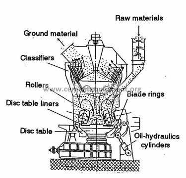
| The vertical roller mill has high energy efficiency and the installation space is smaller compared with tube mills. These days, the vertical roller mills have been widely adopted. A)Structure
B)Feature
Fig.2 Schematic process flow of vertical roller mill for grinding of raw materials
Vertical roller mills are adopted in 20 cement plants (44 mills) in Japan.
| |||||||||||||||||||||
| Results
| Table Energy saving effect of the vertical roller mill
| |||||||||||||||||||||
| Cost estimation | About 14million US$ [Newly-built] and about 230 million US$ [retrofitted], including the cost of supplemental facilities [200t-RM/h] [1US$=¥110] | |||||||||||||||||||||
| Related matters | ||||||||||||||||||||||
| References | ||||||||||||||||||||||

67
| Item | External circulating system to vertical roller mill | Application process | ||||||||||||||||||||||||||||||||||||||||
| Raw material process | ||||||||||||||||||||||||||||||||||||||||||
| Background | In the vertical roller mill which is widely used in the raw material grinding process, raw materials input grinding table are crushed and pulverized on it and transported to separator by kiln exit gas introduced into the mill as drying, transporting and separating purpose. In case that the proposed external circulating system is not installed, which is called conventional system, uncrushed and/or half crushed large size materials undergone rotating and grinding works on the table and jump out from it have to be kept above the table or transported to separator by the gas blown around the table to hold them in the mill inside until desired particle size by clinkering process is gotten. This internal material holding and separating works by the gas requires huge energy. It amounts about 60% of this raw material grinding process. Around 1980, it is proposed the external material circulating system that uncrushed large size raw materials jumped out from the table is re-transported by mechanical system in order to reduce gas blow and transportation energy. | |||||||||||||||||||||||||||||||||||||||||
| Descriptions | In case that the proposed external circulating system is provided to the vertical mill, the uncrushed materials jumped out from the table fall through gas inlet box to and collected by the mechanical transportation equipment installed below the mill such as chain conveyor and bucket elevator etc. And then they are re-transported to fresh material feed equipment to re-send the mill. Since the uncrushed raw materials are not blown-up by the gas, transportation energy of the gas, which is generated by mill fan, extremely decreases.
(Kiln gas exhaust fan)
Raw matarials Mill fan External circulating system Fig. Flow chart of roller mill adopting the external circulating system. | |||||||||||||||||||||||||||||||||||||||||
| Results | As compared with conventional internal circulating system, power consumed for fan is reduced until half and it’s possible to reduce power of grinding system by about 30%
Table The comparison of external circulating system
| |||||||||||||||||||||||||||||||||||||||||
| Cost estimation | It depends on scale of facilities. For example, about 820,000 US$ per unit. [1US$=¥110] | |||||||||||||||||||||||||||||||||||||||||
| Related matters |
| |||||||||||||||||||||||||||||||||||||||||
| Reference | ||||||||||||||||||||||||||||||||||||||||||

68
| Item | Direct dust collection system to vertical mill grinding process | Application process |
| Raw material process | ||
| Background | At the beginning stage when vertical roller mill was adopted to cement manufacturing, mill gas circulation fan and dust collection fan are required and their power consumption was larger. | |
| Descriptions | The conventional process gas flow of the mill grinding system generally consists of vertical roller mill with separator, cyclone, mill circulation fan, and electrostatic precipitator (EP) and EP fan as shown in Fig.1. Pulverized final products, which is called kiln feed raw meal, are collected at the cyclone and EP. Because of large pressure loss at the cyclone and in order to control mill gas flow, mill circulation fan and EP fan are provided after the cyclone and EP respectively. Power consumption of these two fans reaches about 10kwh/t-raw-material.
In the direct dust collection system shown in Fig.2, process flow is simple. The raw materials are dried and ground by the mill simultaneously in one-pass kiln exit gas and then fine product after separation is sent to EP directly. Since the cyclone is not installed, system pressure loss reduces. And as the mill fan treats de-dusted gas only, its power consumption largely decreases. As of 2002, this system is used at four plants in Japan.
(Kiln gas exhaust fan)
Vertical Mill Fi ne product Mill circulation fan Raw Mill EP Raw Mill EP fan
Chimney
Kiln IDF
Fig.1 Flow of Conventional Vertical Mill Grinding System
(Kiln gas exhaust fan)
Fine product Chimney Kiln IDF Vertical Mill Raw Mill EP Raw Mill EP fan
Fig.2 Flow of direct dust collection system
| |
| Results | Power consumption of fan(s) reduces about 3 to4 kWh/t. | |
| Cost estimation | When a mill with a production capacity of 420 t/h was newly constructed, the total cost was about 25 million US$. [1US$=¥110] | |
| Related matters |
| |
| Reference | ||


69
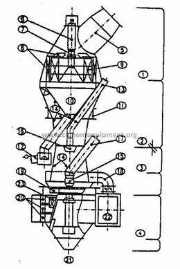
| Item | Pre-grinding equipment for raw material grinding process | Application process | ||||||||||||||||||||||||||||||||||||||||
| Raw material process | ||||||||||||||||||||||||||||||||||||||||||
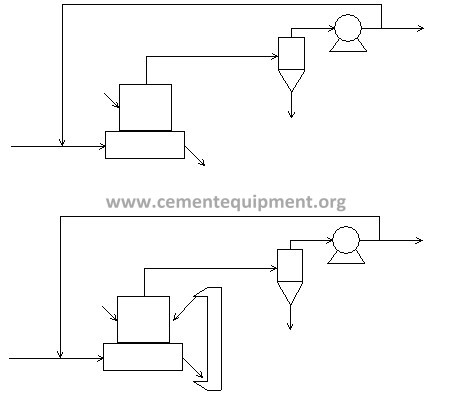
| Background | Recently, the vertical roller mill having great grinding performance is widely applied to the raw material grinding process. However, tube mill, which has about 30% poor grinding performance as power consumption, has been still used many existing cement plant. The improvement of this tube mill grinding system is highly expected.
| |||||||||||||||||||||||||||||||||||||||||
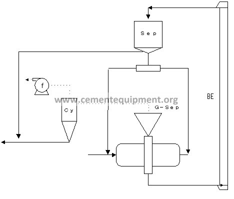
| Descriptions | The tube mill comminutes raw materials by impact and friction between grinding balls, which hit raw materials as well as between grinding ball and mill lining. Many of this type mills have two grinding chambers for coarse and fine grinding. Grinding ball size and their distribution are designed and adjusted considering raw material conditions and mill dimensions etc. However, the energy efficiency in the coarse grinding chamber is extremely poor and there is limitation to improve both performances for coarse and fine grinding on the same mill by ball size selection etc. Therefore, a new system was proposed and developed by installing a pre-grinder, which is roller mill or roller press, as coarse grinding before the existing tube mill, which is exclusively used for fine grinding. This system greatly reduced the specific power consumption and improved the production capacity. This system is now installed at three plants in Japan and improvement of production of 50 to 100% has been achieved when roll mill type pre-grinder is used. As the pre-grinder, vertical roller mill is often used considering its great grinding efficiency.
mill Mixed raw materials Pre-grinder
Coa r se
po w de r Coarse powder
Produc t Separ ator Fig. Raw material grinding system | |||||||||||||||||||||||||||||||||||||||||
| Results | Table Effect of implementing raw material pre-grinder
By this production increasing, it is expected that operation in the daytime can be shortened and then power cost can be reduced. | |||||||||||||||||||||||||||||||||||||||||
| Cost estimation | About 7.3 million US$ (depending on the scale) [1US$=¥110] | |||||||||||||||||||||||||||||||||||||||||
| Related matters | ||||||||||||||||||||||||||||||||||||||||||
| Reference | ||||||||||||||||||||||||||||||||||||||||||
70
| Item | Classification of powder returned from raw material separator | Application process |
| Raw material process | ||
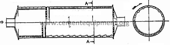
| Background | When raw materials are ground in a closed circuit by a double-rotator mill, grids remain underground in the second chamber for fine grinding, lowering the grinding efficiency.
| |
| Descriptions | The cause of this phenomenon is that grids contained in the separator returned power directly enters the second chamber. To separate grids from the returned powder and return them to the first chamber for coarse grinding, a simple grid screen (classifier) was installed at the return chute of the separator. The grids and coarse powder were ground with large balls. The ball diameter of the second chamber can be made small because only fine powder is returned to the room.
To EP
Coarse powder Fine powder
Refined powder
Raw materials First chamber Second chamber
Double-rotator mill
Fig. Classification of returned powder by double-rotator mill
| |
| Results | The work for removing grids from the second chamber can be mitigated. The decrease of power consumption rate is not remarkable but below 1 kWh per ton of raw materials. | |
| Cost estimation | 18,000 to 36,000 US$ per system [1US$=¥110] | |
| Related matters |
| |
| Reference | ||
71
| Item | Automation of raw material mixing control | Application process |
| Raw material process | ||
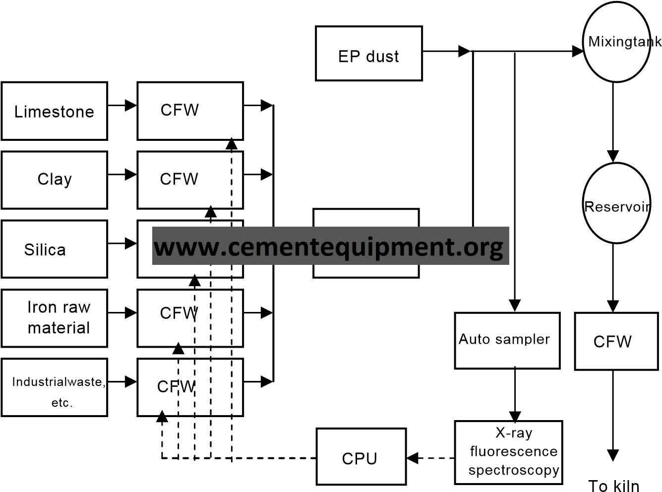
| Background | To keep the components of continuously produced raw materials at the targets is the most basic requirement for stable operation (energy conservation) and maintaining quality of production out of the burning process. Since the raw material mixing ratio must always be adjusted to keep the components of raw materials at the targets, an automatic control system was developed and implemented.
| |
| Descriptions | The basic management of the components of cement raw materials is to set the mixing ratio target based on the chemical composition of various raw materials and feed back the results of analyzing the components of raw materials and adjust precisely the mixing ratio. Therefore, an online automatic control system was developed and implemented by combining such systems as continuous measuring equipment, an automatic sampler, an X-ray fluorescence spectrometer of the glass bead method, and a computer program for mixing control.
| |
| Results |
| |
| Cost estimation | X-ray fluorescence spectrometer of the glass bead method: 0.9 to 1.8 million US$ [1US$=¥110] | |
| Related matters | ||
| Reference | ||
72
| Item | Optimization of raw material fineness | Application process | |||||||||||||||
| Raw material process | |||||||||||||||||
| Background | Raw materials used to be ground to a rather finer level because the fineness of them affects the clinker burning efficiency. Since the power consumption rate is high for the fine grinding of raw materials, great efforts were made to save energy by making raw materials coarse.
| ||||||||||||||||
| Descriptions | The fineness of raw materials used to be controlled at the level of several percents of 90 micron residue in the old wet process or others. As the burning method changed to SP and NSP, efforts were made to reduce the power consumption rate at the raw material process by increasing coarseness. These efforts resulted in great achievements. Since the fineness of raw materials affects the formation of hydraulic minerals at burning, increasing coarseness is naturally limited. If raw materials are made too coarse, however, free limes are likely to increase in clinkers and more heat is required to maintain the conventional level. To optimize the fineness of raw materials, therefore, it is important to find out the limit of making raw materials coarse under specific conditions.
Means of making raw materials coarse
| ||||||||||||||||
| Results | Achievement and estimated effect: The table below gives the results of calculation by Bond’s formula with the new feed size fixed.
| ||||||||||||||||
| Cost estimation | Basically, the above adjustment only | ||||||||||||||||
| Related matters | |||||||||||||||||
| Reference |
| ||||||||||||||||
73
| Item | Intermittent charging of electric dust collector | Application process | |||||||||||||||
| Raw material process | |||||||||||||||||
| Background | The conventional electric dust collectors use the continuous charging method. However, the intermittent charging method was developed to save energy and is now being implemented. To meet the following demand for more efficient electric dust collectors, the pulse charging method was developed and is now being implemented.
| ||||||||||||||||
| Descriptions | The intermittent charging method uses a waveform (semi-pulses) thinned out from the output of the continuous charging method periodically. Thinning out the output saves power. In addition, the dust collection efficiency is said to be a bit superior to that of the continuous charging method and the alteration cost is not high because only the control device of the continuous charging method should be altered. The reduction of dust collection efficiency of electric dust collector became unsatisfying as coal ashes and other wastes having great electric resistance and fine particles of submicron-level diameters were used in greater amount. Under these circumstances, the pulse charging method was implemented to save power and improve the dust collection efficiency. The pulse charging method uses a voltage waveform where pulses are superposed on a DC voltage. The DC voltage, pulse voltage, and period are controlled. This method costs higher than the others.
As of 1996, 120 systems use continuous charging, 21 systems use intermittent charging, and 16 systems use pulse charging in Japan.
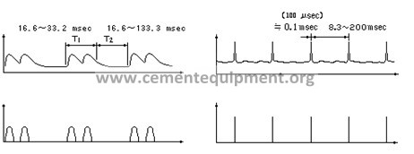
Pulse charging
Voltage Time Time Current
Current Voltage Time Time | ||||||||||||||||
| Results |
| ||||||||||||||||
| Cost estimation |
| ||||||||||||||||
| Related matters | |||||||||||||||||
| Reference | |||||||||||||||||
74
| Item | Transportation of raw materials for input into kiln | Application process |
| Raw material process | ||
| Background | For a kiln with preheater, such as SP or NSP, mixed raw materials are transported to the top of the preheater and then fed into the system. When the SP kiln was developed, air compression transpotation by a Quinion pump was initially adopted. Because of great pressure loss, high power consumption rate, and frequent compressor faults, however, a more reliable and efficient method was expected.
| |
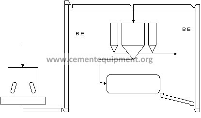
| Descriptions | Compressed air transportation was replaced with mechanical transportation such as a combination of bucket elevator (BE) and air slider (AS). Two or three Bes are installed up to the top of the preheater. Raw materials are lifted to the top by changing the Bes and fed into the preheater through the AS. BE has small no-load power because of its structure and AS is a means of transportation using the self weight of powder. Therefore, this method can reduce power consumption greatly compared with air compression delivery. Air compression transportation used to cause great fan power loss because of large volume of compressed air flowing into the system with raw materials. Mechanical transportation can minimize the air inflow. The initial BE used a short-link chain that caused many problems of abrasion or elongation. A plate-type chain reduced these problems greatly and achieved the current high reliability.
As of 1996, 72 systems use mechanical transportation and two systems use air compression transportation in Japan.
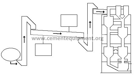
Guided-discharge bucket elevator Preheater
Dust collector Air slider Powder
Blower To kiln
| |
| Results | Mechanical transportation reduced power consumption by even 80%, although depending on the distance of transportation. | |
| Cost estimation | Bucket elevator (2 units): About 1.4 million US$ [1US$=¥110] (For a kiln having a capacity of 3000 t/d) | |
| Related matters | ||
| Reference |
| |
75
| Item | The new suspension preheaters burning system | Application |
| Burning process | ||
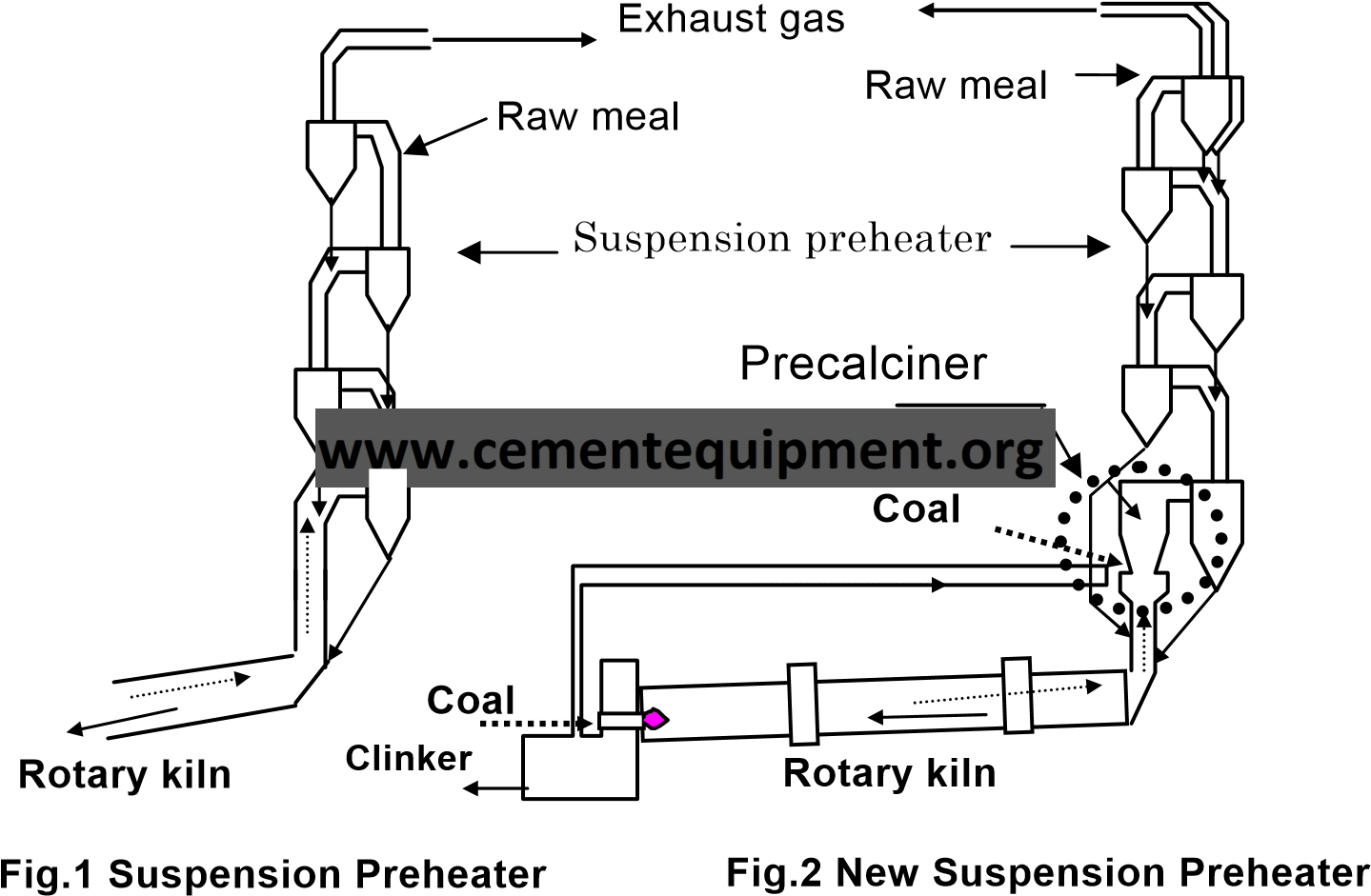
| Background | Clinker burning system for has switched from wet-process kilns to more efficient suspension pre-heater (SP) type since 1965. But in an SP burning furnace, all materials were fully combusted at once and this gave damage to the refractory inside. Besides with the increasing cost for maintenance, adhesion troubles in the pre-heater arouse, and it hindered from long time operation or capacity expansion. | |
| Descriptions | To solve those problems, a separate pre-calciner was installed within suspension preheater, which enabled reduction of specific energy consumption per unit clinker by 5060%. This technology was developed and applied in Japan. With SP type burning furnace, the raw materials were only 20-30% calcined at the kiln gate. While with the NSP type, it reaches over 90%. This reduces heat energy consumption in the rotary kiln for clinker production to approximately 40-50%, enhance production level, and mitigate damage to the refractory materials in the kiln. NOx emission levels are also reduced. These days, up to 320 days operation a year became possible thanks to this technology.
| |
| Results |
SP type burning furnace 4,000t/d; NSP type 10,000t/d
SP type burning furnace 3,470~3,600kJ/kg; NSP type 2,930~3,350kJ/kg
SP type burning furnace 800~900g/t-cl; NSP type 500~600g/t-cl | |
| Cost estimation | About 273 million US$ for new facility from “Raw material process” to “Burning process” [4000t-clinker/d] [1US$=¥110] | |
| Related matters | ||
| Reference |
| |
76
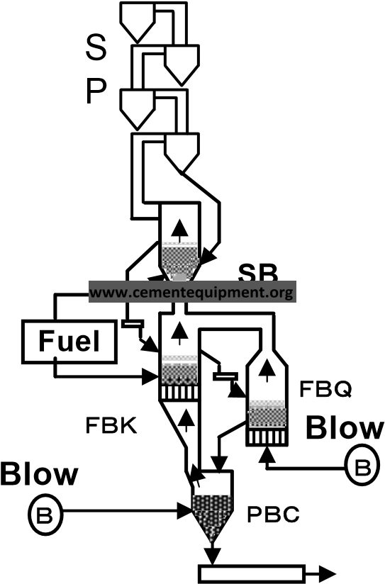
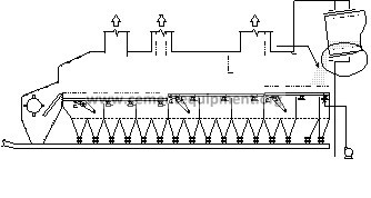
| Item | Fluidized bed cement kiln system | Application |
| Burning process | ||
| Background | In cement manufacturing, global environmental preservation such as the reduction of greenhouse effect gas (CO2) emission is required in addition to the reduction of NOx and SOx emission these days. Furthermore, the cement market needs to produce special cements such as high compressive strength cement and early hardening cement. In response to these needs, the fluidized bed cement kiln system has been researched and developed to comply with the global environment preservation since 1989. | |
| Descriptions | The fluidized bed cement kiln system consists of the following equipment:
for quickly cooling down the burnt clinker from 1400°C level to 1000°C in order to get good quality.
for efficiently recovering the sensible heat of clinker and cooling down the clinker to the specified temperature. Stoc
| |
| Results | 1)Economic advantages
2) Lower environmental pollution
| |
| Cost estimation | ||
| Related matters | ||
| Reference | ||
77
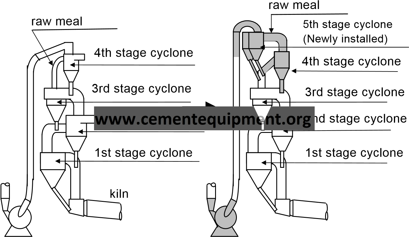
| Item | 5-stage system of suspension preheater | Application | ||||||
| Burning process | ||||||||
| Background | The suspension pre-heater is multistage heating system, using exhaust gas. In case of 4-stage, the temperature of gas at the outlet of the pre-heater is around 400℃. This exhaust gas is used for drying raw materials. The unexploited heat is let out after himidiffication. For achieving energy saving, remodeling of pre-heater from 4stage to 5-stage is carried out. | |||||||
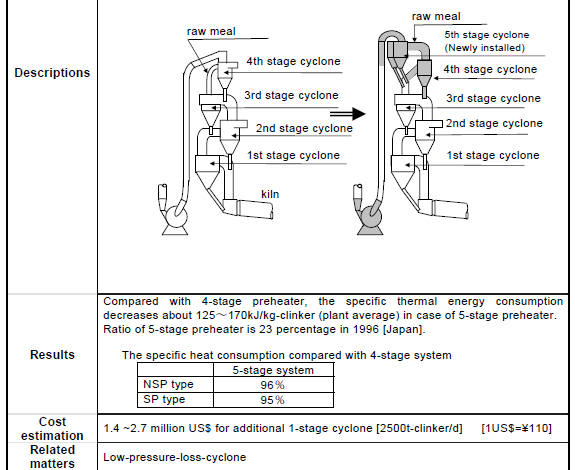
| Descriptions | There are two cases for 5-stage preheater. One is remodeling and the other is the adoption of 5-stage preheater in the case of new construction of kiln. By addition of one cyclone, the temperature of gas at the outlet of the preheater is decreased about 30~50℃. By adopting the 5-stage system, heat exchanging ability increases and the heat efficiency of the total system increases. As results, the specific heat consumption decreases. This technology usually applies to small capacity kilns that power station by the waste heat is not economically applicable.
The example of remodeling
| |||||||
| Results | Compared with 4-stage preheater, the specific thermal energy consumption decreases about 125~170kJ/kg-clinker (plant average) in case of 5-stage preheater. Ratio of 5-stage preheater is 23 percentage in 1996 [Japan].
The specific heat consumption compared with 4-stage system
| |||||||
| Cost estimation | 1.4 ~2.7 million US$ for additional 1-stage cyclone [2500t-clinker/d] [1US$=¥110] | |||||||
| Related matters | Low-pressure-loss-cyclone | |||||||
| Reference | ||||||||
78
| Item | Improvement of the calciner | Application |
| Burning process | ||
| Background | A calciner installed at a suspension preheater consumes about 50 to 60% of necessary heat to promote the thermal decomposition of limestone in raw materials. When NSP was popular, the main fuel was heavy oil and the calciner was also designed according to the combustion characteristics of heavy oil but has been optimized according to the change of fossil fuel after the Oil Shock in 1970s.
| |
| Descriptions |
For cost reduction, the use of oil coak and other fuels of low combustibility are increasing these days. To improve their combustibility, high temperature to some extent is necessary. To improve temperature distribution in the calciner, some measures are taken: Making the tertiary air from the cooler hot (raising the cooler efficiency), Reducing the grain size of pulverized coal, and Raising the burner efficiency and optimizing the setting position.
(A) (B) (C)
cyclone
Effective volume of the calciner V = 169 m3 V = 230 m3 V = 460 m3
Example of improvement
| |
| Results |
| |
| Cost estimation | 3 to 4 million US$ (Burning capacity: 3,000 t/d) [1US$=¥110] | |
| Related matters | Improvement of burning in calciner | |
| Reference | ||

79
| Item | Improvement of burning in calciner | Application |
| Burning process | ||
| Background | For a calciner, coal of comparatively high volatility used to be used. To meet the demand for less expensive fuels, the combustion technology has been improved to use coal of low volatility. | |
| Descriptions | When a fuel of low volatility is used under the conditions for a fuel of high volatility, the burning temperature of the calciner falls and the outlet gas temperature of the bottom cyclone rises as the burning time becomes long. Since the production output and the heat consumption rate deteriorate, technological development was promoted to utilize a fuel of low volatility.
To improve burning in a calciner, the following technologies are adopted:
Rotary Kiln
Combustion Chamber
Mixing Chamber
Diverting Damper
Burner
Tertiary Air
Example of split raw meal feeding
| |
| Results |
| |
| Cost estimation | 1) Burner alteration: 10 to 50 thousand US$ [1US$=¥110] | |
| Related matters | Improvement of the calciner | |
| Reference | ||
80
| Item | Automatic control of bottom cyclone outlet temperature | Application |
| Burning process | ||
| Background
| For a stable kiln operation, it is necessary to keep almost constant the decomposition (decarbonization) rate of raw materials input into the kiln. The outlet temperature of the bottom cyclone is used as an operation index on behalf of the decomposition rate and the kiln is operated to keep its transition stable. Since the outlet temperature varies with various factors, such as the fluctuation of heat value of the fuel, it is difficult to deal with all fluctuations manually. This is why technology such a automatic control was put to practical use. | |
| Descriptions |
Outlet gas temperature control flow of bottom cyclone
| |
| Results | The heat consumption for burning clinkers goes down by 0.8%. | |
| Cost estimation | ||
| Related matters | ||
| Reference | ||
81
| Item | Chlorine bypass system | Application |
| Burning process | ||
| Background | Chlorine contained in cement raw materials is evaporated by a high-temperature section in the kiln and condensed at the lower part of the preheater where the temperature is comparatively low. This is repeated for condensation up to about 200 times. By reaction with raw materials, chlorine or sulfur generates various compounds of low melting points and forms scales (coating) on the internal wall of the preheater, causing such process problems as an increase of ventilation resistance and clogging in the cyclone. Drastic measures were necessary to prevent these problems from causing great energy losses. | |
| Descriptions | The cause of scales deposited in the preheater corresponds to the melting point of compound and the temperature distribution of the preheater. Scales in the rising duct is mainly attributed to sulfide and those in the cyclone to chloride. Their excessive resistance causes a serious problem synergetically. Chlorine bypass is a technology to efficiently recover chlorine from the lower part of the preheater where chlorine is condensed most. Raw materials are partially extracted or gas is extracted to recover fine dust. Chlorine recovery reduces the chlorine condensation in raw materials and solves or mitigates the formation of scales attributable to chlorine condensation.
As of 2000, the implementation rate was 54% and the gas bypass method accounted for 80% of them. The bypass rate was 1 to 3% for 74% of the gas bypass systems and 1% or less for all of the raw material bypass systems.
Gas bypass system
| |
| Results |
| |
| Cost estimation | Chlorine bypass system for a daily output of 5,000 tons (clinker basis): About 3.2 to 4.5 million US$ [1US$=¥110] | |
| Related matters | Cyclone descaler | |
| Reference | ||
82
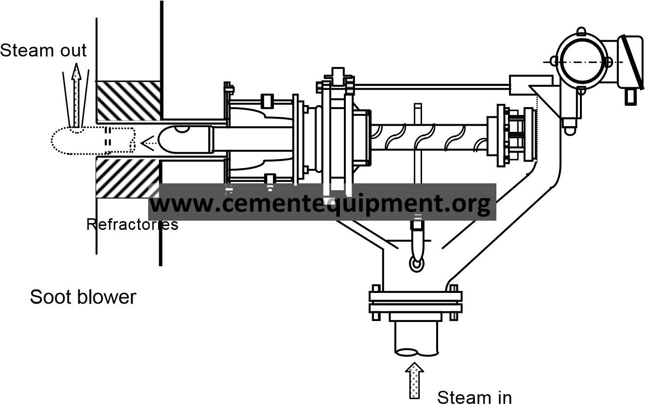
| Item | Cyclone descaler | Application |
| Burning process | ||
| Background | Chlorine, alkali, or sulfur contained in cement raw materials and fuels evaporates in a high-temperature section of the kiln and condenses at the lower part of the preheater. This phenomenon is repeated such elements and gradually concentrate. Reaction of these with raw meal generates various compounds of low melting points and forms scales (coating) on the internal wall of the preheater, causing such process problems as an increase of ventilation resistance and clogging in the cyclone. Various measures were taken to prevent these problems from causing great energy losses.
| |
| Descriptions | A descaler was adopted to prevent the growth of scales deposited on the internal wall of the preheater.
The descalers are installed at many locations where manual cleaning is difficult or the scale is deposited severely and activated periodically to prevent the growth of scale.
In this example, the internal cylinder thrusts and withdraws. After thrusting, the cylinder tip rotates and blows steam out.
| |
| Results | 1) This is effective for preventing the growth of scale, but the effect differs individually. 2) The work load of preheater cleaning can be reduced. | |
| Cost estimation |
| |
| Related matters | Chlorine bypass system | |
| Reference | ||
83
| Item | Combustion management | Application |
| Burning process | ||
| Background | The clinker burning process consumes great thermal energy to make clinker. Fuels combustion management is the most fundamental energy-saving activity to be conducted everyday at cement plants. | |
| Descriptions | Combustion management approaches are made from various aspects relating to combustion.
The main fuel used in Japan is coal and its supply sources are selected, taken into consideration the price, fuel ratio (fixed carbon to volatile matter), and Hard Grobe Index (HGI). Technically speaking, the capacities of grinding mills, performance of burners, burner performance, volume of calciner, and other items relating to fuel combustion should be considered enough at the time of selection.
According to the combustion characteristics of fuels, fuel grinding should be managed to achieve fineness appropriately set. In particular, the separator should have high classification performance because the mixing of coarse particles increases noncombusted part of coal.
For complete fuel combustion, air beyond the theoretical volume is required when actual operation is made. If too much air is supplied, however, thermal energy necessary for its heating becomes a loss. To maintain an appropriate air ratio, the oxygen concentration in the combustion exhaust gas requires strict management. Oxygen densitometers are installed at the kiln inlet, exhaust gas outlet of the preheater, etc. For gaining values, they should be checked periodically and maintained properly.
In addition to the above oxygen management, CO and NOx are measured and their measurement data are used for combustion management. NOx is generally said to reflect the temperature of a burner flame but requires appropriate management because its emission concentration is regulated.
According to the combustion characteristics of fuels, the basic designs such as the fuel discharge angle of the burner, the primary air ratio, etc., should be reviewed to maintain the optimum combustion conditions. Even during operation, it is necessary to optimize the frame shape by changing the burner set position, adjusting the primary air ratio, etc. according to a fuel change.
Heat recovery at the cooler greatly affects the combustion management of the kiln burner. Therefore, scheduled maintenance and adjustment and management in everyday operation are important.
| |
| Results | The thermal energy utilization efficiency is improved. (The heat consumption goes down.) | |
| Cost estimation | ||
| Related matters | ||
| Reference | ||
84
| Item | Stabilization of coating in kiln | Application |
| Burning process | ||
| Background | Coating formed on the brick working surface in the kiln burning zone lowers the shell temperature to reduce radiant heat and protects the brick. Unstable coating easily leads to a brick problem and generates an energy loss by disturbing stable run. | |
| Descriptions | Various measures are taken to form and maintain stable coating in the kiln burning zone.
One of the causes of unstable coating is the fluctuation of components in supplied raw meal. For a kiln of unstable coating in the burning zone, the fluctuation of components in raw meal should be checked and corrective measures should be taken if the fluctuation is great.
If the fuel is changed unreadily to a brand of greatly different combustion characteristics, the frame pattern will change greatly and the coating may break. It is also important to prevent the blow-in rate from fluctuating.
Where the burning conditions change periodically, breakage of coating easily occurs. Since hunching is often attributable to the fluctuation of the clinker cooler, it is necessary to stabilize the cooler operationj
If the combustion performance of the kiln burner is low, coating generally does not adhere and easily breaks from a slight heat shock. If coating comes off frequently, the burner performance should also be noted.
The deposition of coating also differs depending on the brick quality. The lining position should be determined by considering that spinel bricks are less adhesive than magnesia-chrome bricks.
Coating is considered to form when liquid-phase mineral of high temperature contacts with and cooled by the brick working surface and becomes solid. It is thought that coating deposition can be strengthened by cooling the shell temperature forcibly to reduce the temperature of the brick working surface. Both air cooling and water cooling are in practical use.
| |
| Results |
| |
| Cost estimation | Kiln shell air-cooling equipment: about 91 thousand US$ [1US$=¥110] | |
| Related matters | ||
| Reference | ||
85
| Item | Strengthened air sealing at kiln outlet | Application |
| Burning process | ||
| Background | The kiln outlet shell is structurally a free end under very severe thermal conditions, being exposed to high-temperature clinker and radiant heat from the refractories in the cooler hood. If the outlet shell has cracks, opens a bell shape and causes a great losses like a kiln stoppage by bricks drop. To protect the kiln outlet shell, the lining refractory of appropriate quality, fixing tip casting, and forced air cooling is adopted in general. If air sealing at the outlet is not adequate, cool air leaks into the cooler, lowers the secondary air temperature, and deteriorates the heat consumption.
| |
| Descriptions | The kiln outlet has a dual-shell structure where forced cooling is made by air from an exclusive fan or branched fan from a cooling fan of the clinker cooler. To prevent part of the air after heat exchange from leaking into the cooler and lowering the secondary air temperature, a spring-type seal or brush type air seal is adopted.
Air leakage at the kiln outlet produces a much greater influence than that at any other section because it not only lowers the combustion efficiency of the burner but also increases the fuel consumption to heat the leaked air. Air leakage at the outlet must be minimized.
Fig.1 Schematic of the kiln mouth
Kiln shell Cooling air A ir sealing
Tip casting Exhaust air from cooler
To coal dryer Tertiary air for calciner Clinker Kiln Cooling fan of each chamber
Fig.2 Air seal at the kiln outlet (Brush type air seal)
As kiln outlet refractories, refractory castables and fired spinel bricks are popular. SCH13 occupies the greatest percentage used for the tip casting. | |
| Results | As the leaked air was reduced by 160Nm3/min, the heat consumption became about 42 kJ/kg-cl (10 kcal/kg-cl ) less. | |
| Cost estimations | 50 thousand US$ (5,000t/d) [1US$=¥110] | |
| Related matters | ||
| Reference | ||
86
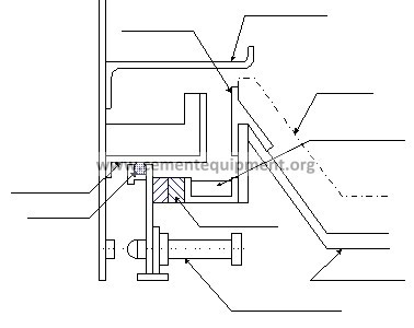
| Item | Strengthened air sealing at kiln inlet | Application |
| Burning process | ||
| Background | Air leakage into the cement manufacturing process deteriorates the heat and power consumption. Since the air leakage at the inlet of the kiln cools high-temperature combustion exhaust gas and lowers the heat value greatly, it is important to prevent air from leaking in.
| |
| Descriptions | Air sealing at the inlet of the kiln has a structure to mechanically prevent kiln shell rotation and thermal expansion from causing a gap. The figure shows an example of air sealing structure.
Brick
Raw meal lifter
Kiln shell
A ir cylinder
Slide plates
Packing Brick retainer Brick retainer Preheater
Structure of air sealing at the kiln bottom
| |
| Results | The deterioration of heat and power consumption is prevented. | |
| Cost estimations | 0.2 million US$ (kiln diameter: 6 m) [1US$=¥110] | |
| Related matters | ||
| Reference | ||
87
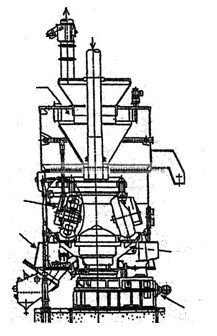
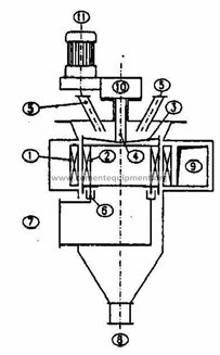
| Item | Vertical coal mill | Application |
| Burning process | ||
| Background | Tube mill had been used for coal grinding. Steel balls were used as the grinding media, and tube mill should have enough room to allow attrition between the balls and coal. This result in higher initial costs, higher electricity consumptions and limits the downsizing of the tube mill. | |
| Descriptions | In a vertical coal mill, drying, grinding, and separating/classifying of coal can be done simultaneously. Hence, production and energy efficiency is higher. This technology became popular after oil shock time, when the fuel switched from oil to coil.
Pulverized coal exit [air sliders]
Roller
Classifier Table
Air entrance for dryness
Motor reducer | |
| Results | Capable of reducing electricity consumptions for coal grinding by 20-25%. | |
| Cost estimation | About 9 million US$ including cost of supplemental facilities [20t-coal/h] [1US$=¥110] | |
| Related matters | ||
| Reference | ||
88
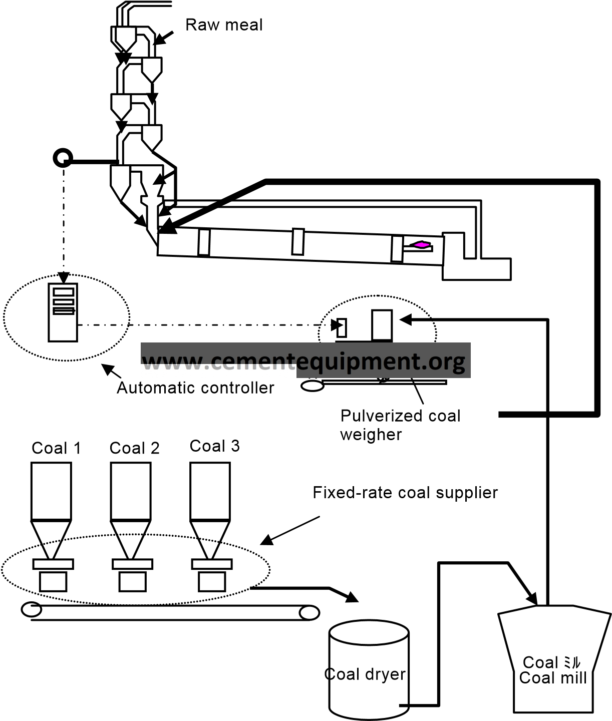
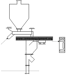
| Item | Pulverized coal constant feeder | Application |
| Burning process | ||
| Background | The accuracy of constantly feeding pulverized coal to a cement rotary kiln affects the stability of the burning process and the cement quality. The selection and daily maintenance of feeding and measuring devices are extremely important.
| |
| Descriptions | The constant feeders for pulverized coal now used in Japan can be classified into the following types. Both types feature high feeding accuracy within ±1% and high momentary accuracy as well.
This is a combination of a volumetric table feeder and a weighing hopper that calculates the table feeder discharged amount from the weight reduction speed of the table feeder for constant feed. There is a horizontal rotation table under the hopper. Pulverized coal on the table is scraped off by the scraper board while being rotated with the table. The feed amount is adjusted by the press-in depth of the scraper board.
The impact flowmeter is based on the principle that the horizontal component with impaction force of naturally falling pulverized coal on the detection plate is proportional to the momentary weight flow rate.
Feeder
Impact line Microcomputer line
An impact flowmeter is combined with a screw feeder which enables constant feeding by controlling the screw feeder rotation speed.
An impact flowmeter is combined with a table feeder which enables constant feeding by controlling the table feeder rotation speed.
A loop-shaped conveyor itself has a balance structure. This conveyor has a powder inlet on one side and a powder outlet on the other side with both ends of the centerline as fulcrums. Since the mechanical structure of either sides of the fulcrum is uniform, the tare is canceled. Figure: Constant feeder (impact flowmeter)
| |
| Results | Stable constant feed free of flushing or pulsation is realized. | |
| Cost estimation | ||
| Related matters | ||
| Reference | ||
89
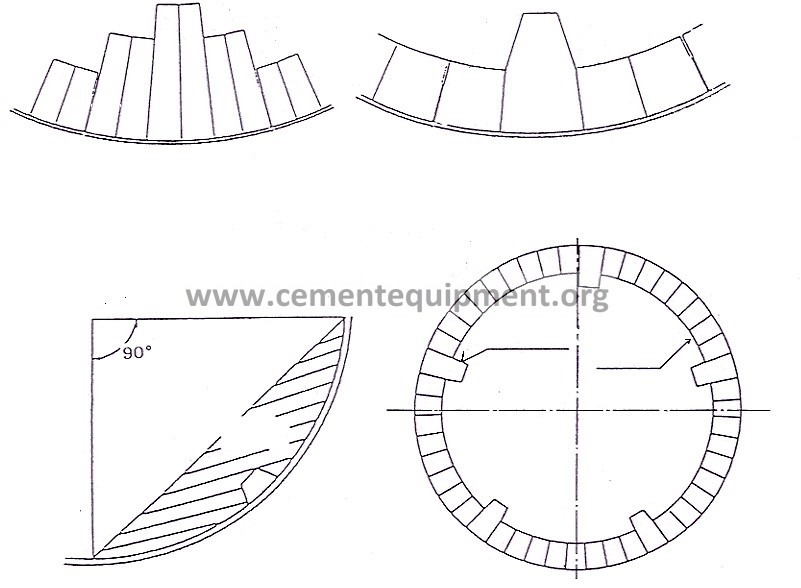
| Item | Adoption of lifter brick | Application |
| Burning process | ||
| Background | To improve thermal efficiency in the calcinating zone of a kiln and to prevent the deposition of coating to the preheater by a temperature decrease of the kiln bottom gas, four or more bricks are projected per circle to stir raw materials.
| |
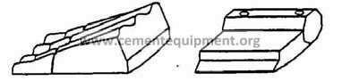
| Descriptions | Four or more lifter bricks per circle are projecting 100 to 200 mm out of the base bricks in the calcinating zone to stir raw materials and promote their heat exchange. In addition, the full conduction of thermal energy to raw materials is expected to lower the kiln bottom temperature and reduce coating deposition to the preheater. As shown in Fig.1, the lifter brick have an arc shape when the base bricks have an arc shape or a sector shape when the base bricks have a sector shape. Since the lifter bricks are projecting out of the base bricks, their projections easily crack or spall due to abrasion, thermal stress, or mechanical stress. Therefore, the service lives of lifter bricks have been extended by improving the material. Regarding the number of lifter bricks per circle, there must always be lifter bricks in the raw material beds as shown in Fig.2 because they must stir raw materials without letting them slip on the bricks in the kiln. If the filling factor of raw materials in the kiln is assumed to be 10%, the central angle of the raw materials is about 90°. Then at least four or more lifter bricks are necessary per circle. (As the kiln diameter is greater, more lifter bricks are necessary.) The lifter brick installation is mainly 2 to 10 m. The locations are not fixed but usually almost from 0.1 to 0.4 if the kiln bottom is 0 and the kiln mouth is 1.
Lifter brick shapes Arch type
Sector
Raw materials Lifter brick
Base brick
Fig.2 General view of lifter brick and the number of bricks installed | |
| Results | Deposition to the preheater decreased because the kiln end temperature was lowered 50 to 100°C. | |
| Cost estimation | Usually high-alumina brick = 640 to 820 US$ [1US$=¥110] Lifter brick = 1,800 to 2,700 US$ [1US$=¥110] | |
| Related matters | ||
| Reference | ||
90
| Item | Heat insulation of refractories | Application |
| Burning process | ||
| Background | For high-temperature burning in the burning process, reftractories are used for the internal walls of various facilities. Various heat insulation measures are taken to prevent heat radiation losses from walls. | |
| Descriptions | The heat dissipation loss at the burning process corresponds to about 4% to 6% of the thermal energy. To reduce this loss, heat insulation measures are taken according to each section.
In this zone, burnt products are the hottest and coating is deposited on the surfaces of refractories (bricks) to protect the bricks and insulate heat. Therefore, the heat insulation measures in this zone is to form and maintain stable coating.
In this zone where coating is frequently deposited and defoliated, spinel bricks of great thermal conductivity advantageous for long-life bricks are often used and the shell temperature is high. Therefore, the following measures were aggressively attempted to insulate spinel bricks thermally.
All of the above measures, however, have a problem in life and almost none of them is now in use.
For the calcinating zone of comparatively low temperature, refractory heatinsulating bricks of low thermal conductivity are used, as well as the conventional refractory bricks made of high alumina or clay. The refractory heat-insulating bricks are also burnt or not burnt according to the purpose of use.
Excluding the lower part of the preheater where the temperature is comparatively high, the two-layer structure is used with heat-insulating castables on the back. A wet spraying process for castables was recently developed and the construction efficiency is being improved.
Two-layer heat insulation is applied with a heat insulator of calcium silicate on the back.
| |
| Results | Heat dissipation decreased with a decrease of the kiln surface temperature. | |
| Cost estimation |
| |
| Related matters | Stabilization of coating in kiln | |
| Reference | ||
91
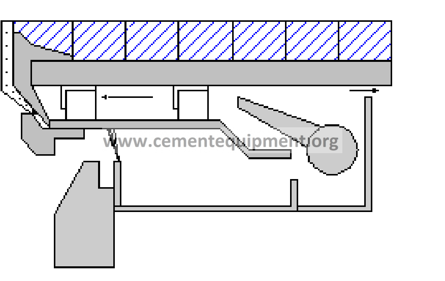
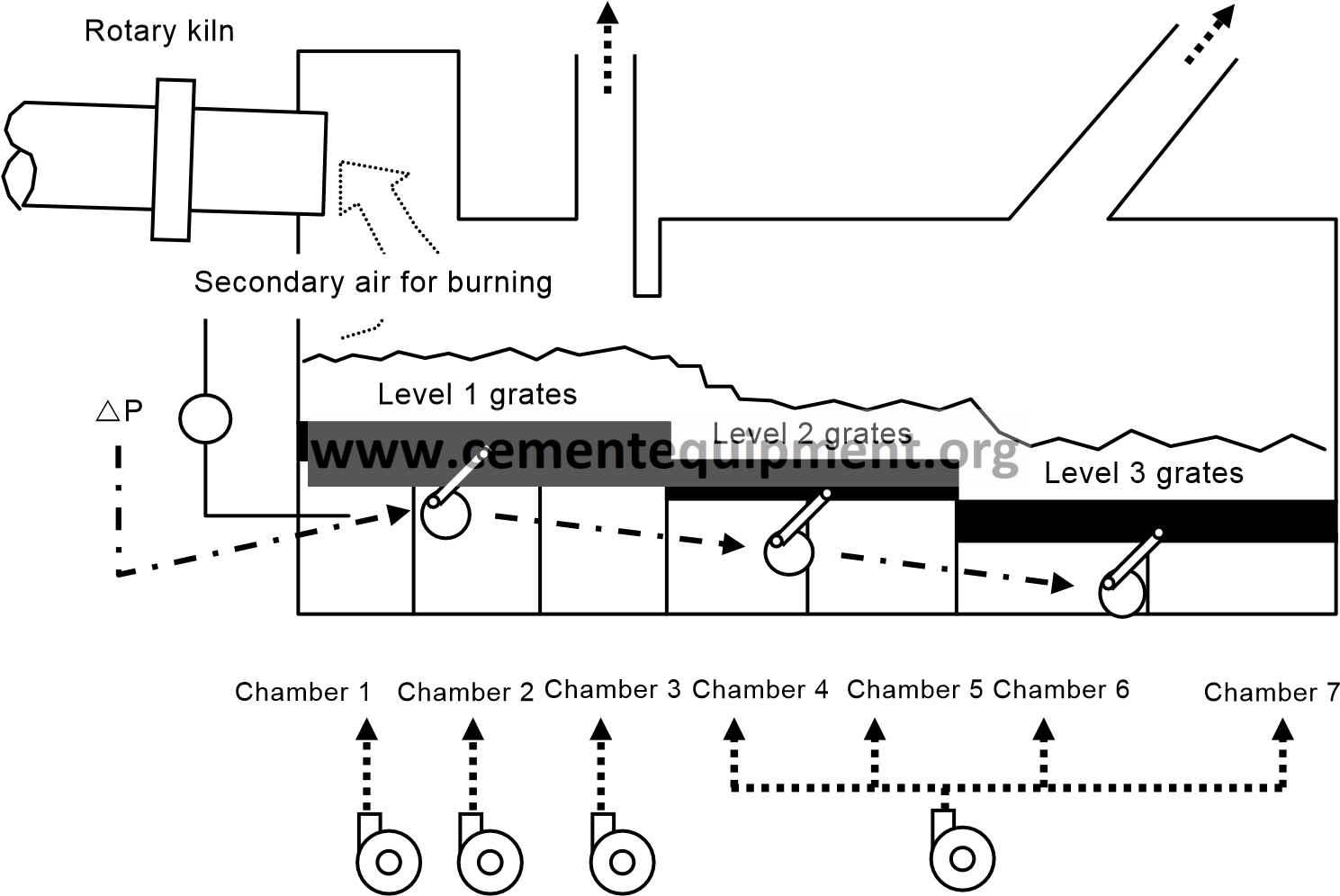
| Item | Cooler width control | Application |
| Burning process | ||
| Background | With a production capacity increase by the implementation of the SP and NSP methods, the grate-type clinker cooler also became large. Since the effective width of the cooler was too large for the clinker drop width, the problems of cooling air blowing through and heat spot occurred simultaneously. The blow-through problem lowers the secondary air temperature and the heat spot damages the grates. To prevent these problems from disabling stable run, the cooler was altered.
| |
| Descriptions | As a solution to these problems, width control was attempted to adjust the substantially effective width of the cooler appropriately. Through a lot of experiences, individual companies have established their unique technologies.
Width control is a basic technology to optimize a grate cooler of the air chamber type. However, the same concept applies to the air-beam cooler recently becoming prevalent.
Rotary kiln
Holed grate
Fixed (no-hole) grate installation position
Figure: Width control (arrangement of holed grates and fixed grates with no holes)
| |
| Results |
| |
| Cost estimation | 64,000 US$ [1US$=¥110] | |
| Related matters | Automatic AQC speed control Air-beam cooler | |
| Reference |
| |
92
| Item | Automatic control of AQC grating speed | Application |
| Burning process | ||
| Background | Recovering the hot secondary air and transporting clinkers are the two important functions of a clinker cooler. For the balanced execution of these two functions, it is necessary to always maintain the clinker layer of appropriate thickness on grates.
| |
| Descriptions |
Coal mill cooler Calciner secondary air exhaust fan
Figure: Outline of automatic AQC speed control
| |
| Results | The thermal recovery efficiency was improved by maintaining appropriate layer thickness (heat consumption rate down).
| |
| Cost estimation | ||
| Related matters | Cooler width control | |
| Reference |
| |
93
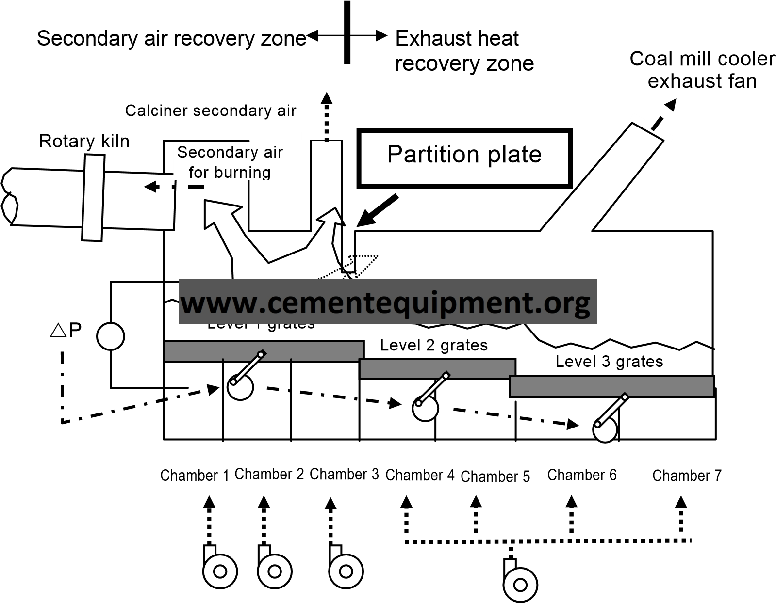
| Item | Installation of partition plates | Application |
| Burning process | ||
| Background | A clinker cooler is divided into an area where cooling air equivalent of the necessary air volume is blown in (hereinafter, the secondary air recovery zone) and the succeeding area (hereinafter, the exhaust heat recovery zone). To recover the secondary air of high temperature in the clinker cooler, the efficiency of heat recovery from the former area should be maximized.
| |
| Descriptions | Since the hot clinkers on grates are cooled from the lower layer, the top of the clinker layer remains hot in the secondary air recovery zone and dissipates heat much by radiation.
Figure: Installation of AQC partition plates
| |
| Results | The thermal recovery efficiency was improved by maintaining appropriate layer thickness (heat consumption rate down). | |
| Cost estimation | 45,000 US$ [1US$=¥110] | |
| Related matters | Cooler width control | |
| Reference |
| |
94
| Item | Air beam type clinker cooler | Application |
| Burning process | ||
| Background | Improvement of heat recovery rate for secondary or tertiary air from the heat in clinker is one of the most important technologies in the burning process. As heat recovery rate in conventional grate coolers are approximately 50 to 60 %, more improvement has been desired. | |
| Descriptions | When high temperature clinker is dropped on the grate of cooler from the outlet of kiln, it is not in flat or balanced. With the conventional cooler, cooling air is supplied to each air chambers, therefore, improvement of heat recovery rate is limited by imbalance of cooling air.
This problem is solved by installing air beam type cooler which has unique point as follows;
recovery area.
As cooling air is controlled for each block, air distribution can be optimized. Therefore, heat recovery rate is improved and the life of grate plate is extended.
By 2000, these types of coolers have been installed into approx. 30% of Japanese cement plants. Most of them (71%) have been installed at kiln outlet part of existing cooler. For 57% of these cases, improved heat recovery rate is not more than 5 %. In case only installed at kiln outlet part, improvement rate cannot be adequate. Fixed Movable Fixed Movable
Clinker layer
For Movable beam Fixed beam Air chamber
Clinker layer
Air chamber type Air beam type Comparison of cooling air supply | |
| Results |
| |
| Cost estimation | About 2.7 ~4.5 million US$ for 1-stage cooler retrofitting [1US$=¥110] | |
| Related matters | ||
| Reference |
| |
95
| Item | Automatic measuring device for free lime in clinker | Application |
| Burning process | ||
| Background | As well as the bulk density (liter-weight) of clinker, free lime (herein after, f-CaO) content in clinkers is an important factor to know clinker quality and clinkering conditions. f-CaO measurement used to be performed a few times a day by chemical analysis method. However, implementing an automatic measuring device remarkably increases the measuring frequency to 24 times a day or more. The volume of information about the clinker quality and clinker condition increases. By reflecting this information, stabilization of clinker quality can be gotten and then heat consumption of the kiln process can be reduced.
| |
| Descriptions | For the automatic online measurement of f-CaO in clinkers, the following two methods are known:
This method is based on a technology developed in Japan. Prepared representative clinker sample are ground into fine particles and molded by press. Then the diffraction strength of CaO is measured by using an X-ray diffraction device to determine the f-CaO concentration (content). In this method, clinker chemical components can be analyzed from same molded sample on X-ray fluorescence spectrometer. Unlike the chemical analysis method or electrical conductivity method, no chemical agents (solvents) are necessary for treatment.
CaO + (CH2OH)2 → Ca2+ + (CH2O)22- + H2O Ca2+ and (CH2O)22- give conductivity to the solution. Since these ions indicate conductivity proportional to the concentration, the amount of f-CaO in clinkers can be estimated by measuring the conductivity.
Prepared representative clinker sample is transported to a f-CaO measuring device and ground by a disk mill. Fixed amounts of the clinker powder and the ethylene glycol solvent are put into beaker and the electrical conductivity is measured.
| |
| Results | By reflecting the tendency of f-CaO data transition in running operation, the clinker quality can be stabilized and the kiln heat consumption rate can be reduced. As of Year 2000, the implementation rate is 35% (electrical conductivity method: 57%, X-ray diffraction method: 43%).
| |
| Cost estimation |
| |
| Related matters | Automatic measurement of clinker bulk density (liter-weight) | |
| Reference | ||
96
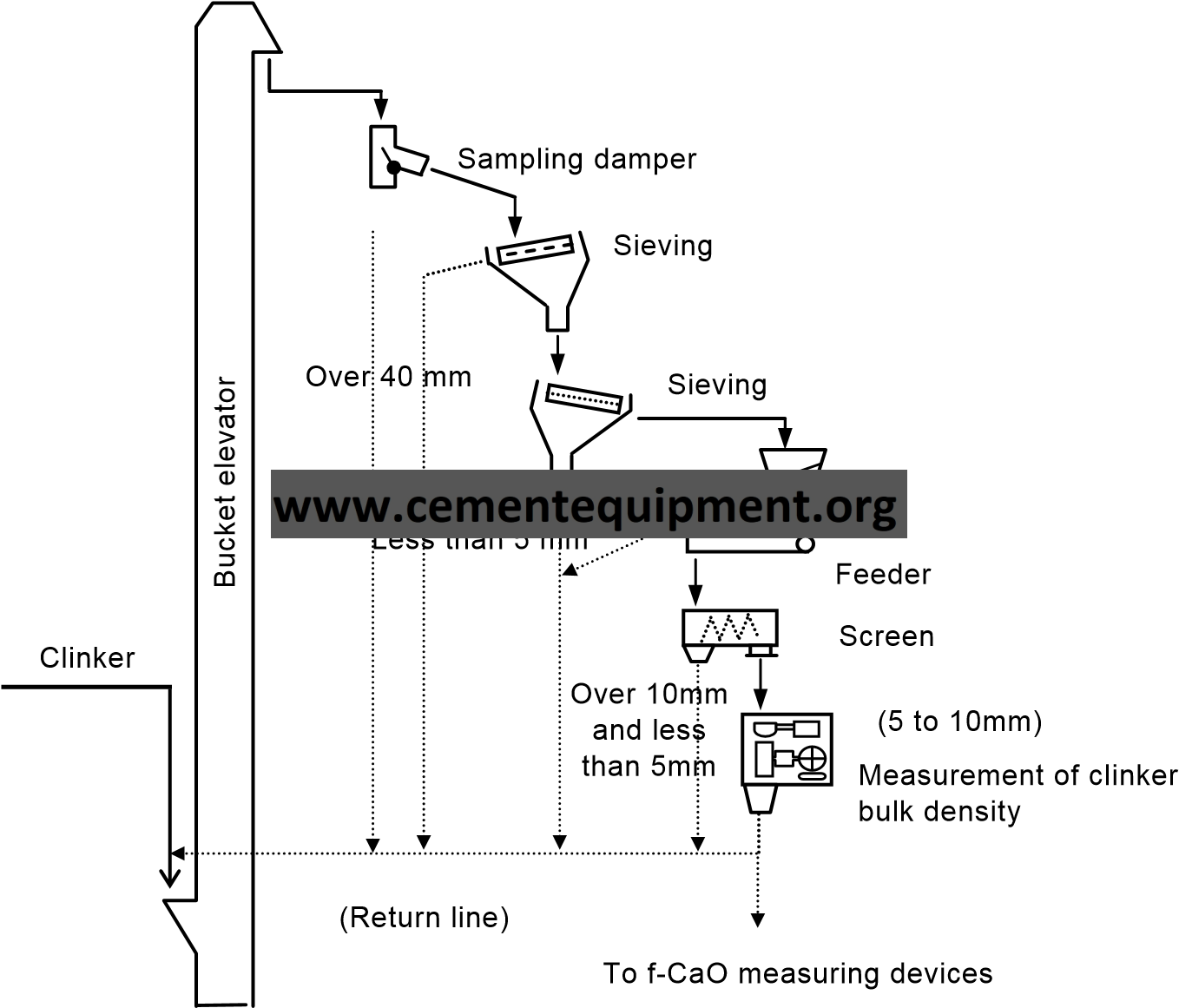
| Item | Automatic measuring device for clinker bulk density (liter-weight) | Application |
| Burning process | ||
| Background | Keeping the clinker quality constant is important factor for getting better and stable cement product. Because the value of clinker bulk density (liter-weight) shows or reflects kiln burning conditions and clinkering conditions of materials, it is widely used as an important indicating factor for kiln operation. However, there are problems such as accuracy of measured value and/or longer sampling interval since the works were done manually. Automatic sampling system and measurement are expected. | |
| Descriptions | A sampler is installed at the appropriate point of clinker transportation line. The clinker of 5 to 10mm diameter is selectively sampled with it and then pre-decided quantity of sampled clinker is automatically send to weighing vessel in order to measure the clinker bulk density. Using this measured value, kiln operator adjusts kiln operating conditions, if necessary, to keep optimum conditions. This device is usually installed and used with automatic f-CaO measurement devices and automatic clinker chemical component measurement devices. As of 2000, implementation rate is about 20% and most of the above devices are used on the on-line system.
Automatic measuring system for volume weight | |
| Results | The reliability and continuity, which is gotten by shortened sample interval, of the data of clinker bulk density are improved. And more appropriate kiln operating conditions can be gotten. | |
| Cost estimation | Main unit only: About 91 thousand US$ (excluding the sampler and sample transportation system) [1US$=¥110] | |
| Related matters | Automatic measuring device for free lime | |
| Reference | ||
97
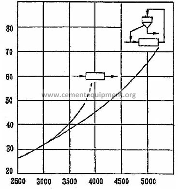
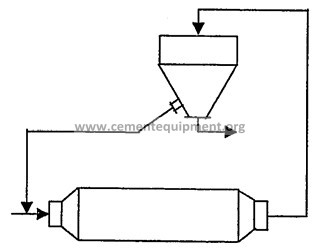
| Item | Closed-circuit grinding system | Application |
| Finishing process | ||
| Background | In the initial grinding system using a tube mill, ground materials are fed into and ground in the mill and all the output from the mill is used for products. This open-circuit grinding system required improvement both in quality and operating efficiency to solve the problem of wide grain size distribution caused by inadequate grinding and excessive grinding.
| |
| Descriptions | The closed-circuit grinding system is the open-circuit system with a large classifier. All ground materials are led into a separator and classified into refined powder (products) and coarse powder (return powder). The coarse powder is returned to the mill and ground again with newly-fed raw materials. One of the important indexes to indicate the run status of the closed-circuit grinding system is the circulation ratio that is the ratio of the amount of powder returned from the separator and the newly-fed amount. The optimum value depends on the mill conditions (ball size, liner shape, and slit size), the separator’s classification performance, and the raw material characteristics (clinker grain size and crushability). Therefore, it is important to check the optimum value for each mill.
Ground Fig.1
Open-circuit grinding system
materials
Refined powder (Product)
Tube mill
Tube mill
Coarse powder ( Returned powder )
Classifier Refined powder ( Product )
Power consumption rate of ground materials (kWh/t)
materials
Specific surface area of cement (cm2/g)
Fig.2 Closed-circuit grinding system Fig.3 Power consumption rates for open-circuit and close-circuit grinding (cement grinding)
| |
| Results |
| |
| Cost estimation | 455 million US$ (3000 kW mill) [1US$=¥110] | |
| Related matters |
| |
| Reference |
| |
 Ground
 98
| Item | Use of grinding aid | Application |
| Finishing process | ||
| Background | In general, the grinding energy efficiency of a grinder is very low. To raise the grinding efficiency, therefore, a small amount of third substance other than the grinding media and ground materials is added as a grinding aid.
| |
| Descriptions |
A tube mill generally loses its grinding efficiency remarkably at fine grinding. This is because fine particles from ground materials agglomerate and adhere to the mill liners or grinding media as coating, reducing the impulsive force of the mill. In addition, the agglomerated particles are mixed into the coarse powder in the separator and recirculated throughout the mill. There are various theories about the cause of agglomeration. The most convincing theory is that destruction in a crystal grain by alite biases the polarity of the fractured surface. A grinding aid prevents this agglomeration to improve the grinding efficiency.
| |
| Results |
| |
| Cost estimation | Diethylene glycol: 1,360 to 1,820 US$/kl [1US$=¥110]
| |
| Related matters |
| |
| Reference |
| |
99
| Item | Classification liner for the second chamber of tube mill | Application |
| Finishing process | ||
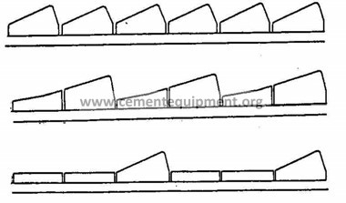
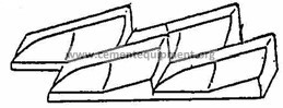
| Background | The second chamber of a finishing mill is mainly for fine grinding. Therefore, using small balls was known to be more efficient because its increases the surface area of media and strengthen the grinding effect. For the conventional mill using a liner with lifter, however, it was difficult to reduce the ball diameter drastically because the grinding efficiency is extremely lowered by reverse classification where small balls gather at the inlet of the second chamber and mediumsized balls gather at the outlet. | |
| Descriptions | To solve this reverse classification status, a classification liner was developed. The classification liner is inclined toward the inlet of the mill to make scraped balls roll in the direction. Under the influence of the rotational force (centrifugal force) of the mill, larger balls roll toward the inlet of the mill more easily (larger balls gather at the inlet of the second chamber). The development of this classification liner allowed small balls from 20 to 17 mm in diameter to be used for the second chamber and enabled efficient grinding without excessive grinding. Since this liner also improved the coarse grinding capacity at the inlet of the second chamber, the grinding performance of the entire mill may improve of the first chamber is made short and the second chamber long.
Classification liner (example)
First
chamber Second chamber
Classification liner Liner with lifter Rotating direction
A – A view
Liner with lifter (example)
Example 1
Example 2
Scraping classification liner Example 3
Fig.2 Types of classification liner | |
| Results |
| |
| Cost estimation | 682,000 US$ (3000 kW mill) [1US$=¥110] | |
| Related matters | Introduction of pre-grinder | |
| Reference | ||
 Example 4
100
| Item | Clinker flow rate regulator for tube mill | Application |
| Finishing process | ||
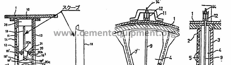
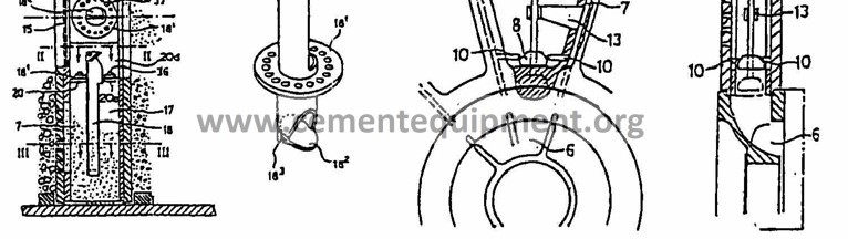
| Background | For efficient grinding by a tube mill, it is important to secure an appropriate amount of ground materials for the balls, or to maintain the powder level. The powder level of clinkers ground coarsely in the first chamber is affected by the aperture rate of the partition butt strap at the outlet and the slit size. In general, however, the powder level is set higher than the optimum value to prevent clogging in the mill. Under these conditions, large balls idle and waste energy because the powder level in the first chamber is low. Since clinkers move to the second chamber before full grinding, the fine grinding efficiency in the second chamber becomes low.
| |
| Descriptions | The powder level can be kept optimum in the first chamber by adjusting the slit size and quantity of the partition. Since fine adjustment (clinker size) is not possible because welding takes time and the crushability (coarse grinding) changes with the conditions, a clinker flow rate regulator was implemented or developed for adjustment according to the conditions. For clinker flow rate adjustment, the angle of scooping ground materials that flowed into the partition is adjusted or an on-off valve attached to the ground material discharge port is operated from outside the mill. The sound pressure level in the first chamber is the substitute characteristic for the powder level. A loss of crushing energy can be prevented by judging the sound pressure level and adjusting the flow rate regulator for full coarse grinding in the first chamber.
Fig.1 Clinker flow rate regulator Fig.2 Clinker flow rate regulator
(example) (example)
| |
| Results |
| |
| Cost estimation | About 320,000US$ (1000 kW and ∅ 3 m class mill) [1US$=¥110] | |
| Related matters |
| |
| Reference |
| |
101
| Item | Optimization of grinding media | Application |
| Finishing process | ||
| Background | To minimize the power consumption rate of a finishing tube mill, the ball size and the mixing and filling factors have been optimized. These years, however, the ball diameter is decreasing as a classification liner and a pre-grinder are adopted. In addition, the lives of such grinding media as balls and back plates are being extended by improving the material (abrasion resistance).
| |
| Descriptions |
For the optimum ball size and ball mixing, Starke, Bond, Paulsen, Bombled, and others have been proposing various calculation formulas from a long time ago. Based on these formulas and empirical rules, mixing has been determined. In recent years, the ball size is decreasing by the adoption of a classification liner and a pre-grinder. (The rate of tube mills using the smallest ball of 17 mm was about 10% in the 1979 survey by Japan Cement Association but increased to 80% in the 1991 survey.)
The filling factor of grinding media greatly affects the grinding capacity and power consumption of a mill. For cement grinding, the optimum value is in the range from 20% to 40% around 30%. To keep the filling factor of grinding media appropriate for high grinding efficiency, appropriate replenishment is necessary for compensating the abrasion of grinding media. Methods of determining media replenishment timing can be classified into five types below. Actually, however, they are used independently or in combination.
The amount of replenishment is determined by the following three elements:
These elements are used independently or in combination for determination.
Many back plates used to be made of high-magnesium cast steel and many balls used to be made of carbon steel. The recent advance of manufacturing technology is increasing both back plates and balls made of high-chromium cast iron. | |
| Results | A finishing tube mill can be operated in the optimum status.
| |
| Cost estimation |
| |
| Related matters |
| |
| Reference |
| |
102
| Item | Improvement of separator | Application |
| Finishing process | ||
| Background | With the conventional separator, which has built-in fan, such as “sturtevantseparator”, it is difficult to expand the grinding capacity by the scale-up because of lower classification efficiency. Therefore, a new high efficiency separator has been developed. | |
| Descriptions | The separators are divided into three types according to their structures. The first generation is the built-in fan type, the second is the cyclone air type, and the third is the rotor type.
Fig. 1. Cyclone air separator ⑭ dust collecting pipe to filter ⑮ return air duct
① separator part ②optional duct ext. to fit layout ③ desagglamerator
③
⑦ air + fines outlet tailings outlet ⑩⑪ reject cone support 78 air inlet rotor blades ⑧
Fig. 3. Rotating type separator Fig. 2. Rotating type | |
 ①separation chamber
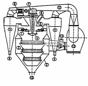
103
| Results | 1)Grinding capacity 15% to 25% (Increase) 2)Specific power consumption 10% to 20% (Reduction) |
| Cost estimation | About 4.5 million US$ for 3,000kW-mill [1US$=¥110] |
| Related matters | |
| Reference |
104
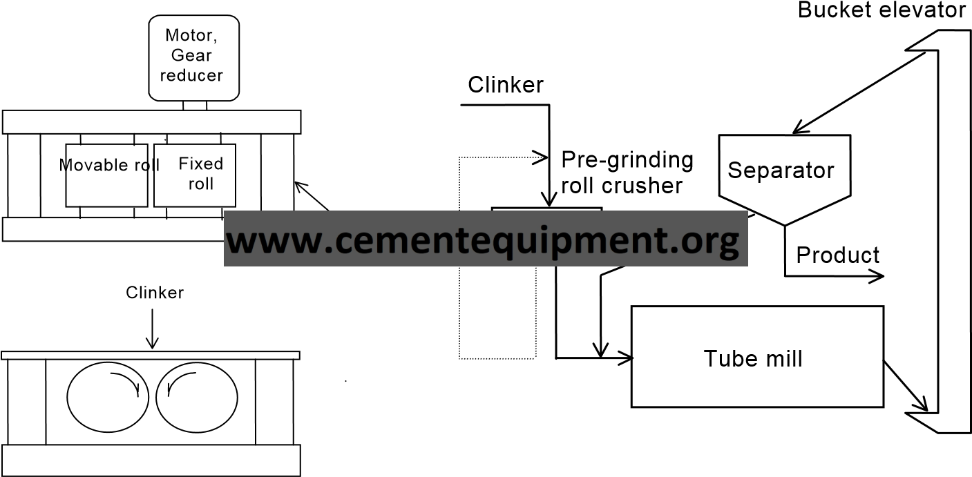
| Item | Pre-grinding of roll press system | Application |
| Finishing process | ||
| Background | To decrease the specific power consumption in finishing process or to increase the output of finish mill, pre-grinding roll crasher, which is installed in the upstream of tube mill, has been introduced since the middle of 1980s. | |
| Descriptions |
This system increases the output of finish tube mill by installing the pre-grinding roll crusher in upstream of the tube mill. By passing through the opening between two rolls (a fixed roll and a movable one), materials are crushed by high-pressure(as shown in Fig.1). High-pressure to crush the materials are generated by oil-hydraulics. Abrasion-resistant material is attached on the surface of rolls. Various kinds of system are available, and the typical one is shown in Fig.2.
Fig.1 Structure Fig. 2 Flow sheet | |
| Results |
| |
| Cost estimation | The installation cost is about 2.7 million US$ including auxiliary and construction cost, in case of 100t/h output. [1US$=¥110] | |
| Related matters | ||
| Reference |
| |
105
| Item | Pre-grinding of roller mill system | Application |
| Finishing process | ||
| Background | For the purpose of decreasing the specific electrical power consumption in the finishing process, this installs a vertical roller mill for pre-grinding of clinker in the upstream of the tube mill. The roll press system preceded as pre-grinding system, but there are many machinery troubles (flake and crack of roll surface, damage of roll shaft and bearing) for high pressure. This system was developed on the vertical roller mill which has achieve satisfactory results. It was introduced from the latter half of the 1990s, and the introduction rate in 2000 is 13%. | |
| Descriptions | This system installs a vertical roller mill (of high grinding efficiency) for a pre-grinding in the upstream of the tube mill. Clinkers are milled the turn table and 2~4 rollers. The basic structure is the same as vertical roller mills for raw materials or cement. But the roller mill for pre-grinding have no classifier and air sweep. Pre-ground clinkers were discharged outside mill. Fine particles are separated from pre-ground clinkers with vibrating screen, and they are fed to finishing tube mill. The structure (Fig.1) and the flow (Fig.2) are shown below.
separator
product
tube mill
roller mill
pre-grainding
clinker
BE
B E (gypsum)
table
roller
material feeding
Fig.1 Structure Fig.2 Flow
| |
| Results |
| |
| Cost estimation | 6.4~9.1 million US$ including cost of ancillary facilities and construction [100t/h] [1US$=¥110] | |
| Related materials | 1) Raw material pre-grinding roll crusher | |
| Reference | ||
106
| Item | Automatic run control of tube mill | Application |
| Finishing process | ||
| Background | Only several percent of the power consumption for a tube mill is used effectively and most of the energy is dissipated as heat or sound. Therefore, raising the grinding efficiency of the mill is very important for reducing the power consumption rate. To raise the efficiency, the filling factor of grinding media and materials to be crushed in the mill should be kept optimum. For this control, the power of the bucket elevator at the mill outlet used to be kept constant. This control method, however, has a disadvantage of reverse operation in case that the mill should be clogged. To compensate for this disadvantage, mill acoustic control and mill vibration control have been adopted. In addition, fuzzy control was also developed and implemented.
| |
| Descriptions | The filling factor in a mill is kept constant by the following automatic control:
The power of the elevator at the outlet of the mill is detected and the mill supply rate is adjusted to achieve the target power value. This method became popular at the earliest. This control has a disadvantage of reverse operation that the elevator power decreases and the supply amount increases when the slit clogging of the butt strap in the mill progresses. In this case, slit clogging must be monitored by the air flow rate through the mill. As of Year 2000, this control is adopted by about 70% of the finishing tube mills in Japan.
This control uses the fact that the grinding sound in a mill changes with the filling factor of ground materials in the mill. The grinding sound in the first chamber is picked up by a microphone and the supply amount is controlled by the pitch of the sound. When several mills are running adjacently at the same time, it is difficult to detect the grinding sound. This control is adopted by about 10% of the mills in Japan.
This control uses the fact that the vibration of the large metal of a mill changes with the filling factor of ground materials in the mill. It is comparatively difficult to receive the influence of adjacent mills simultaneously running. As of Year 2000, the adoption ratio in Japan is less than 10%. According to the result of a survey by the Committee, the operators are very satisfied with the control performance. Fuzzy control automatically optimizes the filling factor in a mill.
Based on the mill acoustic level, elevator power, mill differential pressure, and some more process data, fuzzy inference from present rules is conducted on changes of mill grinding conditions by a computer. Then the target value of filling factor in the mill is optimized to improve the grinding efficiency. Experiences and techniques are needed to set the rules. Once the rules have been set appropriately, efficient run is possible. As of Year 2000, this control is adopted by less than 10% of the mills in Japan. | |
| Results |
| |
| Cost estimation |
| |
| Related matters | ||
| Reference | ||
107
| Item | Vertical roller mill for cement grinding | Application |
| Finishing process | ||
| Background | In the cement grinding process, grinding system using the tube mill is widely applied for long year. Recently, especially from 1980s, grinding system using the vertical roller mill, which has effective grinding performance, is developed and applied in the cement grinding process.
| |
| Descriptions | Basic equipment structure of the vertical roller mill for cement grinding is the same as the vertical roller mill of raw material and coal grindings. The materials such as clinker and gypsum fed into the mill are ground by compression and shearing forces between the grinding table and two or four rollers, which are hydraulically loaded and controlled. Ground cement materials are sent to separator installed in mill upper position by air and classified to coarse particles and fine product. Coarse particles are returned on the grinding table to re-ground and the fine product is sent to dust collectors such as cyclone and/or bag filter.
The advantage of the vertical roller mill for cement (comparison with the tube mill)
But the introduction of a pre-grinding grinder has become mainstream in Japan, and the above-mentioned technology is spreading mainly overseas.
| |
| Results | Electrical power consumption can be reduced by 30 % (compared with the tube mills). | |
| Cost estimation | ||
| Related matters | External circulating system to vertical roller mill for cement. | |
| Reference | ||
108
| Item | External materials circulating system to cement grinding vertical mill | Application |
| Finishing process | ||
| Background | In the cement grinding process, the vertical roller mill having high grinding performance is applied especially cement grinding instead of the conventional tube mill. For further power saving, external material circulating system is adopted as same as raw material grinding process. | |
| Descriptions | As described in Page 2 of External Circulating System to Vertical Roller Mill, the external circulating system is adopted to vertical roller mill grinding process in order to reduce power consumption of mill fan. As explained in it, uncrushed large size materials jumped out from table of the mill fall through gas inlet box and collected by the external circulating system installed below the mill. And then they are retransported to fresh material feed equipment to re-send the mill. Since the uncrushed raw materials are not blown-up by the gas, transportation energy of the gas, which is generated by mill fan, extremely decreases. In the conventional roller mill system, in which the proposed external material circulation system is not installed, the power consumption by the mill fan occupies 60% of the system because high speed gas flow is blown at the around of the table to prevent falling of uncrushed larger material jumped out from the table. To the contrary, vertical roller mill having external circulating system does not require the high and large gas flow because the uncrushed materials can fall from the table to it and be re-sent to mill. As the result, gas flow rate is reduced about 30%, pressure loss is also reduced about 30% and power consumption of the mill fan reduces about 50%. The external circulation ratio (=external circulation material flow / new feed material flow) is about 50 to 100% [Conventional process] [New process]
New feed materials Vertical mill Vertical mill Gas
Stone discharge amount: To zero
Mill fan Dust collector ( c y clone, EP etc. ) Product(cement)
Mill fan Product ( cement )
External circulation system
Dust collector ( c y clone, EP etc. ) New feed materials (External circulation) | |
| Results | Specific power consumption is down about 10%.
| |
| Cost estimation | System with a grinding capacity of about 100 t/h (including the incidental facilities and construction expenses): About 730 thousand US$ [1US$=¥110] | |
| Related matters | External circulating system to vertical roller mill / Raw material process | |
| Reference |
| |
109
| Item | Automatic control of cement grain size | Application |
| Finishing process | ||
| Background | The grain size management of cement as the final product is important for maintaining stable quality and efficient run. When an finishing mill is in actual operation, however, the cement grain size changes with the passage of time under the influence of many factors. Therefore, a technology was developed and implemented to adjust the separator automatically.
| |
| Descriptions | In finish grinding, the grain size of refined powder (product) changes with the passage of time under the influence of various factors even when the running conditions are fixed. These factors are as follows:
Of these factors, a change of the clinker properties cannot be avoided to some extent as a main factor if the conditions of ground materials and facilities are considered. A means was expected to stabilize the grain size by absorbing the influence. For finish grinding, the mill run is often intermittent. The early stabilization of refined powder grain size after mill activation is another subject to solve for maintaining the stable quality and making the run efficient. Refined powder is automatically sampled and measured by a grain size distribution measuring device of the laser diffraction type. Then the separator blade or rotor rotation speed is automatically adjusted so that the measured value will match the target.
| |
| Results |
| |
| Cost estimation | About 364,000US$ [1US$=¥110] | |
| Related matters |
| |
| Reference | ||
110
| Item | High efficiency grinding of blast furnace slag | Application |
| Finishing process | ||
| Background | In the past, slag grinding is performed in a tube mill with dryer. This requires relatively higher power consumptions, and efficiency improvement in this process has become a great concern. Improvements in slag grinding efficiency was developed and implemented with existing cement manufacturing technology. | |
| Descriptions | Improvements in the grinding process to produce fine granulated blast furnace slag suitable for use in the production of blast furnace cement was achieved with pregrinding and vertical mill technologies used in cement manufacturing.
In a vertical coal mill, drying, grinding, and separating/classifying of ground material are done simultaneously. The hot air used for drying is supplied with a hot wind generator. Slag contains iron grain, which could damage the rotating table and aggravate grinding efficiency. Hence, the removal of these iron grains before commencing the grinding process, using an external circulation system with a magnetic-separator device, is crucial.
There are cases where a vertical mill is installed to the existing tube mill to enhance grinding efficiency while reducing power consumption. With the use of vertical mill, pre-grinding and cement grinding processes are performed separately. Reduction in the size of grinding media used in the tube mill is expected to improve grinding efficiency. However this would partially ruin overall efficiency improvement level.
External Circulation
Vertical Mill
Separater
Tube Mill
Bag Filter
Separater
Heat Generator
Fig. The example of the combination of tube mills and vertical mill
| |
| Results | Reduction in unit electricity consumption (Blended value 4,000cm2/g)
| |
| Cost estimation | About 7.3 million US$ including cost of supplemental facilities and construction fees [40t/h] [1US$=¥110] | |
| Related matters | Introduction of vertical raw material mill, vertical cement mill, vertical coal mill. | |
| Reference | ||
111
| Item | Automatic input facilities for waste tires | Application |
| Use of Alternative Fuels and Raw materials <AFR> | ||
| Background | Waste tires used to cause illegal disposal and other social problems because their recycling by tire manufacturers or effective use as a fuel could not catch up with the growth. The cement industries in Japan tackled this problem early and has been using waste tires as a substitute fuel since about 1980.
| |
| Descriptions |
Fig. shows a waste tire processing flow by the kiln inlet input system and the fluidized bed furnace system.
Fuel Clinker cooler Kiln Preheater calciner Aligner Fluidized bed furnace Dumper Dumper
Conveyor Waste tire Aligner Waste tire Conveyor kiln inlet input system Fluidized bed furnace system
Fig. Waste tire processing flow
| |
| Results | The effective heat from waste tires is about 25 to 29 MJ/kg (6,000 to 7,000 kcal/kg). Fossil fuels for the same amount of heat can be saved.
| |
| Cost estimation | System for 10,000 t/year: About 2.7 million US$ [1US$=¥110] | |
| Related matters | Waste tire gasification facilities | |
| Reference | ||
112
| Item | Waste tire gasification facilities | Application |
| Use of AFR | ||
| Background | Waste tires used to cause illegal disposal and other social problems because their recycling by tire manufacturers or effective use as a fuel could not catch up with the growth. The cement industry tackled this problem early and has been using waste tires as a substitute fuel since about 1980s. The conventional method of putting waste tires into a kiln as they are, however, has a quantitative limit depending on the kiln size. The gasification technology was developed to increase the capacity and improve the heat energy efficiency.
| |
| Descriptions |
Fig. shows a flow of waste tire gasification flow by a fluidized bed furnace.
Waste tire Fuel Clinker cooler Kiln Preheater calciner Fluidized bed furnace Aligner Conveyor Incombustibles
Fig. Waste tire gasification flow
| |
| Results | The heat energy from waste tires is about 25 to 29 MJ/kg (6,000 to 7,000 kcal/kg). Fossil fuels for the same amount of heat energy can be saved. | |
| Cost estimation | System for 7,000 t/year: About 1.8 million US$ [1US$=¥110] | |
| Related matters | Automatic waste tire input facilities | |
| Reference | ||
113
| Item | Waste oil and oil sludge input facilities | Application |
| Use of AFR | ||
| Background | Waste oil and oil sludge used to be left oil drums or incinerated. As the future shortage of fossil fuels is anticipated, waste oil and oil sludge utilization technologies have been developed and implemented since about 1985 in Japan, as part of energy conservation activities.
| |
| Descriptions |
Fig. shows a flow on a waste oil & oil sludge processing flow by calciner or kiln.
P
P
Flowmeter Flowmeter Waste oil & oil sludge tank Fuel Clinker cooler Kiln Preheater calciner Agitator Pump Pump Tank truck
Fig. Waste oil and oil sludge processing flow
| |
| Results | Waste oil and oil sludge vary greatly in quantity but can produce heat energy of about 10 MJ/kg (several 1,000 kcal/kg). Fossil fuels for the same amount of heat energy can be saved.
| |
| Cost estimation | Storage and processing facilities for about 10,000 kl/year: About 727 thousand US$ [1US$=¥110] | |
| Related matters | ||
| Reference |
| |
114
| Item | Waste plastic processing facilities | Application |
| Use of AFR | ||
| Background | Waste plastics generally used to be reclaimed on final disposal sites. Since it is difficult to secure final disposal sites and the shortage of fossil fuels is anticipated, waste plastic utilization technologies are being developed as part of resources and energy conservation activities.
| |
| Descriptions | The waste plastic processing technologies recently developed and now in use are mainly to shred waste plastics until almost the same combustion characteristics as the main fuels can be obtained.
Fig. shows a waste plastic processing flow.
Waste plastics Fuel Clinker cooler Kiln Preheater calciner Blower Constant weight feeder
Pneumatic conveyor
Fig. Waste plastic processing flow
| |
| Results | There are various kinds of waste plastics. The effective heat from waste plastics is about 17 to 42 MJ/kg (4,000 to 10,000 kcal/kg). Fossil fuels for the same amount of heat can be saved.
| |
| Cost estimation | System for about 10,000 t/year (including shredding facilities): About 3.6 million US$ [1US$=¥110] | |
| Related matters | ||
| Reference | ||
115
| Item | RDF processing facilities | Application |
| Use of AFR | ||
| Background | Waste used to be incinerated or reduced in volume and then reclaimed on final disposal sites. Since the emission of dioxins from incinerators and the securing of final landfill sites are posing problems, however, it is expected to reduce and recycle waste. As a method of recycling, general garbage and industrial wastes are being solidified as RDF for use as a fuel (RDF: Refuse Derived Fuel). RDF processing is effective at cement plants where incinerated ashes are available as raw materials.
| |
| Descriptions |
Blower Blower Rotary kiln RDF RDF Pulverized coal Calcination raw meal Hopper Hopper | |
| Results | RDF produces heat of 15,000 to 20,000 kJ/kg (3,500 to 4,500kcal/kg). RDF use of 10 t/d reduces coal consumption by about 5 t/d.
| |
| Cost estimation | Facilities for accepting and processing 10 t/d (excluding chlorine bypass facilities): 646 thousand US$ [1US$=¥110]
| |
| Related matters | Cyclone clogging prevention technology
| |
| Reference |
| |
116
| Item | Recycling of “pachinko machine” | Application |
| Use of AFR | ||
| Background | In Japan, it is estimated that pachinko machines (Japanese pinball machine) are produced about 2.2 million units every year and are disposed as the same. The establishment of technologies for optimum processing and recycling has been expected because illegal disposal and large field heaping posed social problems. | |
| Description s | “Pachinko,” a machine for entertainment, consists of electronic parts and also metallic, plastic, and wooden sections and is difficult to handle at a later process if merely crushed for recycling. Therefore, a comprehensive processing system is constructed for complete recycling.
This system consists of the following processes:
For solid fuel production, a volume reducer by compressive extrusion is used. Plastics molten by friction heat work as adhesives for molding and solidification. The solid fuel size is about 100 mm in diameter and 150 mm in length (about 2 kg/piece).
Flowchart
Secondary crusher
Magnetic selector V olume reducer Solid storage Primary crusher
Scrap Rawmaterials Rotary kiln Hopper scale Chip silo
| |
| Results | 1) Slid fuel: 15 kg/unit Heat: 27 MJ/kg (6,500 kcal/kg) 2) Substitute of coal fuel | |
| Cost estimation | 1) System for processing 400,000 units/year: About 8.2 million US$ [1US$=¥110] | |
| Related matters | ||
| Reference |
| |
117
| Item | Substitute raw material processing technology (Coal ashes) | Application |
| Use of AFR | ||
| Background | Coal ashes recovered by dust collectors at pulverized coal combustion boilers are discharged a lot mainly from thermal power plants throughout the nation and predicted to further increase in future. Although various processing methods are now under aggressive study, further utilization at cement plans is expected because it is difficult to process large quantities and to secure disposal sites.
| |
| Descriptions |
Electrostatic
Iron source Silica Exhaust Raw material mill Clay Limestone Precipitator Raw meal silo Blower Coal ashes ( ) dry Coal ashes wet) ( Fan | |
| Results |
| |
| Cost estimation | 2000 ton-silo and input facillities: 2.7 to 3.2 million US$ [1US$=¥110]
| |
| Related matters |
| |
| Reference |
| |
118
| Item | Substitute raw material processing technology (Slag) | Application |
| Use of AFR | ||
| Background | At the process of manufacturing iron & steel or nonferrous metals, a product of reaction between impurties in raw materials and limestone added as an agent to eliminate sulfur and impurities is discharged as a molten oxide. The oxide is cooled and crushed. This is called slag and discharged a lot throughout the nation. From a long time ago, slag has been used as cement raw materials and also road construction materials.
| |
| Descriptions | As a representative slag having a hydraulic property, blast furnace slag is ground to fine particles, mixed with cement, and used widely as blast furnace cement. On the other hand, various kinds of slag lower in quality are used as raw materials for cement.
Electrostatic Fan precipitator
Iron source Silica Exhaust Raw material mill Clay Limestone Raw meal silo Slag
| |
| Results |
| |
| Cost estimation |
| |
| Related matters |
| |
| Reference |
| |
119
| Item | Substitute raw material processing technology (Sludge) | Application |
| Use of AFR | ||
| Background | A large amount of construction sludge generated throughout the nation used to be reclaimed for final disposal. With the decrease of land for reclamation, illegal disposal increased. Since it is also difficult to secure disposal sites, an effective utilization technolgy is expected.
| |
| Descriptions |
| |
| Results |
| |
| Cost estimation | The use of existing facilities cuts costs. Unchoking measures : hundreds of thousands to million of US$
| |
| Related matters | Automation of raw material mixing control
| |
| Reference |
| |
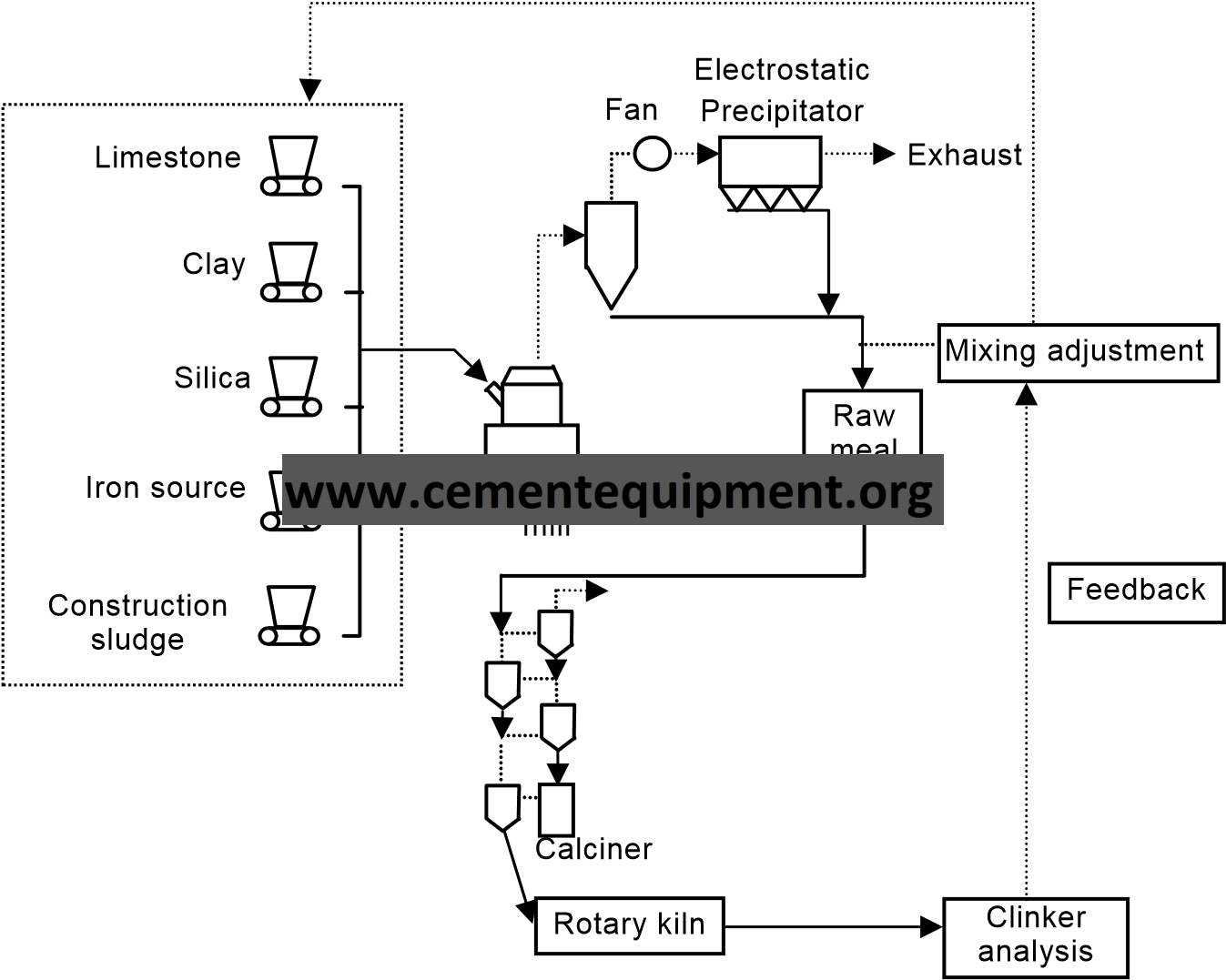
120
| Item | Substitute raw material processing technology (Sewage sludge) | Application |
| Use of AFR | ||
| Background | Sewage sludge from local governments throughout the nation used to be disposed of mainly by reclamation or sea dumping. The sea dumping of industrial wastes is becoming a social problem and their effective utilization is expected.
| |
| Descriptions | Sludge from sewage plants is brought to cement plants in the form of dehydrated cake (water content: about 80%) or incinerated ashes.
Electrostatic
Exhaust Precipitator Raw material silo Fan Rotary kiln Sewage sludge Sewage sludge Raw material mill Raw material dryer Mixed raw materials Sewage sludge Calciner | |
| Results | 1) The consumption of natural resources is reduced. 2) The service life of final disposal site is extended. | |
| Cost estimation | Pressure feed pump into the furnace : 1.8 to 3.6 million US$ [1US$=¥110] | |
| Related matters | Automation of raw material mixing control
| |
| Reference |
| |
121
| Item | Waste acid and alkali processing facilities | Application | |
| Use of AFR | |||
| Background | The general method of disposing of waste acids and alkalis in large quantities used to be sea dumping after neutralization. Since sea dumping is now prohibited by the London Dumping Convention, a safe and effective processing method is expected.
| ||
| Descriptions |
Dried raw
Electrostatic Precipitator Preheater exhaust gas Non-processed raw materials Industrial water Outlet gas temperature Rotary dryer Waste alkali reservoir tank P P materials | ||
| Results | The consumption of water resources and the energy for waste water treatment can be reduced.
| ||
| Cost estimation | Receiving and spray facilities : several hundreds of thousand US$
| ||
| Related matters | Chlorine bypass system
| ||
| Reference |
| ||
122
| Item | Power generation utilizing waste heat | Application |
| Waste heat recovery | ||
| Background | The temperature of the exhaust from the suspension preheater (SP) or the new suspension preheater (NSP) is about 400℃. The exhaust has the surplus heat even if it is used to dry the raw materials. Also the surplus heat comes from the clinker cooler. It was desired to utilize the surplus heat (= waste heat) for energy saving. | |
| Descriptions | The power generator by the waste heat has been installed with the progress of technologies on the waste heat generation and after the appearance of large-scale kilns. The popular system is as follows. The boilers are installed at the outlet of suspension preheater or clinker cooler. The low pressure steam is made in boiler by waste heat recovery. And, the electrical power is generated with the steam turbine. The amount of generated electrical power per 1 ton of clinker is 35-40kW on an average. In the case of kiln of 5000 ton per 1 day, the 8000kW of electrical power are generated. In the typical NSP kiln equipped with power station by waste heat, the energy utilization efficiency on the burning process reaches about 80% and the temperature of the exhaust after using of drying raw materials is about 100℃.
| |
| Results | The power station by waste heat can generate electrical power of about 35 to 40 kW per 1 ton of clinker. | |
| Cost estimation | About 27.3 million US$ including cost of supplemental facilities [1US$=¥110] | |
| Related materials | The recycled utilization of the exhaust gas of the clinker cooler | |
| Reference | ||
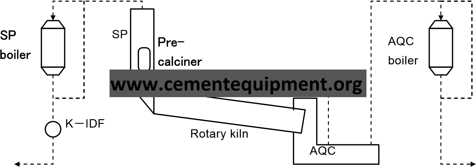
123
| Item | Recirculation of exhaust air from cooler | Application |
| Waste heat recovery | ||
| Background | A clinker cooler exhausts air of about 200 to 300°C. This exhaust air used to be released into the atmosphere as it is. Installing a waste heat boiler is an effective means of using potential heat from the exhaust air. However, means of thorough energy conservation are expected.
| |
| Descriptions | Regarding a cooler, it is most important to improve the recovery of heat to the secondary air for combustion. From the viewpoint of an whole kiln, it is also important to thoroughly make an effective use of residual heat not having a very great value as heat.
From air discharged out of a cooler, dust is removed by an electrostatic precipitator or bag filter. Then the low-temperature air is circulated again to cool clinkers. This cooler exhaust recirculation technology minimizes heat discharge out of the system by using potential heat effectively.
Example : With waste heat boiler
EP
Boiler
Secondary
air
Tertiary
air
Clinker
Cool
air
Clinker
: Fan Recirculation
| |
| Results | 1) (a): Waste heat recovery rate up about 10% (50% of exhaust air circulated) 2) (b): Heat consumption rate down about 25 kJ/kg-cl (6 kcal/kg)
| |
| Cost estimation | 0.9 to 1.4 million US$ [1US$=¥110]
| |
| Related matters | Power generation from waste heat
| |
| Reference |
| |
124
| Item | Reduction of cyclone pressure loss | Application |
| Common | ||
| Background | The power consumption rate of an exhaust fan at a preheater is affected by cyclone pressure loss. If the negative pressure is great, leakage air increases. Therefore, a cyclone of low pressure loss was expected.
| |
| Descriptions | A cyclone pressure loss is reduced by the following technologies:
The inlet shape of an ordinary cyclone is devised to reduce the inlet wind velocity. This exhibits the gravity sedimentation effect and reduces the pressure loss while maintaining the dust collection efficiency. Such special types as axial and horizontal are also available.
A vane is installed where the inlet gas flow collides against the swirling gas flow. This prevents the inlet gas flow from diminishing and assists the formation of a downward flow in the cyclone to reduce the pressure loss while maintaining the dust collection efficiency.
By considering the applicable cyclone position, the internal cylinder and the length of the rectifier plate in the cylinder are adjusted. According to a report, the pressure loss at inversion can also be reduced greatly by installing a special device at the lower part of the internal cylinder.
Main dust outlet 特殊形状サイクロン Special cyclone Guide vaneガイドベーン dust
Gas
outlet
Gas
inlet
Guide
Vane
| |
| Results |
| |
| Cost estimation |
| |
| Related matters | Five-stage preheater
| |
| Reference |
| |
125
| Item | Reduction of bag filter pressure loss | Application |
| Common | ||
| Background | The conventional bag filter has disadvantages that the pressure loss and power consumption rate increase with the passage of time as the filter cloth deteriorates and that the filter cloth is damaged in a short period. Therefore, a filter cloth of a low pressure loss was expected to support stable run for a long period.
| |
| Descriptions | The conventional bag filter uses a felt cloth for filtration. This cloth is for three-dimensional filtration where the primary dust layer formed on the surface of the cloth filters later dust. Therefore, dust penetrates into the material and increases the pressure loss with the passage of time. To solve this disadvantage, a new filter cloth was developed by laminating a fine multipore film on the surface of a felt substrate. Since this is surface filtration by micropores, dust comes off easily from the filter cloth. By shaking off dust appropriately, the pressure loss of the filter cloth can be kept almost constant. Compared with the felt filter cloth, the filter cloth has a slightly great pressure cloth at the beginning of use but is almost free of influence by residual dust. Therefore, the new filter cloth can be used stably for a long time with a low pressure loss.
濾布の寿命 3次元濾過タイプ
濾布の圧力損失
破損
面濾過タイプ
Pressure loss of filter cloth
3 D filtration type
Life of filter cloth
Surface filtration type
Damage
Life of filter cloth and pressure loss
| |
| Results |
| |
| Cost estimation | 150 mm dia. × 3,500 mm long: About 450US$ [1US$=¥110]
| |
| Related matters |
| |
| Reference |
| |
126
| Item | Fan rotation control | Application | |||||||||||||||
| Common | |||||||||||||||||
| Background | At the cement manufacturing process, many large fans are used. Power consumption by these fans is regulated by throttle control and rotation speed control. Rotation speed control is superior to throttle control in energy saving performance. Rotation speed control can be classified into mechanical control, like fluid joint and secondary resistance control, and into electric control, like Scherbius control and inverter control.
| ||||||||||||||||
| Descriptions | Depending on the motor types, there are several methods of controlling the fan rotation speed by varying the rotation speed of the motor that drives the fan. The representative static Scherbius control is explained here. A wound-rotor induction motor for a large fan, like a preheater ventilation fan, used to be controlled by secondary resistance control that changes a rotation speed with a variable resistor on the secondary side. The typical variable resistor is liquid resistor. This control method is more economical than any other method because the structure is simple. However, the method also has disadvantages that the rotation speed changes by steps and that the efficiency is low, compared with other methods, because the secondary resistance loss becomes greater at a low speed. Low efficiency attributable to the secondary resistance loss did not matter in the past production for maximum output but began to appear a problem during the long-term suppressed production. Replacing this, the static Scherbius control was aggressively adopted as a control method of high efficiency. The static Scherbius control changes the rotation speed by applying a voltage to the secondary circuit. Of the secondary power, the secondary slip power is converted into AC by an inverter for the primary power (power supply). Therefore, this control method features higher efficiency than secondary resistance control and a smaller loss attributable to a decrease of power factor at a low speed. However, the cost is higher.
i Pi . Pb(電力)(Power)
. PM . . P P R I.M. . IM Transformer PoPo DC Inverter Rectifier (熱損失)L (Thermal loss) AC 二次抵抗制御 Static Scherbius control 静止セルビウス方式 Secondary resistance control | ||||||||||||||||
| Results |
| ||||||||||||||||
| Cost estimation | 270 thousand US$ (Motor ratings: 2,350 kW, 6 P, 3,300 V, and 60 Hz) [1US$=¥110] | ||||||||||||||||
| Related matters |
| ||||||||||||||||
| Reference |
| ||||||||||||||||
127
| Item | Fan impeller cutting | Application | |||||||||||||||
| Common | |||||||||||||||||
| Background | At the cement manufacturing process, many fans are used to process combustion gas and air. These fans have necessary capacities for their positions. However, some fans may have excess margins which may increase as process changes. Since these margins waste power, fan impeller cutting is executed. | ||||||||||||||||
| Descriptions | Fan impeller (runner) cutting is generally executed as shown below.
Cut
2620
Φ 2380
When the rotation speed is the same, the wind rate is proportional to the ratio of impeller diameter. The pressure is proportional to the second power of the ratio and the electric power is proportional to the third power of the ratio. Therefore, the energy saving effect is great. The limit of impeller cutting is generally said to be about 20% of the original diameter. Excess cutting may
When reducing the wind rate more 20% or more, the impeller should be replaced.
| ||||||||||||||||
| Results | Effect on 1700 kW kiln IDF (same wind rate)
| ||||||||||||||||
| Cost estimation | Fan impeller replacement: 0.5 million US$ [1US$=¥110] (Impeller cutting, including the main and side plates) Vane cutting only: 27 thousand US$ [1US$=¥110] | ||||||||||||||||
| Related matters |
| ||||||||||||||||
| Reference |
| ||||||||||||||||
128
| Item | Material sealing | Application |
| Common | ||
| Background | Undesired air leakage, which is made by huge pressure difference, especially occurred at material feed area of vertical mill, makes many operational troubles such as un desired increasing of gas flow, reduction of mill grinding capacity by poor drying performance caused by decreasing of gas temperature with cold leak air and undesired increasing of power consumption of mill fan caused by increasing of gas flow by leak air. Air leakage can be reduced by using flap dampers of multiple stage or screw feeders having multiple screw shafts.
| |
| Descriptions | The figures below show the 3-stage FD method. The 3-stage FD consists of three flaps. Flaps sequentially open from top, middle and lower stage. When one stage is open, the remaining other stages are fully closed and their spaces are fully filled by materials. This makes strong seal for leakages.
Raw material FLAP OPERATION
CLOSE UNDER OPENING OPERATION UNDER CLOSING OPERATION 1 -12-1 -1 FLAP 1
1-22-2 1-2 FLAP 1-3 FLAP 1 -32-3 2-1 FLAP 2-2 FLAP 2-3 FLAP
In the double screw method, Raw materials are fed and discharged to vertical mill by the filled up conditions made by double parallel shaft screw rotating inward. This mechanism makes effective seal conditions.
Raw materials M | |
| Results | The 3-stage FD method reduced 30,000 m3 N/h or 30% of 100,000 m3 N/h leakage from 330,000 m3N/h gas flow at the outlet of a vertical raw material mill. This corresponds to a reduction of 150 kW or 4% in IDF power. | |
| Cost estimation | 3-stage FD system: 180 thousand US$ [1US$=¥110] | |
| Related matters | ||
| Reference | ||
129