Contents
To download the below and all other Useful Books and calculations Excel sheets please click here
To download the below and all other Useful Books and calculations Excel sheets please click here
Cement plant Maintenance
Objectives for this Lecture :
Enhance understanding of:
-The key success factors in the Maintenance Process
-The impact of Maintenance on Manufacturing Performance
-How you can influence the Performance of Maintenance
Definition of Maintenance
- To maintain and restore the desired condition
- To define and assess the actual condition of technical assets (Equipment & Components, Buildings, Spare Parts…)
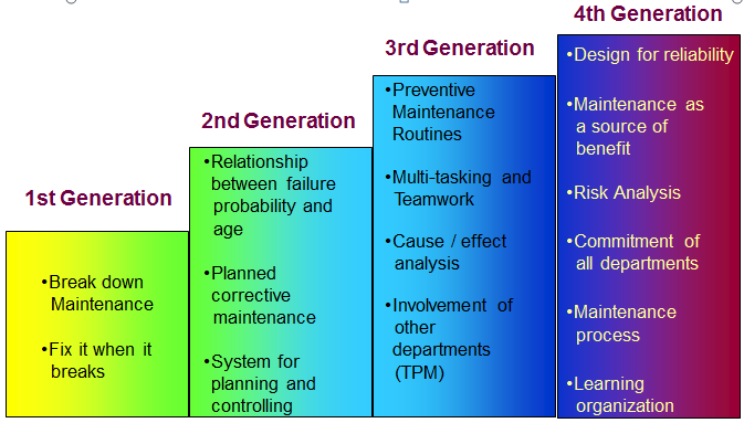
Evolution of Maintenance in Industry
Performance of Maintenance
- Maintenance Cost
- Equipment Performance
OEE and its components

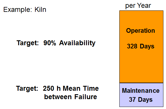
Importance of Availability & MTBF
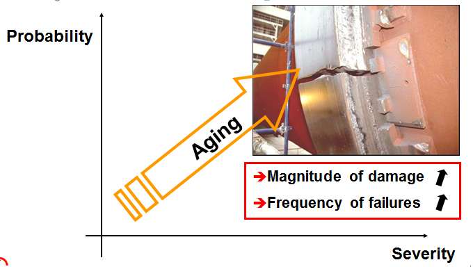
What is changing with Age?
The solution is not just more maintenance – It requires…
- Maintenance Organization with defined key positions
- High level of experience, competences and skills
- Clear defined limits for operation – Standard operating procedures
- Correct design and quality of equipment to assure reliability
- Equipment replacement strategy – when to maintain, when to replace
- Maintain equipment condition fit for operation – maintain reliability
- Proactive, structured management system – Continuous Improvement
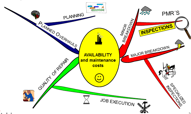
Introduction: Main Factors Influencing OEE
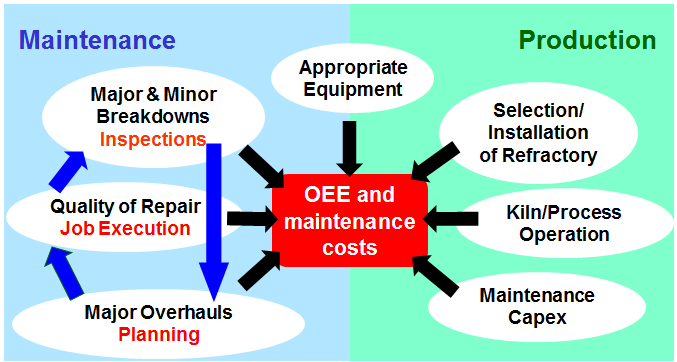
Inspections
Learn about key success factors of Inspections, so you can optimize Equipment Downtime and therefore increase OEE – have a positive effect on maintenance cost
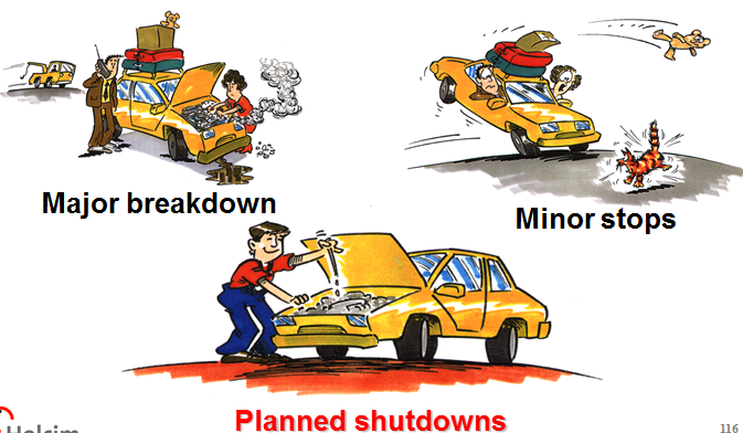
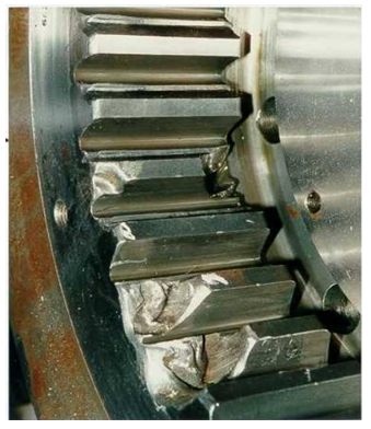
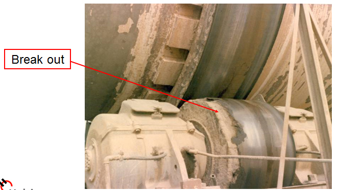
Major breakdowns
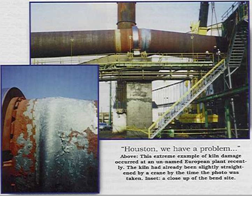
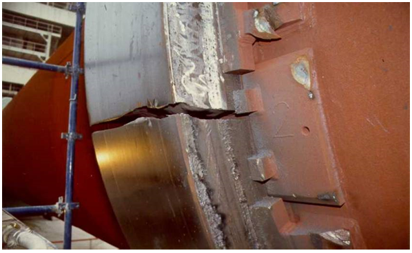
Major breakdowns – Can we avoid them?
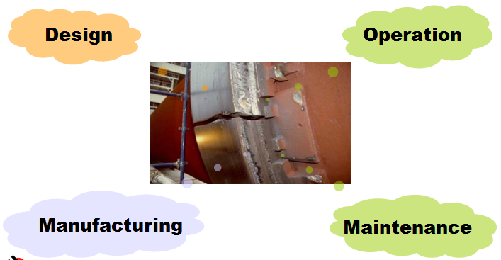
Design
Manufacturing
Quality Control of Equipment
We look for…
- without defects
- small defects
- medium defects
- large defects
- rejected parts
QCE (without defects)
QCE (small defects)
QCE (medium defects)
QCE (large defects)
QCE (rejected parts)
Operation
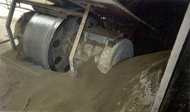
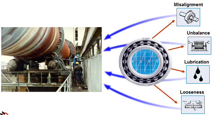
Maintenance (Equipment Monitoring Solution)
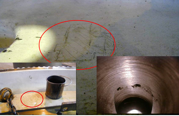
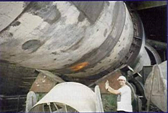
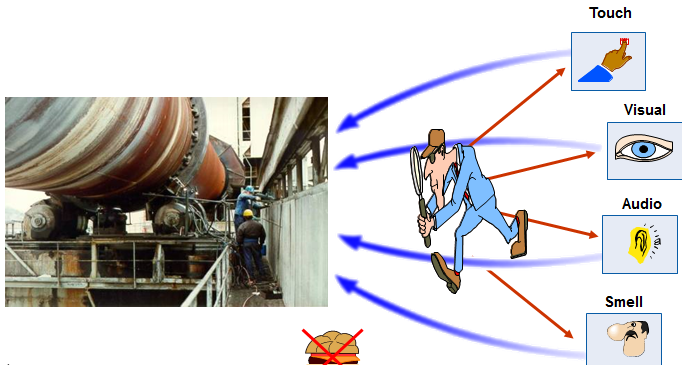
Walk-by inspections
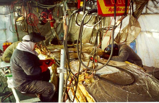
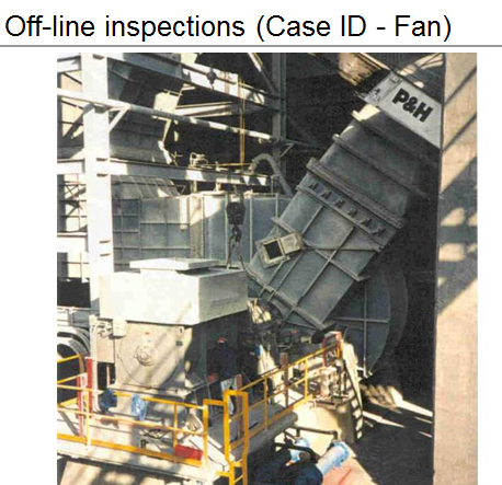
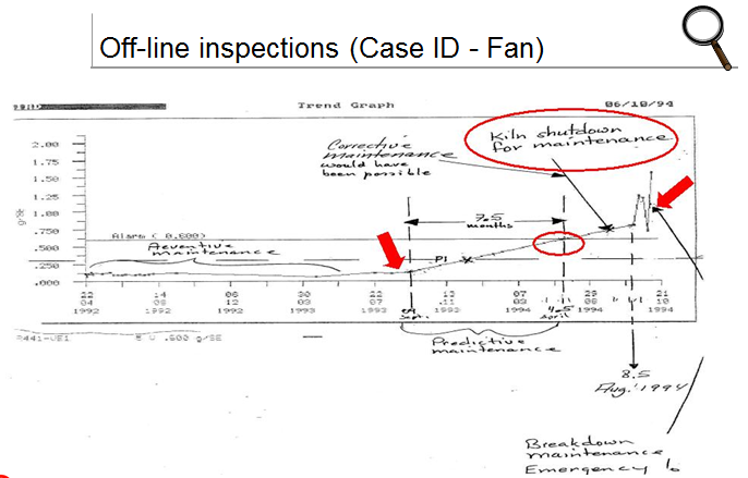
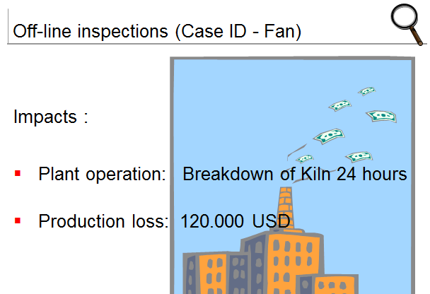
Off-line inspections
On-line Monitoring

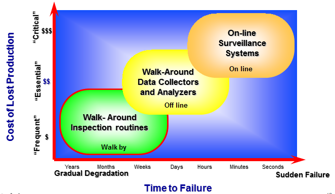
Level of Inspections / Monitoring
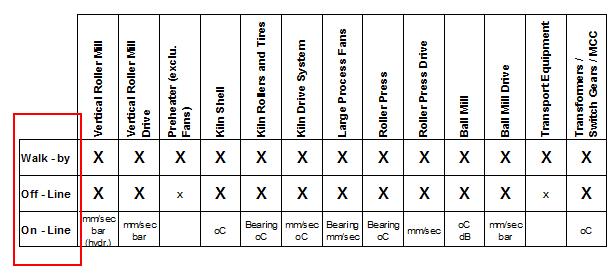
(Equipment Monitoring Solution)

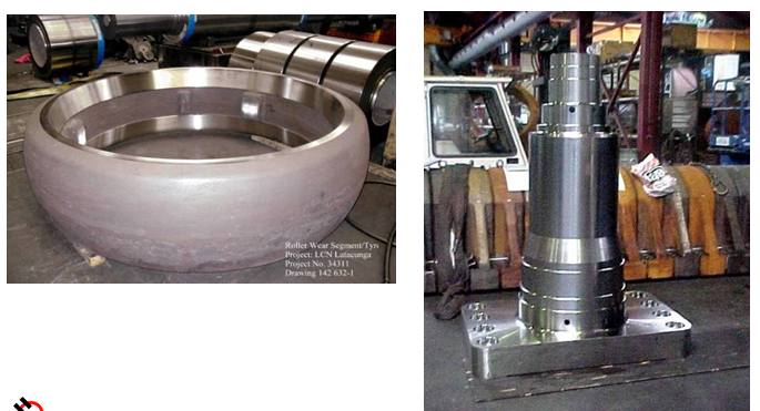
Causes of roller misalignment
- Incorrect adjustment
- Misalignment of the kiln
- Wear on rollers, tires or bearing
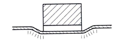
- Setting of the foundation
- Temperature effects
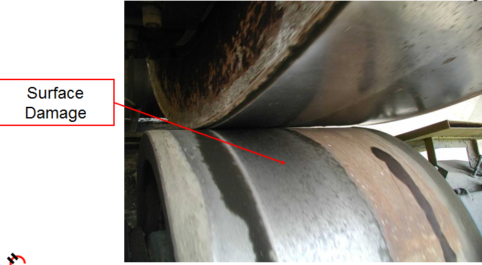
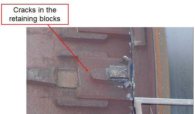
Consequences of roller misalignment
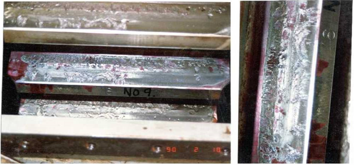
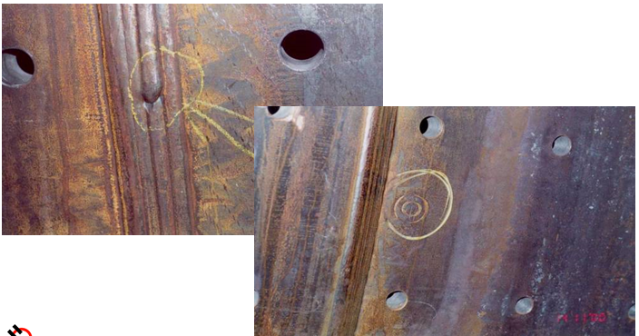
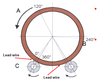
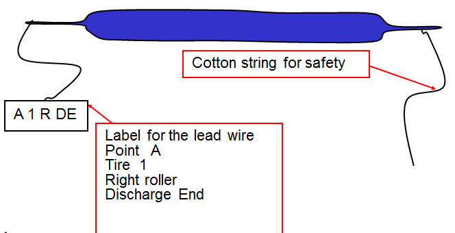
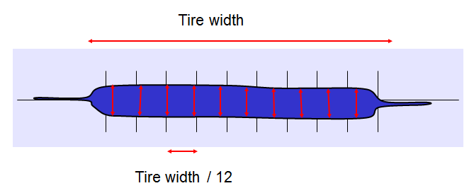
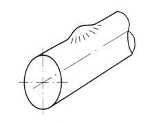
Lead Wire Method
- Use lead wire of 2 to 4 mm in diameter, oil it and pass it between the Tyre and Roller in A,B,C positions
- On condition that the surface of the Tyre and the Roller are straight and undamaged, one will received the lead wire stripes of distinguishing stress concentration
Lead Wire Method: Standard Value
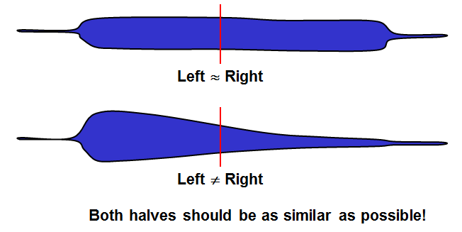
Parallel
Parallel adjusted rollers show an equally distributed contact stress
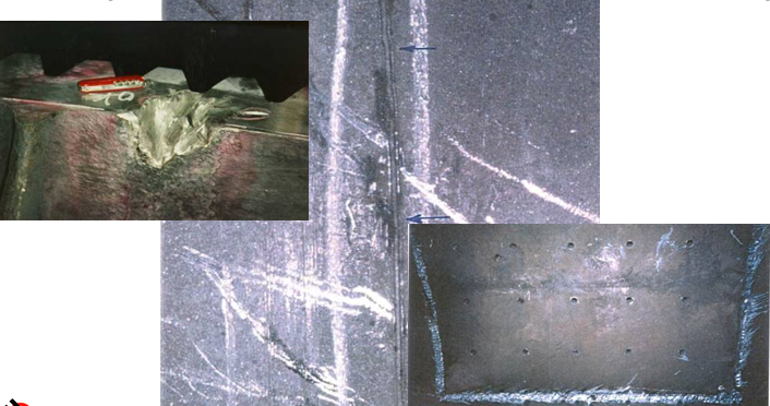
Horizontally cut
Rollers which are cut in the horizontal plane show a stress concentration in the middle of the contact width
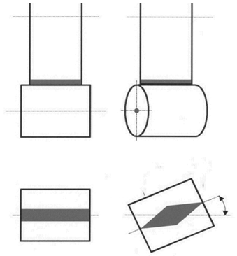
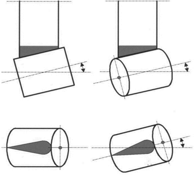
Horizontally and Vertical Cut
Rollers which are cut in the horizontal and vertical plane show a stress concentration at one end of the contact width
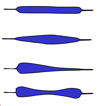
Lead Wire Method. Results evaluation
- Roller parallel to the tire, pressure equal throughout the width
- Roller slightly cut, pressure in the middle, check wear or inclination
- Roller cutting pronounced pressure in one end
- Roller surface is not straight and requires machining
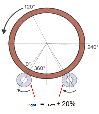
- The result on the 3 positions A,B, C should be identical.
- Difference are indication of a kiln crank or a wobbling tire
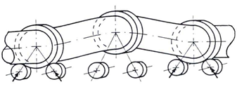
How to plot the results
Lead Wire Method: Standard Value
- Both side rollers should have results in the same range (+/- 20%)
- So that the kiln is equally supported on both roller
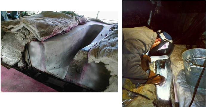
Shell test
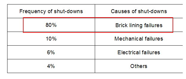
Kiln downtime causes
The following is a typical breakdown of the downtime causes for a kiln
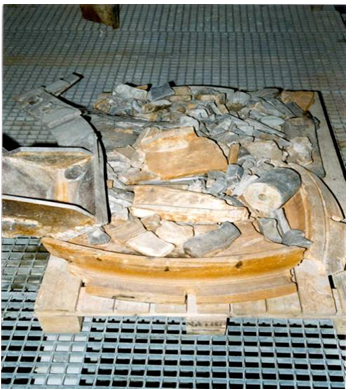
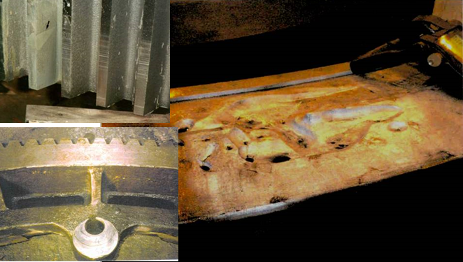
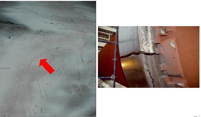
Radial deformation and its effect
Creep / Relative movement (loose tires)
To avoid permanent constriction of shell due to thermal expansion the shell and tire have different diameter
Plastic (permanent) deformation
Shell constriction (restricted expansion)
Buckling (local overheating)
Crankshaft (excessive circunferential temp. difference)
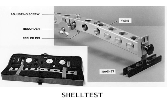
why we do Shell test
- The shelltest device measures the kiln shell radial elastic deformation.
- One of the main results of this test is the ‘Ovality’ value, which is compared against the recommended value.
- In addition, thanks to the graphical representation of the deformed kiln cross section, information on:
-Tire clearance
-Tire stiffness
-Roller adjustment (in some cases)
-Kiln deformation (crankshaft)
can be obtained
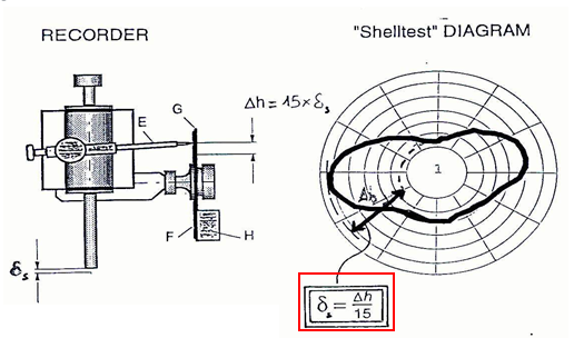
Shelltest device
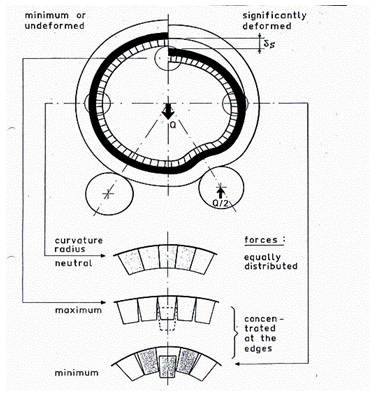
Measurement principle
- The kiln cross section is rather elliptical
- If the two axis (a and b) are known, then ovality can be calculated
- Or, with the magnitude of the radial deformation ds
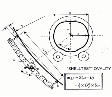
- Through the Shelltest diagram, ds can be obtained, as the maximum difference between sector height, magnified by a factor of 15.
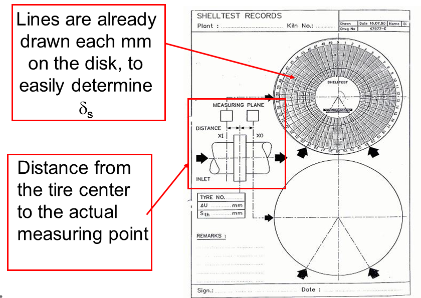
How to measure
- Ovality has to be measured as close as possible to the tire, on both sides of it (feed and discharge side).
-Watch out with the heat shields, in case they obstruct the passage of the device!
- As in the lead wire test, on each side of the tire, three measurements have to be made (120° displacement).
-Each set of points (A, B and C) must be collinear and marked in a permanent way.
-A single diagram disk can be used for the three measurements (adjusting screw position has to be modified, to avoid overwriting curves).
-After each measurement, identify the resulting curve (A, B or C) . If the curve is not easily readable, remark it with a pencil).
Form to be filled in for each diagram disk
How to measure- Tips and tricks
- The disk face must always point at the same side of the kiln (whether feed or discharge end).
-This reference has to be kept in mind when looking at the curves
- Be sure that the disk cannot rotate on its own (fasten it with the small hole, which indicates as well the apex point of the shell)
- After attaching the device to the shell, do not stand right underneath! (it may drop on top of your head)
- Let the device make a whole revolution, before pushing the pencil in; check that the pencil touches the disk
- After each measurement, cool down the magnetic base with water (otherwise, it will lose its strenght)
- Wear personal protective equipment, including gloves.
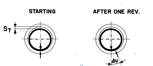
- Do not forget to measure relative movement (creep) on each tire.
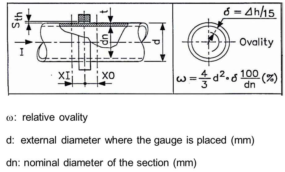
Calculating ovality
It can be done graphically, or using the formula
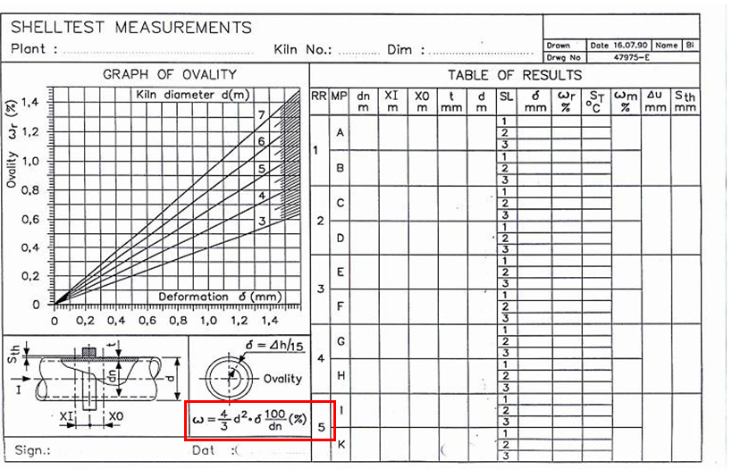
- The graphic method is much easier
- As the relative ovality limit values are given as a range, it is not crucial to obtain a result with two decimal places.
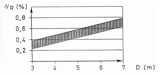
Evaluation of results-Ovality value
- The following graph shows the adequate relative ovality ranges, according to the kiln diameter
- If the value falls within this range or below, no corrective action is required (tire shimming)
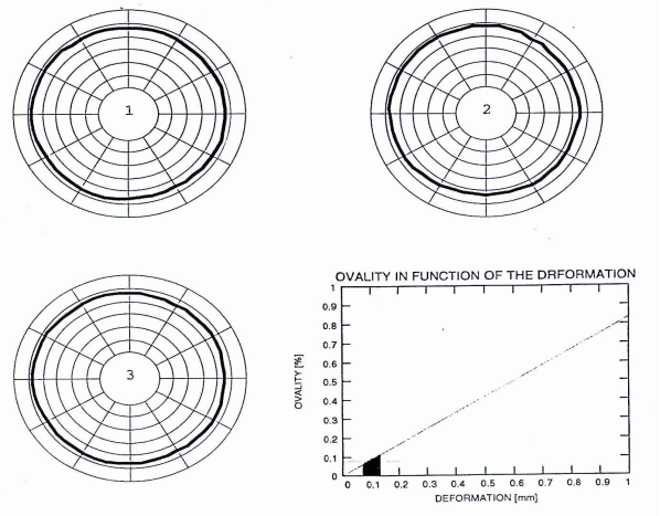
Case #1:
- Low ovality
- low clearance (no flattening of the shell at the top)
- no deformation at supporting areas
Result: Ideal situation – no actions rather than periodic monitoring needed
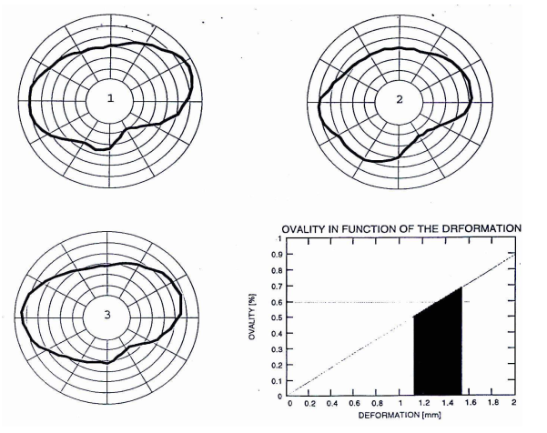
Case #2:
- High ovality
- excessive clearance (flattening of the shell at the top)
- deformation at supporting areas (soft tire)
Result: Roller adjustment required, as well as clearance decrease (tire shimming)
What is the issue and what will we do?