Contents
To download the below and all other Useful Books and calculations Excel sheets please click here
To download the below and all other Useful Books and calculations Excel sheets please click here
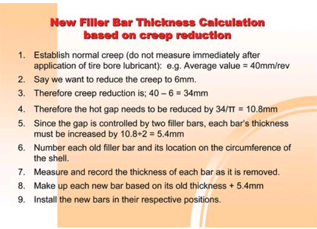
New Filler Bar Thickness calculation based on Creep Reduction
This procedure is usually only required with refractory lined units. Non refractory lined units can
still use these guidelines but make the fit tight so that the creep is as close to zero as possible. The steps in principle are outline here. The actual sequence of events will be determined by how the old filler bars are mounted; specifically if they are welded under the tire, which may mean partially or completely relocating the tire.
In any case the work should always be carried out in the upper area of the shell, usually involving only three or four bars between incremental shell rotations. Removal, replacement and welding should only be done in the down hand position, never on the vertical or overhead. If it was necessary to push the tire completely off the pads to get the old bars out, necessitating lifting the shell, the tire will be put back in place by supporting it with temporarily placed filler bars in order to allow rotation to fit the new bars while working in the upper area only.
Using any other technique, will take longer and risk lower quality of workmanship.
OK, I agree, there is no proactical way that a new set of shell pads (filler bars) can be made to thicknesses other than standard plate sizes. So there is more to this procedure than outlined here but at least this is the theoretical start.
Posted by Walter Gebhart
Thx