Contents
To download the below and all other Useful Books and calculations Excel sheets please click here
To download the below and all other Useful Books and calculations Excel sheets please click here
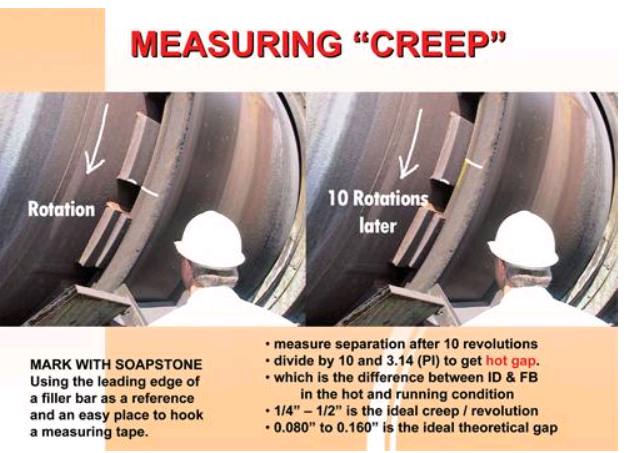
“CREEP” MEASUREMENT ON MIGRATING TIRES (Refractory Lined Units)
The riding rings provide substantial strength to the shell by maintaining shell roundness. Because the shell naturally flattens out at the 12 o’clock position the riding ring system must maintain shell integrity by minimizing flex.
To accommodate any difference in the expansion rate of the shell and the tire, there is a difference in the size of the shell’s outside diameter (OD) and the tire’s inside diameter (ID), the tire having a larger diameter. Because of this difference the tire naturally wants to creep, or migrate at a slower rotational speed than the shell. The shell is actually rotating at one speed and the tire is lagging behind just a little.
By making a mark with a soapstone from the side face of the tire to the surface of a filler bar, or along a stop block, it is possible to witness the marks slowly separate during each rotation. This separation is a direct measurement of the fit between the shell OD and the riding ring ID.
Worn filler bars, or supports, allow excess gap at the shell’s 12 o’clock position, thus allowing excessive flexing of the shell plate as the drum rotates. This reduces the shell support provided by the riding ring, accelerates and compounds support pad wear, and leads to fatigue cracks in the welds of the mounting system and can eventually lead to shell cracks. The biggest impact of course is on refractory. If there is no refractory the tires should be fixed.
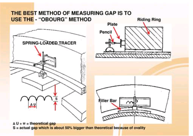
When we go to the top of the kiln and measure the actual gap we find that it is larger than the
difference in circumferences (Tire bore circumference less shell filler bars circumference) divided by ? . The reason for this is ovality, meaning the shell sags across the top. Another way to think of this is that the shell and tire are not perfect eccentric circles. If they where then the gap would be equal to the creep/ ?. Even this assumes that the creep is the result of true rolling action with no slip or hang-up. The Obourg device shows us the complete story. It shows us the relationship between slip, gap and the effects of ovality.
The amplitude “s” of the resulting plot is the actual gap. The period “? U” is the prevailing creep.
? U / s ? ? but something more like 2 to 2.5. This ovality ratio varies from kiln to kiln and tire to tire.
This may seem like a very academic issue but it has great significance when it comes to calculating the expected filler bar thickness when reducing the gap to correct ovality is necessary. Although this is an excellent diagnostic tool its use is often limited by the presence of thrust rollers and high speed kilns.
Posted by Walter Gebhart
I need information about kil maintenence
Awesome
Thanks