Contents
click here to Download the Most Important 13 Books in Cement Industry
click here to Download the Most Important 13 Books in Cement Industry
EVERYTHING YOU NEED TO KNOW ABOUT OPERATION AND CONTROL OF CLINKER COOLER
It is extremely important for the operator to master cooler controls as well as other control functions of the rotary kiln system, because the cooler itself performs an integral part of the clinker-burning process. Cooler conditions influence the burning process in the kiln and consequently, the quality of the clinker. There are many instances where cooler operating problems can lead a perfectly stable kiln into a severely upset condition with possible damage to the equipment.
With the introduction of large-sized rotary kilns having production capacities in excess of 1500 tons per day, traveling grate cooler.; have become a problem in some plants. Unexpectedly, widespread complaints began as cooler components burned up and entire coolers had to be repaired at alarming rates. These problems were not only experienced in North America but were also encountered throughout the world wherever large rotary kilns had been placed into service. Regrettably, a final solution to the problem has not yet been found, and in some cement plants frequent cooler failures due to overheating still persist. On the other hand, major modifications and improvements in the design of cooler equipment in the past few years have lessened the problems to a large extent and indications are that coolers can now be made 19 operate in a satisfactory manner. Also, not all cooler failures are caused by design of the cooler itself, for inexperience and laxness on the part of operators has contributed to the problem. The detailed description of cooler control functions in this chapter can give the operator the information he needs to help lessen the frequency of cooler failures.
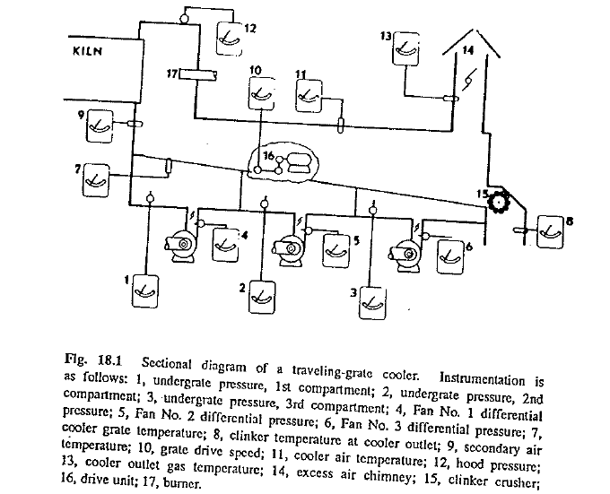
Fig. 18.1 shows a schematic layout of cooler controls to familiarize the leader with the various terms used. It does not represent any particular nake of cooler, but shows the components and principles involved in cooler construction and operation.
CRITICAL VARIABLES IN COOLER CONTROL
The kiln operator must operate the cooler in such a manner as to meet e following objectives as closely as possible:
a)Clinker temperature at the discharge of the cooler should be as low as possible because high temperatures endanger the transport equipment and waste valuable heat.
b)Secondary air temperature should be as stable and high as possible because this is a prerequisite for overall kiln operating stability and good fuel efficiency.
c)Cooler exit-air temperature should be as low as possible and volume as small as possible to assure a minimal amount of heat wasted to the atmosphere.
d)Hood pressure should always be slightly negative.
e)Depth of the clinker bed in the cooler should be such that a free passage of air through the bed can take place.
f)Cooler control settings should be such that bed grates, cooler drive unit. clinker crusher, and cooler walls cannot become overheated.
The kiln operator has basically two control variables for accomplishing the above-mentioned objectives: the speed of the bed grates which alters the clinker residence time and the clinker bed depth in the cooler, or the air distribution in the cooler can be changed.
In case of an emergency, such as badly overheated cooler conditions, the kiln operator has two more possibilities to bring the cooler under control: the amount of clinker falling into the cooler can be decreased by slowing tl1e kiln speed, or the temperature of the clinker falling into the cooler can be lowered by adjusting the flame geometry to shift the burning zone further back in tile kiln.
Numerous indicators and recorders on the plant control panel provide the means by which the operator maintains surveillance over operation of the cooler and enables the detection of irregularities in operation. These in struments should be observed and checked on a regular basis. Those that are most commonly used are undergrate air pressure, secondary air temper ature, grate speed amperage drawn by grate drive motor, and the clinker discharge temperature at ti1e cooler outlet. In addition to these five essential instruments, there are other recorders that assist the operator in obtaining an overall indication of cooler performance. These additional instruments record t e grate temperature, cooler exit·air temperature or circulating air temperature, flow rate of air forced into the cooler, and quench-air temperature measured at a point midway of the cooler length above the clinker bed. Other frequently used instruments are a nuclear gauge for measuring clinker bed depth, and a television camera and monitor showing the cooler interior.
The discussion that follows focuses on traveling grate coolers since these are the most commonly used and the most difficult to control. This type of a clinker cooler is shown in Fig. 18.1.
UNDER GRATE PRESSURE AND AIR-FLOW RATE CONTROL
These two controls, undergrate pressure and air flow, are probably the most significant parts of cooler control because they constitute the key to successful achievement of the objective of cooler control. A thorough knowledge and understanding of these controls is essential to the operator to enable him to maintain operating stability of the kiln and prevent the cooler components from overheating.
Before the procedures in undergrate pressure control are explained, a very important point has to be stressed: The described procedures are only vaild when the cooler contains clinker that has been properly burned. These procedures should not be followed when unburned, dusty clinker or raw feed has entered the cooler.
The cooler system shown in Fig. 18.1 has three undergrate compartments, each compartment receiving cooling air from an individual fan. The cooler bed-grate drive unit is in the center portion of the cooler. For control purposes, various instruments record the undergrate pressure in each compartment, air-flow rates delivered by each fan, and the speed of the bed grates. Under normal operating conditons (stable operation), there is an undergrate pressure for each compartment that ensures proper cooling of the clinker. By holding this undergrate pressure constant, the operator will theoretically hold the cooler control fairly constant and in balance.
Undergrate pressure is governed mainly by the following factors:
- Depth of the clinker bed over the grates
- Average particle size of the clinker in the cooler
- Temperature of the clinker in the cooler, and
- Amount of air introduced into the cooler.
Thick beds have higher resistance and thus require more force from the fan to push tl1e air through than a thin bed. In other words, assuming that the other factors listed above remain constant, a thicker clinker bed results in higher undergrate pressure.
Depth of the clinker bed can be controlled by speed of the cooler grates. When a thinner bed is required, the grate speed is increased. A deeper bed can be obtained by slowing the grate speed. Because of the relationship between undergrate pressure and bed depth, it is possible to maintain a constant undergrate pressure by regulating the grate speed. Some cooler installations have automatic controls that work on this principle; a set point is selected on the controller for a desired undergrate pressure and the grate speed is automatically adjusted whenever the pressure deviates from the setpoint.
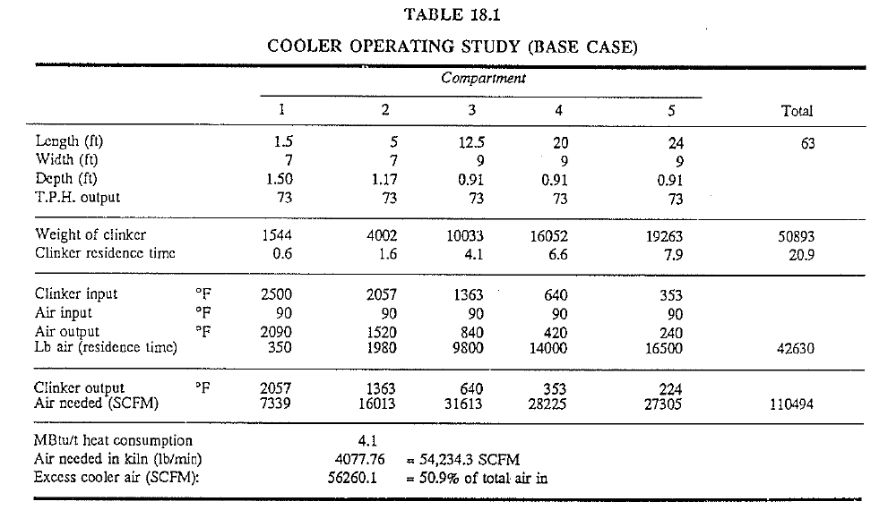
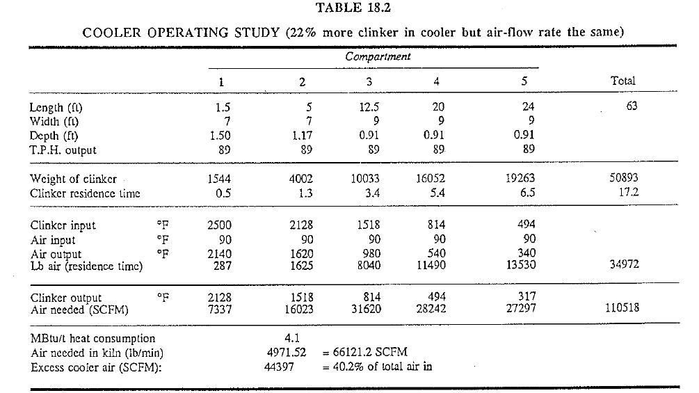
This approach in cooler control is usually satisfactory when the kiln operates in a stable fashion. However, during upset kiln conditions, or when the-clinker characteristics change, this approach leaves much to be desired. During such times, an operator can often experience difficulties in maintaining proper cooling of the clinker. For example, consider the base operating condition shown in Table 18.1 with a second compartment bed depth of 14 in. (36 em) at an hourly clinker throughput rate of 73 tons. In this base case, the clinker residence time in the cooler is 20.9 min and the clinker-discharge temperature 224 F. Now assume that the kiln suddenly starts to discharge clinker at a rate of 89 tons/h and that the grate speed is on automatic control, i.e., starts to increase the speed to maintain the same clinker-bed depth (see Table 18.2). Increasing this grate speed in an attempt to maintain a constant undergrate pressure, will then result in a reduction of the clinker residence time in the cooler, as shown in Table 18.2, to 17.2 min. This example shows that by pushing the hot clinker at a faster rate through the cooler and maintaining the same specific air-flow rate and undergrate pressure, the clinker-discharge temperature will increase to a theoretical 317 F. The lesson to be learned from these examples ; that whenever a significantly larger amount of clinker falls into the cooler and as a consequence the grate drive speed increases significantly, the operator must compensate for this with a corresponding increase in the specific, air-flow rate (SCFM).
other influencing factors that cause the undergrate pressure to change are the temperature of the clinker in the cooler and the amount of the introduced into the individual undergrate compartments. Assuming other factors to be constant a higher temperature of the clinker results in higher undergrate pressure and increased air-flow rates in the undergrat, compartments yield higher undergrate pressures.
Clinker residence time in the cooler can be determined on a theoretical basis when certain factors are known. For the purpose of illustration, three different cooler operating conditions will now be considered to determine the effects of changes of these critical variables.
Residence Time at Cosntant Output. Under these circumstances, the bed depth is directly proportional to the grate speed. Knowing the area of the cooler, the bed depth under normal operating conditions for a given kiln output rate, and the density of the clinker, the residence time can then be calculated by Eq. (18·1).
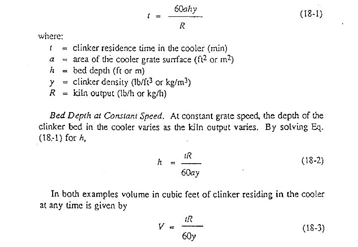
Residence Time ac Conscant Bed Depth. As mentioned previously, it is not desirable to maintain a constant undergrate pressure under all kiln out· put rates. This, of course, requires a constant bed depth, which means that the clinker residence time must be changed as the kiln output changes. Eq. (18·1) is used
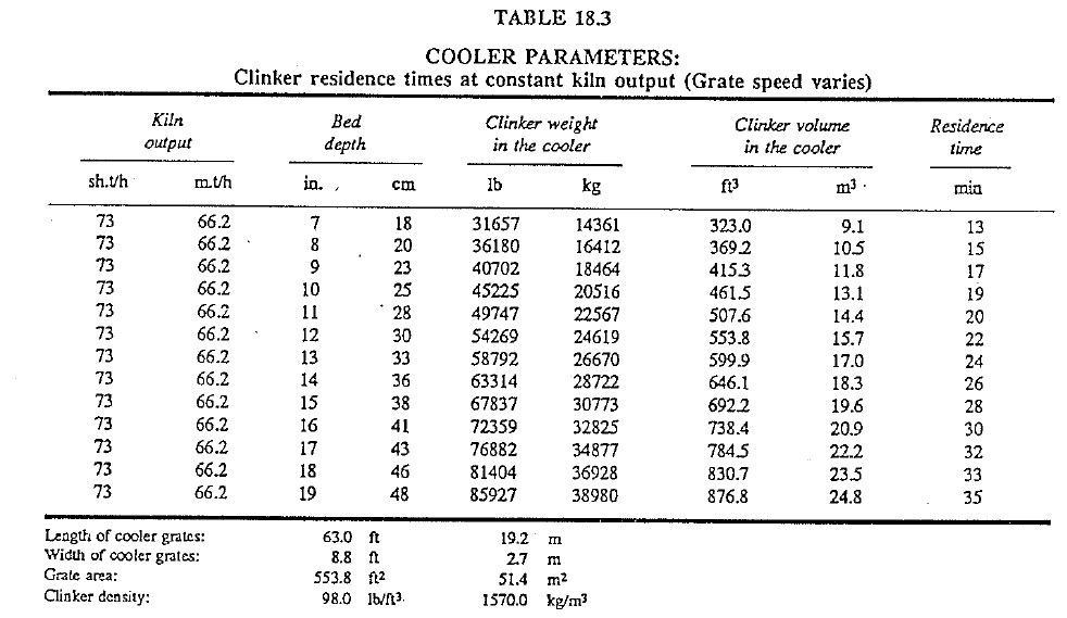
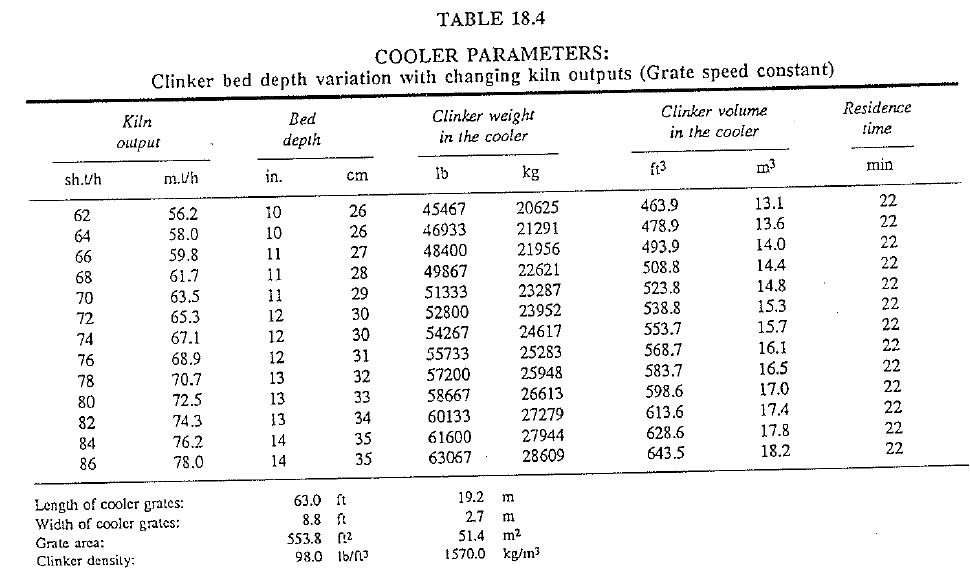
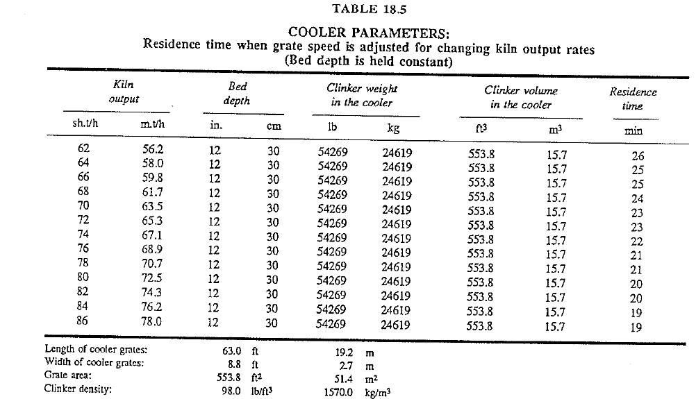
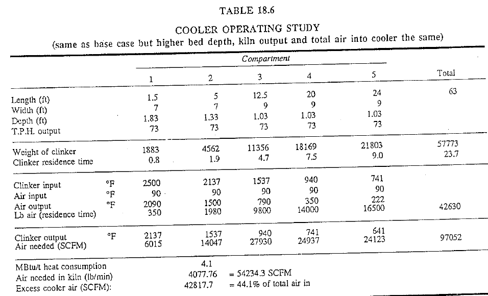
An operator should have no trouble in finding solutions for tl1e par ticular cooler he is operating, as the constants in the preceding equations can be substituted so that they apply to his cooler and kiln operation, and can be developed into tables similar to Tables 18.3, 18.4, 18.5, and 18.6.
the reader’s attention is especially directed to Table !8.5 which clearly shows the extremes that residence time can span at kiln output rates not uncommonly obtained during upset operating conditions. It also substantiates the statement that hot clinker-discharge temperatures can become a reality if insufficient time is allowed to cool the clinker properly.
It should now be clear that proper cooling is not obtained by operating with a constant undergrate pressure (bed depth) at all times, as it is definitely wrong to assume that undergrate pressure is a function of bed depth only. If this were so, cooler components would not burn up at such an alarming rate as now encountered on many rotary kilns.
PARTICLE SIZE OF CLINKER
A critical factor in undcrgrate pressure rcacticns is the average particle size of the clinker in the cooler. The reader may be familiar with the Blaine cement surface-testing procedure in which measurement is made of the time required to pass a specified amount of air through a standard sample of cement. It takes longer for the air to pass through a fine sample than a coarSe one because the finer material imposes greater resistance against the air. Exactly the same action takes place when the clinker in the cooler gets finer because of some upset kiln operating condition. A finer clinker bed imposes more resistance against air flow, undergrate pres· sure increases, and the fan has to use more force to push tl1e air through this kind of a bed than through a normal one. This however is not the only problem Individual clinker particles are lighter when the particle size distribution Such particles can easily be lifted into the air stream above the cooler grates because of their lighter weight.
From this it becomes clear that there are two changes in the cooler, one allowing the other. first the undergrate pressure increases when the clinker gets finer because the smaller particles impede air flow through the bed. Then, when the air flow rate is increased to restore the normal no\v of air through the bed, the clinker bed can become fluidized. As soon as this takes place, resistance of the bed to the now of air decreases and the undergrate pressure will suddenly drop. A fluidized clinker bed is a highly undesirable and dangerous condition because a bed in such a state usually does not move along properly in the cooler. On a horizontal grate cooler the clinker bed when fluidized tends to remain stationary with more and more clinker building up on it. Then when sufficient weight has been acquired by the bed and it starts to move again, there is so much clinker present in the cooler that it cannot be properly cooled, and it could again choke off air flow through the bed, starting the cycle over again.
It is a fundamental rule of traveling grate cooler operation never to permit raw feed or extremely fine clinker to enter the cooler. The most modem traveling grate cooler in use today is not designed to handle such fine materials and can become overheated and damaged if called upon to do so. The best procedure in such an instance is to lower the kiln speed in order that the load in the cooler is lessened, thus giving enough time for the fine clinker .to cool properly.
Another question which has to be addressed is: “How does the clinker discharge temperature react when the kiln output remains the same but the clinker bed depth in the cooler is increased?” Such an increase in bed depth is usually the result of:
- deliberate decrease in grate speed due to the selection of a higher undergrate-pressure setpoint or
- a design change where the effective grate area of the cooler is reduced.
Naturally, this increase in bed depth (undergrate pressure) immediately im poses a higher restriction on the cooler air fans and demands sufficient fan capacity to overcome this added restriction. Consider the base case (Table 18.1). Here, 42,630 lb of air are given to the cooler in 20.9 min to cool 50,893 lb of clinker. Assume that this cooler would be operated with a higher bed depth but with the same kiln output and 42,630 lb air input. This operating condition is shown in Table 18.6 and indicates that the clinker residence time has increased from 20.9 to 23.7 min. due to the increase in residence time, the 42,630 lb of air now represents a specific air flow rate of only 97,052 SCFM. The most important aspect of this change is that the resultant increase of the clinker-discharge temperature from 224 F to 641 F is completely unacceptable and dangerous. Here too, the solution is to increase the specific air-flow rate (SCFM) to compensate for the increase in bed depth.
OPERATION OF COOLER FANS
Now consider control of the rate of air flow in the cooler. The prime requirement in cooler control is to make sure that the air flow through the clinker bed is never restricted completely, because such a restriction leads directly to insufficient cooling of the clinker and possible damage to the cooler components. It has been pointed out that different clinker beds exert different resistances against the cooler fans.· To be able to understand this important fact more clearly, the operator must have some knowledge of how a fan works under actual operating conditions.
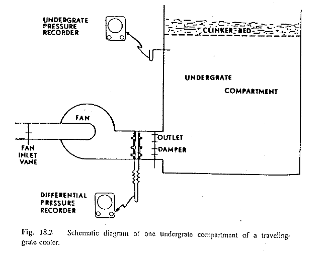
Fig. 18.2 is a simplified illustration of an undergrate compartment with its corresponding air fan. Air-volume control for cooler fans is most commonly carried out by means of either fan outlet dampers, fan inlet vanes, or sometimes both. The fan speed is constant for any one cooler fan so it is necessary for the operator to change the position of the damper or vane to reduce or increase the volume of air moved by the fan assuming no change in static pressure on the fan.
Fan manufacturers usually supply performance curves of individual fans for the customer. Fig. 18.3 is such a curve showing the volume of air plotted against horsepower and static pressure. In order that this discussion does not become too technical and enter fields over which an operator has no control, the horsepower curve will be disregarded and attention directed to the static pressure curve.
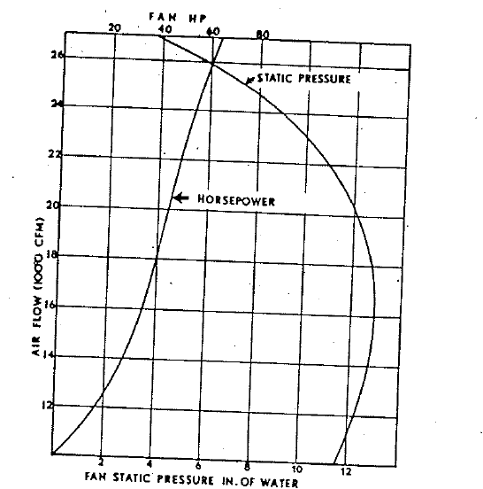
Fan static pressure is the total pressure developed by the fan, less the velocity pressure in the fan discharge duct For all practical purposes, fan static pressure in a cooler installation is equal to the undergrate pressure, within close tolerances. Air flow is a function of static pressure and power applied to the fan. To make this discussion more meaningful, substitute undergrate pressures for equal units of fan static pressures, and restrict the range of pressures to values as they are encountered normally on rotary. kiln coolers, thus obtaining new fan performance curves as shown in Fig. 18.4. The curve on the right represents the same curve as shown in Fig. 18.3, that is, the dampers of the fan are wide open, and the air flow is the maximum obtainable for this particular fan. This curve shows clearly how the air volume decreases as the undergrate pressure increases. For example, when the undergrate pressure is 9 in. of water with the damper wide open, 1e volume of air moved by the fan is 24,000 CFM: If the undergrate pressure increases, perhaps as a result of increased kiln output, the volume of air progressively decreases until at 12 in. undergrate pressure the volume is only 20,000 CFM. With the fan dampers wide open, an increase in undergrate pressure causes less air to pass through the clinker bed, creating the dangerous possibility of an overheated cooler and at the same time insufficient cooling of the clinker.
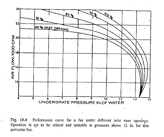
During normal and stable operating conditions, tl1e fan dampers or vanes are never fully open. In Fig. 18.4 additional curves have been plotted showing inlet vane openings of 90, 80, 70, and 60%. Usually, a cooler fan is operated at approximately 60% opening, thus giving the operator the necessary freedom to increase air flow if a kiln upset should make it necessary. For example, assume that the cooler is operating in a stable fashion with adequate cooling of the clinker at an undergrate pressure of 7 in., fan inlet vane at 60% opening, and air volume of 21,000 CFM. For some reason, t e undergrate pressure increases to 11 in. In order to obtain the same volume of air through the clinker bed,. the fan inlet vane opening must be increased from 60% to 90%. If the vane were not opened, the air volume would drop to 19,000 CFM.
These examples of fan performance under actual operating conditions point out two significant facts: First, as with any butterfly-type valve or damper, maximum flow is reached when the damper is about 88% open. Any enlargement in the opening thereafter gives only a very small increase in air flow. Second, air-volume output is directly related to undergrate pressure. Therefore, the fan must have sufficient capacity to provide the necessary amount of air at the maximum anticipated undergrate pressure.
A word of caution must be introduced here. Each fan installation will have its own characteristics. The fan curves discussed in this chapter apply to one certain installation and can be considered as typical, to show the reader the relationships between pressure, output, and power requirements. Reactions and capacities of any individual-installation must be computed for that particular combination of equipment. For this reason, it is advisable for an operator to examine the curves of the particular cooler fans that are under his control, and become familiar with their characteristics and capacities, so he will know the operating limits for undergrate pressure. Whenever the undergrate pressure exceeds these limits, the operator will know then that less efficient cooling is taking place and that an immediate change in kiln speed must be made to avoid damage to the cooler.
CLINKER AND AIR DISTRIBUTION THE COOLER
Finally, it is necessary to consider distribution of clinker and air in the cooler. For proper cooling of the clinker it is essential that the clinker is evenly spread over the width of the cooler so that the bed offers uniform resistance to the passage of air throughout its width. When the clinker passes to one side of the cooler, leaving a thinner bed on the opposite side, the air. will naturally seek a passage through the bed where it offers the least resistance. Consequently, the air passes through the bed where it is least needed and little air passes where it is needed most. Formation of stalagmites (commonly referred to as “snowmen” or “candles”) at the cooler inlet is the prime cause of this condition. Various devices are ·used to combat stalagmite formations. Some coolers have water cooled steel jackets, or water cooled clinker spreaders, and others have a special row of quench grates with their own air supply, to spread the clinker rapidly over the width of thee cooler at the inlet.
For proper distribution of air in the cooler no air should freely pass from one undergrate compartment to another through large leaks or other openings. If this is allowed to take place, the air introduced, for example into the first compartment, could pass over into the second compartment when the clinker bed is thicker at the cooler inlet.
Proper clinker distribution is an acute problem in tl1e upper region of many grate coolers. This problem can usually be overcome by:
- narrowing tl1e cooler width by means of installing refractory ledges and or “dead” grates along the cooler walls and
- concurrently increasing the static-pressure capability of the air fans in these narrowed
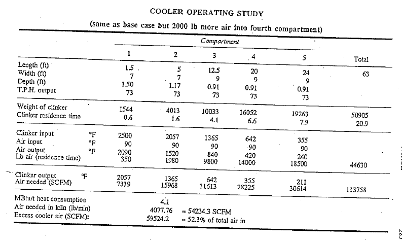
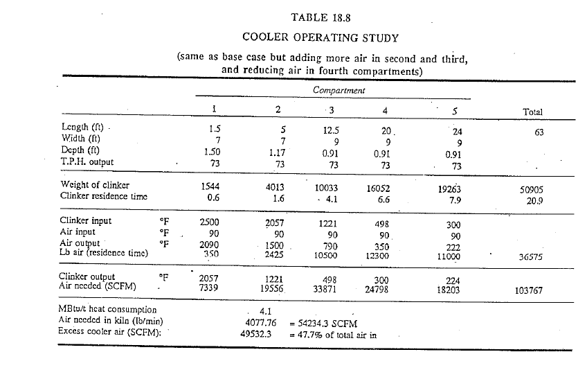
In Chapter 12 it was brieOy mentioned how important.it is to apply the maximum air in these compartments where it can do tl1e most thermal. work. This means, tl1e majority of the cooling work should be accom plished in the first and second compartments because it is here that the most efficient heat transfer will take place due to the large temperature difference between the air and the clinker. Once again, the base case in Table 18.1 is considered and it is assumed that 2000 lb more air is added into the fourth cooler compartment, i.e.; at the .place in the cooler where heat transfer is relatively ineflicient. Table 18.7 shows that this 4.7% increase in total air input results in a clinker-discharge-temperature drop of only 13 F (from 224 F to 211 F). It is assumed that all compartment air flows are readjusted to take advantage of the aforementioned thermo dynamic principle. In Table 18.8 air has been added to the second and third compartments while it has been reduced to the fourth and fifth compartments. The end result is that the total air input into the cooler has been reduced by 15% but the clinker-discharge temperature remains the same at 224 F. Once again, it is important for an operator to remember this principle of cooler-air application as this will lead to efficient cooler operation and possibly to less failures and damages to cooler components.
Undergrate pressures are usually set so that the highest pressure is found in the first compartment and the lowest in the last compartment. Clinker temperatures above the grates, as pointed out earlier, influence the under grate pressure. This step-by-step lowering of the undergrate pressures from one compartment to another is a natural result of the succeeding lower temperaures of the clinker as it travels down the cooler.
SECONDARY AIR-TEMPERATURE CONTROL
Secondary air temperature has a direct influence on the geometry of the flame and the point of ignition of the fuel, consequently irregular secondary air temperatures can cause irregular flame characteristics which in turn can cause a shifting of the burning zone. Stable kiln conditions are practically impossible as long as the secondary air temperature is not held constant, within a tolerance of± 100 F (40 C). The following discussion applies to controls to be exercised when the kiln is operating at normal speed and is producing well-burned clinker.
The kiln should be operated with the secondary air temperature as high as possible because the maximum amount of heat is then recovered from the clinker, thus improving fuel efficiency, as less fuel is required to raise the temperature of the air entering the kiln. This condition maximizes kiln capacity. A second advantage of high secondary air temperature is the favorable influence on the objective of burning the clinker close to the nose (front) of the kiln. However, there are practical limits for secondary air temperatures. A temperature that is too high can result in overheating in the kiln nose and the burner hood as well as in the cooler. It is advisable to operate the kiln with the secondary air temperature slightly below the maximum allowable in order to protect the bed grates and cooler refractory from damage.
The two factors having the greatest influence on secondary air temperature are speed of the bed grates in relation to the volume and temperature of air introduced into the cooler to cool the clinker, and temperature and size of clinker discharging from the kiln into the cooler. Under stable kiln conditions, the secondary air temperature is controlled by the speed of the cooler grates which merely means that the depth of the clinker bed in the cooler is the controling factor. Thus, an increase in grate speed (lessened bed depth), other conditions remaining unchanged, results in a lower secondary air temperature, and a slower grate speed (thicker bed depth) causes an increase in temperature. It is important to remember, however, that secondary air temperature control is not merely a matter of speeding up or slowing down movement of the bed grate. As mentioned earlier, there are several factors to be considered before deciding which adjustment will give the desired results.
Because the secondary air temperature is controlled mainly by the bed grate speed and the volume and temperature of the air in the cooler, as well as the temperature and size of the clinker, this control goes hand in hand with undergrate-pressure control, as any change in these two variables will also change the undergrate pressure. This then will considerably limit the extent to which secondary air temperature can be controlled.
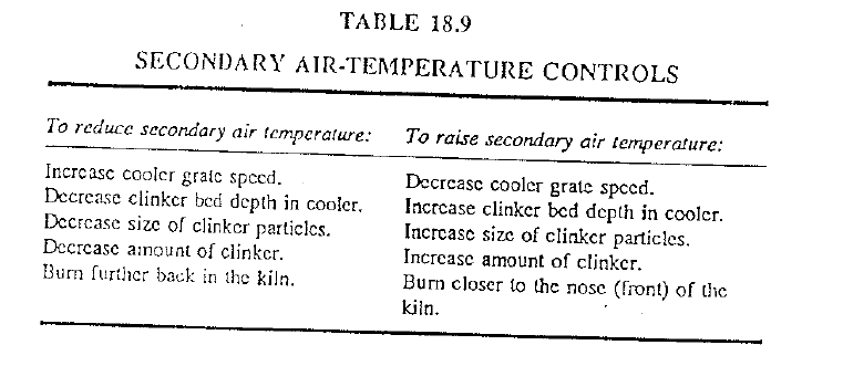
Now consider for example, an upset kiln condition in which the greatest part of the material in the cooler is in the form of very small-sized nodules, or even worse, in the form of dust. In a situation like this the operator will first reduce the kiln speed, which reduces the amount of clinker and consequently lowers the secondary air temperature (see Table 18.9). If an attempt is made to hold the secondary air temperature within a 100-degree tolerance, it would be necessary to slow down the bed-grate speed to such an extent that it would choke off the free passage of air through the bed. The clinker would thus not be properly cooled and would probably be red hot on leaving the cooler, causing considerable damage to the clinker transport equipment. The proper adjustment in this case would be to slow down the bed grates only to such an extent that the normal bed depth can be maintained. It is also extremely important that the air flow into the cooler be increased in order that the clinker can be properly cooled. The operator should never attempt to hold the secondary air temperature at its normal level when the kiln has been slowed down because of an upset.
The other factor to be considered in secondary air-temperature control is the temperature of the clinker as it discharges from the kiln. By changing the character of the name, the burning zone can be shifted closer to the kiln front thus raising the clinker-discharge temperature and consequently the secondary air temperature, or the burning zone can be shifted further back in the kiln, reducing the secondary air temperature. These actions are summarized in Table 18.9.
Earlier in this chapter it was pointed out that more air must always be given to tile cooler than what is needed for combustion in the kiln. Hence, a certain amount of excess air has to be vented to the atmosphere or used for the drying and grinding of raw materials and/or coal. On precalciner kilns, this excess air is diveided to the flash calciner by means of the tertiary air duct. By inference there must therefore be an imaginary dividing line in the cooler wherein the air in the hotter region goes to the kiln and the one in the colder part moves toward the cooler stack. Simple calculations on the operating conditions explained in Tables 18.1 and 18.8 would show that more efficient application of the air in the first two compartments would result in a shift of this imaginary line toward the upper end of the cooler, higher secondary air, and lower cooler-stack air temperatures.
Design limitations, either in cooler size or fan capacities, often lead to excessively high clinker-discharge temperatures regardless of how well the air distribution is controlled or the cooler mechanically maintained. Such kilns are usually capable of producing more clinker but the cooler acts as the bottleneck toward these higher output rates. Short of installing an after-cooler (such as the well-known G-cooler) or major modifications in cooler design, there is not much one can do to overcome these limitations. Some plants use water-spray cooling of the clinker within the last cooler compartment (usually leading to operating problems with the dust collector) or make use of reciprocating clinker “skips” combined with water sprays after the clinker discharges from the cooler. These solutions must be viewed as only temporary as most of these create additional operating problems.
HOOD-DRAFT (PRESSURE) CONTROL
A defmitive volume of air is drawn into the kiln by the !.D. fan and a given amount of air is forced into the cooler by the cooler fans. Years ago, on wet-process kilns with their high specific-heat consumption and relatively low kiln output, these two flows were nearly equal. Hence, only small amounts of excess air had to be vented to the atmosphere by means of the cooler stack. Some of these kilns were equipped with so-called closed-circuit cooler-air systems (recycling excess air to the upper cooler compartment fans) and successfully eliminated all excess air. However, as kilns became more efficient in heat consumption and clinker output rates, excess cooler-air volumes started to increase and in many cases this led to difficulties in hood-draft control. All too often the damper in the cooler stack which regulates the hood draft is found to be in the fully open position thus eliminating any effective control of the hood draft.
Hood-draft control is simply a regulation of the amount of excess air which escapes through the cooler chimney, so that when the hood pressure is too high, the damper must be opened, and when the hood pressure is too low, the damper must be closed. This does not mean that the damper has to be fully closed or fully opened, but instead small adjustments in the damper position can be made to give the desired results.
As mentioned, hood draft is governed mainly by:
- the D. fan speed and
- the volume of air given to the cooler
Assuming that other factors remain constant, then an increase in J.D. fan speed results in a lower hood pressure, and a reduction in I.D. fan speed results in a higher hood pressure. Similarly, increasing the amount of ak forced into the cooler results in higher hood pressure.
The hood pressure can be either negative or positive. A negative pressure indicates that the hood is under a vacuum, and a positive hood pressure means that the hood is pressurized. The basic rule in hood-pressure control is never to operate a kiln with positive hood pressure because this results in troublesome kiln operating conditions. Fine clinker particles are blown through the nose-ring seal thus causing the seal to wear out prematurely, and dust emission in the hood area can make viewing of the burning zone by the operator unpleasant and unsafe. On rotary kilns equipped with optical pyrometers and television cameras for burning-zone control, positive hood pressures could lead to damage to this equipment from the flying hot particles. Formation of rings and of stalagmites (“snowmen”) in the”cooler inlet can be attributed to positive hood pressures on some kilns. The importance of operating a kiln with negative hood pressure is obvious.
There is one situation in which the operator has to take exception to the above rule: Whenever prevailing high cooler temperatures could cause damage to the cooler components, it is necessary to introduce a sufficient amount of air into the cooler to lower the temperature and overcome the dangerous situation. The first corrective action in such an instance would be to slow down the kiln speed to lessen the load in the cooler. Then if dangerous overheated conditions still prevail and the damper at the chimney is already wide open, one has no other choice but to introduce an added volume of air into the cooler. However, the operator should return the !load pressure to negative again at the earliest possible time as soon as the situation has been brought under control.
The hood pressure is usually automatically controlled. The controller receives an input signal from the hood-pressure measuring instrument and sends an output signal to the damper at the cooler chimney. The operator adjusts the setpoint on the controller to the desired hood pressure (generally between –D.07 and –D.03 in. of water). Any time the hood pressure deviates from this setpoint, the chimney damper will then be automatically adjusted by the controller.
click here to Download the Most Important 13 Books in Cement Industry
click here to Download the Most Important 13 Books in Cement Industry
Good explanation