Contents
click here to Download the Most Important 13 Books in Cement Industry
click here to Download the Most Important 13 Books in Cement Industry
The Air Circuit in a Rotary Kiln
For a kiln operator, three variables that are related to air and gas flows anywhere within the kiln system are of special interest. These are:
- Volume and velocity
- Temperature
- Pressure
To determine the volume of a gas in a duct or flue, it is necessary to measure both the temperature and the velocity. Velocity is determined by means of a Pitot tube and differential pressure gauge. Other instruments used for this purpose are: anemometers (when the velocities are less than 3 m/s), orifice disk or Venturi meters (when gases move at high velocity or pressure through small pipes), or S-tubes that perform the same function as Pitot tubes except that they are used for measurements of dust-entrained gas streams. Strict rules apply and must be followed in order to obtain meaningful and accurate results when velocity measurements are made in a duct.
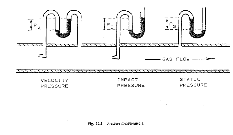
Pressure is measured and expressed by three different metl1ods: static pressure is measured at a right angle to the gas stream; impact pressure (often referred to as total pressure) is measured by pointing the tube directly into the center of the gas flow; and finally, the velocity pressure (often referred to as dynamic pressure) is measured by subtracting the static pressure from the impact pressure, as shown in Eq. (12-1).
![]()
![]()
Instruments used for measuring pressures are: dial gauges, U-tubes, and inclined draft gauges-the latter being the most sensitive and accurate of the three.
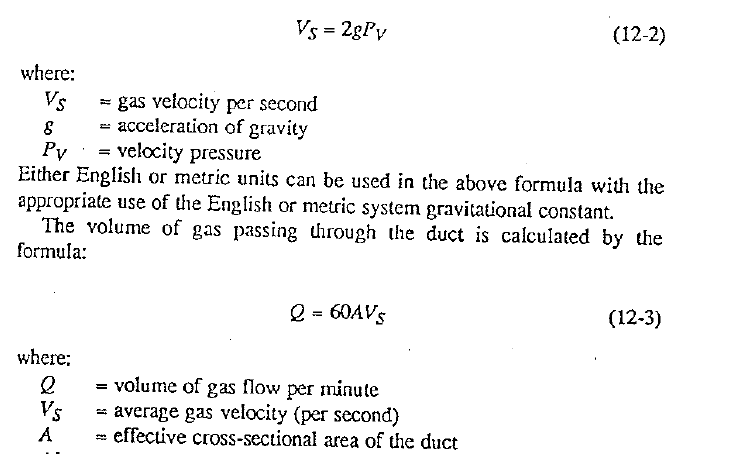
After accurate pressure and temperature measurements have been taken one can calculate thee air or gas velocity by the following formula:
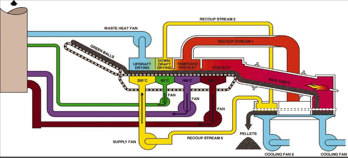
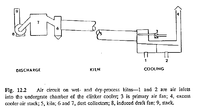
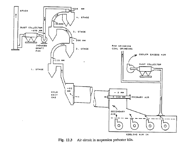
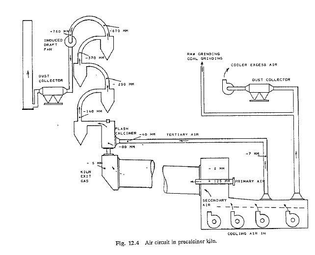
Air movement through the kiln can be considered, for all ·practical purposes, to take place uniformly from introduction of the air in the cooler to final discharge at the stack. In accordance with the gas laws, however, the physical state of the air undergoes changes in temperature, volume, and pressure while traversing the kiln. The reasons for these changes is that the chemical composition of the air itself changes in the process, and the spaces through which the air !ravels are not uniform throughout the system. Figs. 12.2-12.4 show schematic diagrams of complete air circuits of the various kiln systems in use in the cement industry.
For convenience, it is customary to divide this air flow into three successive circuits in the following order:
A)the circuit for cooling of the clinker and introduction of combustion air into the kiln. this is the cooler circuit
B) The circuit in which combustion, calcination, and drying takes place. This is the kiln circuit
C) The circuit in which the air and gases are released from the kiln and pass through the heat recovery and dust-collecting This is the discharge circuit.
In considering the air circuit in the kiln, it is necessary to look at all three divisions as a whole because one leads naturally to the next. The whole concept of air flow is one of a complete unit, as any adjustment or change in one circuit will effect a change in the entire air circuit. Another important factor is that it is almost impossible to avoid the entrance of so called cold parasite air into the kiln system. This air enters through badly closed openings around the kiln hood and around the back-end ducts. Not only does this cut down the efficiency of the induced draft fan, but the cold air entering through the hood and nose area reduces the fuel efficiency. Drastic changes in the air flow take place when doors anywhere in the system are left open for a prolonged length of time. Because this could lead to upset kiln conditions, it is important to advise the operator in advance when such an action is to be undertaken.
THE COOLER AIR CIRCUIT
The clinker cooler performs two functions: it must cool the hot clinker discharged from the kiln and supply the kiln with the necessary air for combustion. In doing so, valuable heat from the clinker is recuperated and enters the kiln as hot secondary air. The most common clinker coolers in use are:
- inclined reciprocating grate coolers
- planetary coolers
- continuous traveling grate coolers
- rotary coolers
On kilns with large clinker outputs or special cooling problems, additional cooling of the clinker is often required after it discharges from these coolers. This is being done by adding a so-called after-cooler to the above units, the best known type of this kind being the G-cooler manufactured by Claudius-Peters. Such after-coolers are also viable alternatives (instead of installing completely new coolers) in cases when a kiln is being converted from wet to dry, dry to preheater, or from preheater to precalciner status, all of which produce a need for increased cooler capacity due to anticipated higher clinker output rates. Unlike conventional coolers, there is no direct contact between the clinker and the air in a G-cooler, hence, this type of equipment is almost free of dust emissions. G-coolers provide the final clinker cooling, receiving clinker at a temperature of around 350 C (660 F) and discharging clinker at a temperature of approximately 100 C (212 F).
The inclined reciprocating grate cooler is the most widely used type of
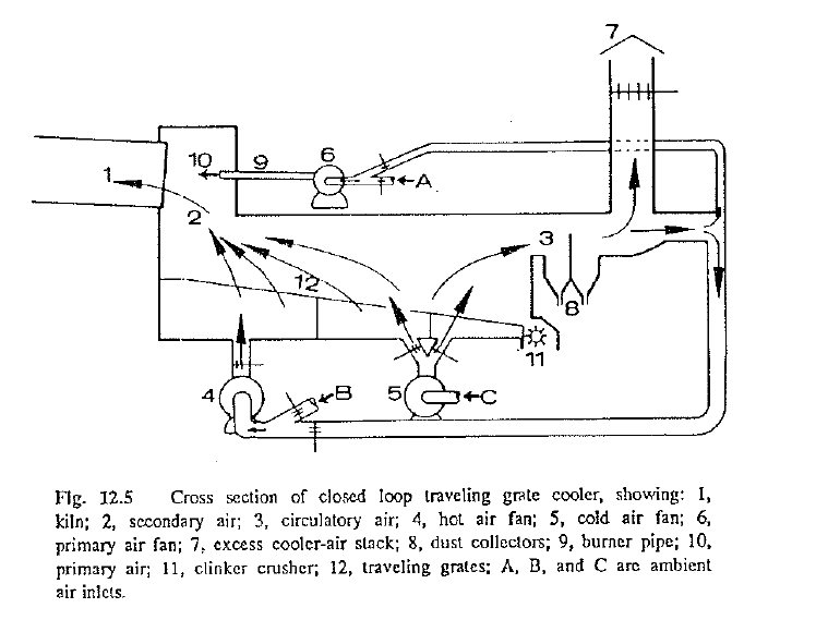
cooler today. This type of cooler derives its name from the reciprocating (back-and-fortll) movement of the rows of cooler grates that push the clin ker toward the discharge end. As many operators can attest to, this type of cooler can not properly and efficiently perform its function when the clinker is very fine as in the case where the kiln is in an upset condition. Fig. 12.5 shows a schematic cross section of a closed-loop traveling grate cooler. This type of reciprocating grate cooler has found some ap plications in wet-process kilns where combustion air requirements in the kiln are usually very high. Circulating warm air from the lower section of the cooler and using it for cooling air in lhe upper compartment lowers the total excess air that has to be vented to the atmosphere and is thus bene ficial toward controlling the emissions from the cooler. However, this system has its application limitations and is usually not suitable for large dry and preheater kilns that are energy efficient and produce a large amount of clinker per hour. Nevertheless, it is known that there is at least one precalciner kiln that uses tl1is kind of a system successfully in the United States. There is a limit to which air can be recycled within the cooler compartments in order to maintain rapid quenching in the first cooler compartment. Coolers equipped with such a system often experience rapid cooler fan blade wear when the recycled air contains a large amount of dust.
Cooler operating problems have become more pronounced as kilns started to get larger and their output rates increased. Most grate coolers require the use of a much larger amount of air for cooling the clinker than what is needed for combustion in the kiln. Hence, modem coolers operate with lager cooler excess-air volumes that are not usable for combustion in the kiln. To prevent these heat losses, this excess air is usually used for drying ti1e kiln feed and/or coal and, in precalciner kilns, is transferred to the flash furnace to be used as combustion air in ti1e auxiliary firing unit.
Planetary coolers are cooling cylinders that are attached to the circumference of the rotary kiln. There are no moving parts on these types of coolers, no fans to control, and all the air that passes through these tubes enters the kiln and is used for combustion. It’s the simplest system for cooling clinker and there are no control functions except the rotational speed of the kiln itself. Planetary coolers are equipped with lifters, agitators, and blades to promote the heat exchange between the hot clinker and the cold air. With all the air entering the kiln, there are no dust emission problems from these types of coolers. On larger units, noise pollution can, however, become a problem from the clinker rattling in the tubes. Planetary coolers require a larger l.D. fan than kilns of equal size equipped with grate coolers but the total power requirements are much lower when one considers all the air fans usually found on grate coolers. The disadvantage of planetary coolers is that most will discharge the clidcer at a higher temperature than compatible grate coolers.
The continuous traveling grate coolers are similar to the reciprocating grate coolers except that they use a continuous moving grate belt Advantages of this type of cooler are that individual worn or damaged plates can be quickly replaced without needing to stop the kiln. Also, since the belt travels from the hot to the colder part of the cooler and returns underneath where it is being cooled by the cold air, overheating is less likely to occur here than in reciprocating grates.
Rotary coolers were first used over 80 years ago, however, in order to be efficient in today’s modem kilns they would have to be of such size as to make them financially unjustifiable. There is some doubt that this type of a cooler would ever make a comeback in the cement industry despite its simplicity of operation.
Every cooling system must have an air balance to ensure proper cooling of the clinker as well as proper combustion in the kiln. Any excess air from the cooler not needed for combustion has to be vented to the atmos phere or must be used for other thermal work.
Efficient operation of a cooler requires that the minimum amount of air with the lowest possible temperature be vented to the atmosphere while at the same time the clinker is cooled to the temperature that ensures trouble free transport of the clinker to the storage area after it leaves the cooler. Dampers ar.d regulators must be so adjusted that no overheating of the cooler equipment can take place, and the primary air and secondary air are blended in the proper proportions when they enter the kiln. Temperature of the secondary air entering the kiln should be as high as possible in order to recoup a maximum amount of heat from the clinker, provided the cooler and kiln nose are not permitted to become overheated.
On grate coolers, cooling is accomplished by forcing ambient air up ward through the grates and the bed of material. To obtain optimum cooling it is important that the proper bed resistance is maintained. This insures proper retention time for the clinker and efficient heat transfer. As the cooling air passes through the clinker bed and acquires a higher temperature, its volume is expanded. As the air expands, more force is required to push this air through the bed. Since the material is hottest at the inlet to the cooler, it follows that the cooling air expands the most here and requires the highest pressure at this inlet side. Further down, the heat transfer rate becomes less, causing less expansion of the air and thus requiring less pressure to get through the bed. This is the reason for installing several compartments in these coolers and equipping each with a fan of diminishing static-pressure rating. When this important factor is overlooked in the initial design phase, or when the cooler is not properly and efficiently compartmentalized, cooling efficiency of the unit as a whole is sacrificed.
After the cooling air passes through the bed of clinker, the air needed for combustion is drawn· into the kiln as the so-called secondary air by the !.D. fan or forced into the kiln as primary air by the primary air fan. The remaining air is either vented to the atmosphere or used for drying coal or raw feed. In the precalciner kiln, this excess air is transferred to the flash furnace by means of the tertiary air duct .
It is a fundamental requirement that the air forced into the cooler is applied to these areas where it can do the most useful thermal work. In thermodynamics, the best heat-transfer potentials take place where the temperature differential is the greatest. It follows that it is necessary to apply the maximum amount of air in the upper (hot) compartments and a minimum amount in the lower (cold) compartments. This can be clearly demonstrated by using the common heat-transfer Eq. (12-4):
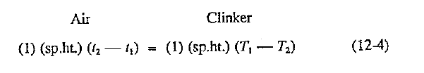
Inserting the appropriate values for the variables, this demonstrates that one pound of ambient air has the capacity to lower the clinker temperature in the first compartment from 1260 C (2300 F) down to 748 C (1378 F), i.e., producing a temperature drop of 512 C (922 F) in the clinker. However, the same pound of ambient air, applied to the last cooler compartment will be able to drop the temperature of a “colder” clinker of, e.g., 300 C (572 F) by only 13 C (23 F). In other words, the heat transfer in the first comparunent is 30 to 40 times more efficient than the heat transfer in the lower compartment. This serves as a clear reminder to operators that they should always first make sure that the air is properly applied in that part of the cooler where it can do the most thermal work. This becomes especially important in situations where a cooler exhibits very high excess ak volumes that must be vented to the atmosphere. The same reasoning must be applied when the clinker cooler consistently discharges insufficiently cooled clinker that produces high finish-grinding temperatures and could lead to quality-control problems in the cement Many cooler-operating problems have been, and can continue to be, solved by applying this important rule of cooler operation. Damage to cooler components often occurs when an operator neglects to recognize when the air flow to individual cooler compartments is not properly adjusted to prevailing operating conditions.
It is a recommended procedure that the plant engineering staff checks the cooler air flows and establishes a cooler air balance at least once per year to keep up-to-date information regarding the cooler’s efficiency.
THE ROTARY-KILN AIR CIRCUIT
The amount of air drawn through the rotary kiln is governed and controlled solely by the induced draft fan (l.D. fan) located at .the feed end of the kiln. The origin of the air going to the kiln is:
- I) the hot secondary air emanating directly from the cooler,
- the moderately heated primary air entering through the burner pipe, and
- the parasite air that enters through leaks and openings in the kiln hood area
The ultimate objectives are: a) to induce a maximum amount of hot secondary air, b) to use only the minimum, safe amount of primary air that is needed for fuel conveyance and flame control, and finally c) to remove or reduce the presence of parasite air. For every pound of cold air (e.g., 30 C) drawn through these unnecessary in-leakage points in the hood, there is a corresponding pound of valuable hot secondary air of around 800 C that will not be put to useful work in the kiln. The end-result is that a higher volume of excess cooler air has to be vented into the atmosphere. The temperature of this air is also being increased resulting in the waste of more valuable heat The kiln operator must always try to stabilize the air flow through the kiln. Unless the kiln draft is controlled within reasonable limits, a uniform firing rate and stable burning conditions can never be obtained.
A certain definite amount of air is required for complete combustion in the kiln, which means close control over the fuel-to-air ratio has to be exercised. Incomplete combustion, caused by the admission of too little air, results in the loss of some unburned carbon because a portion of the carbon in the fuel is burned to carbon monoxide (CO) instead of carbon dioxide (C02). To make sure that this does not take place a small amount of excess air (approximately 5%) is introduced into the kiln. On the other hand, too large an amount of excess air could lead to serious heat losses because this air, not needed for combustion, raises the temperature of the gases leaving the kiln at the rear. This rise in temperature in tum affects cl1e heat profile in the kiln, because of the change it causes in the drying, calcination, and burning-zone conditions. Once a kiln operation is stabilized, the following three basic rules must be observed in order to maintain the kiln in such a condition:
- Complete combustion conditions must prevail at all times while a kiln is in operation, thus fuel and air rate changes can be undertaken only to the extent that no formation of carbon monoxide will result after the rates have been changed.
- The maximum amount of excess air present in the kiln should not exceed the amount that will cause heat losses to the rear to surpass the predetermined limit
- Temperatures of the air entering the kiln and leaving the kiln should be held as nearly constant as possible in order not to upset the heat profile in the kiln.
By weigh each unit of fuel burned (lb or kg) requires approximately units (lb or kg) of combustion Air, at standard conditions, has a specific volume of approximately 0.7735 m3fkg (12.39 ft3/Jb). Hence, to bum 1 kg of fuel requires approximately 8.12 m3 of air for combustion in the kiln. Likewise, burning l lb of fuel requires approximately 130 ft3 of air at standard conditions. The gases produced during the combustion process travel toward the rear of the kiln and are enriched with:
A) carbon dioxide evolved from the feed during calcination,
B) water from the evaporation of the moisture in the feed,
C) volatile constituents that have evolved (e.g., sulfur and alkalies),
D) dust evolved within the system
Clearly it stands to reason that a wet-process kiln, where all the calcination (C02) and aH the evaporation of the moisture in the fed takes place within the rotary kiln proper, has the highest gas volumes per unit weight of clinker produced. Conversely, the precalciner kiln, where most of the calcination is done in the preheater tower and no moisture is present in the feed, has the lowest volume of kiln gases leaving the rotating kiln.
Gas-flow rates can be either calculated based on theoretical parameters or actually measured by the aforementioned measuring methods. However, actual measurements, particularly kiln exit-gas flows, will always be suspect for accuracy unless strict adherence to established measuring rules is practiced. It is also very difficult to establish the actual cross-sectional area of the duct, at the point of measurement, because there usually are no accurate means to determine the size of the coating buildup in the duct. It is therefore good practice for an engineer to calculate the theoretical flow rates as well as to ascertain that the actual measured values correspond closely to the theoretical results.
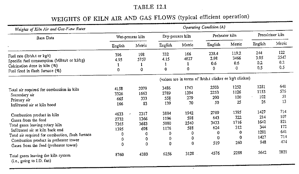
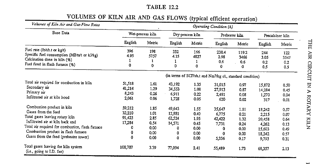
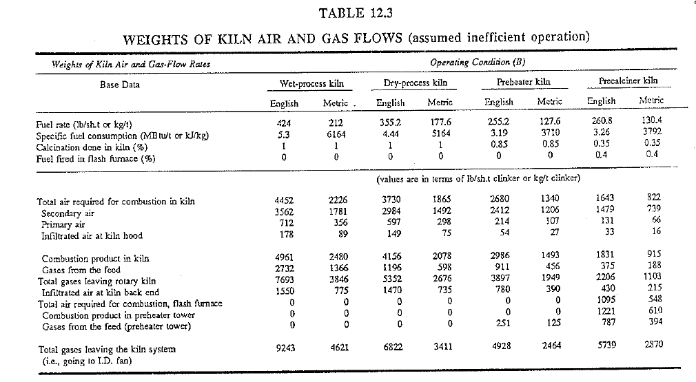
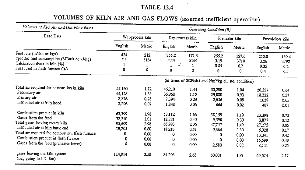
In the following tables (fables 12.1-12.4), kiln-air and gas-flow rates of the four main kiln systems discussed in this book are shown. Operating condition (A) in Tables 12.1 and 12.2 refers to what is considered efficient operations. Operating condition (B) in Tables 12.3 and 12.4 has base data altered to show how the gas weights and volumes can change on the same kilns as a result of less efficient operating These tables have been developed on theoretical considerations only for the purpose of demonstrating how changes in fuel and calcining rates can change the gas-flow rates in the kiln.
Each individual type of kiln design has an established, by design, pressure drop across the system. Fans are thus designed to overcome this pressure drop or resistance under normal operating conditons. Unfortunately, these pressure drops do not remain constant since added restrictions in the form of buildups and rings can significantly increase this pressure drop. Pressure-sensing devices that monitor pressure changes within the system are a useful tool for operators to detect formation of such restrictions. This is discussed in detail in the chapter on kiln control.
THE DISCHARGE AIR CIRCUIT
Once the gases leave the kiln system (preheater tower), there remains the task of removing the dust in tl1ese gases before they can be vented to the atmosphere. Multiclones, cyclones, electrostatic precipitators, andlor dust-bag houses are installed for this purpose. Without entering into a detailed description of various dust·coilecting systems, it can generally be said that all these units cause an appreciable loss of pressure in the gas stream, which makes a large capacity of the induced draft fan a necessity. The more dust-collecting units and the shorter the chimney or stack, the more energy and fan capacity required to pull the gases through the kiln system.
The operator should keep in mind that the I.D. fan is designed to handle the hot kiln gases given off during normal operating conditions. If the fan is called upon to move an equal volume of relatively cold gas, it could be overloaded because the cold gas has a higher density (is heavier) than the hot gas. For this reason, tables for maximum fan speeds at various exit· gas temperatures must be furnished to operating personnel.
Although the discharge air cirucit is not directly related to the actual
production of cement, it nevertheless requires close attention from the operator. An operator must focus his attention upon the temperature of the gases at this location of the air circuit because either too high or low a temperature can be harmful to the dust-collecting equipment. The mois ture and tl1e sulfur content of the gases require that this temperature be controlled within a predetermined range. If tl1e temperature falls below the dewpoint of the gases, the moisture can precipitate out in the baghouse or electrostatic precipitator, causing plug-up problems and chemical attack due to corrosion. Filter bags also have a given maximum-service tem perature above which these bags can be damaged. Most baghouses require that tl1e gases passing tl1rough do not exceed 285 C (545 F). The dew point of the gases varies depending on local prevailing conditions. Experience has shown that when the dust-collector inlet temperature is held above 160 C (320 F) there exists little danger of moisture precipitating out in the collector. In summary, it can be stated that most kiln systems have to operate the dust-collector inlet temperature within the range of 160…285 C (32()…545 F) to prevent operating problems in the dust collector. It is important to remember that these temperatures apply to the dust-collector inlet and not to the.kiln exit or preheater-tower exit-gas temperature.
The reader might question the aforementioned dewpoint temperature for it is true that the dewpoint for k!ln gases is normally between 50-90 C (120-195 F). Why then the adherence to the higher temperature given above? The answer is infiltration in the dust collector itself. Kiln gases are being further cooled inside these units by as much as 60 C (140 F) which can bring these gases close to the dewpoint even when they enter at a much higher temperature.
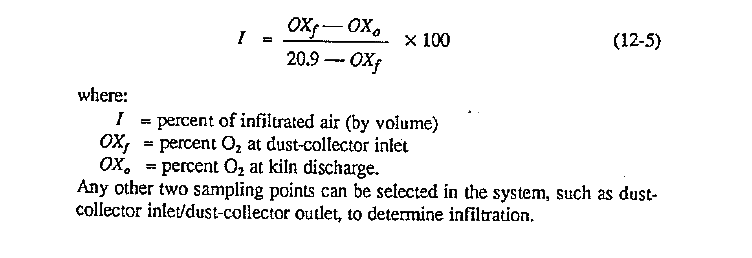
Another factor that has to be considered in respect to the discharge air circuit is the air inleakage between the kiln exit and the dust collector. This in leakage should be held to a minimum by effective sealing of all unnecessary openings. These openings diminish the induced draft fan (J.D. fan) capacity, require extra power to drive this fan, and could drop the gas temperature below the previously discussed, harmful dewpoint It can be calculated that 25% infiltrated air at the discharge circuit can increase the horsepower requirements of the I.D. fan by an approximately equal amount of 25% which is a significant inefficiency in the system. Sealing doors and openings within the gas ducts is normally not difficult but, obtaining an effective kiln back-end seal is usually associated with high installation and maintenance costs. Nevertheless, these expenditures for effective seals can be financially justified by the resulting reduced horsepower requirements of the fan.
The amount of air infiltration at the discharge circuit can be measured by extracting and analyzing simultaneously the gases at the kiln exit and the dust-collector inlet The percent infiltrated air is then calculated by Eq. (12-5):
click here to Download the Most Important 13 Books in Cement Industry
click here to Download the Most Important 13 Books in Cement Industry