Contents
To download the below and all other Useful Books and calculations Excel sheets please click here
To download the below and all other Useful Books and calculations Excel sheets please click here
Advanced techniques to Prevent Kiln Lining Failure
The productivity in a cement plant mainly depends upon the availability of the kiln. The present day rotary kilns are having large diameter and it is most essential to maintain their mechanical stability. The kiln alignment, deformation of shell, ovality, etc. are some of the factors which play an important role in maintaining the good refractory life.
In this paper, an attempt has been made to analyse the causes of refractory lining failure, specially with reference to mechanical stresses on bricklining.
INTRODUCTION
The cement production all over the world including India is growing very fast to match the demand & supply pressure in the market. The market of cement sales is very competitive that is why the profit margin has very narrow band between production and sales. Any type of interruption in production of cement can affect the profitability. Kiln is the most crucial equipment of cement manufacturing process and the productivity largely depends on the kiln operation and its availability. In the past experience, it is observed that the main interruption in cement production is due to the failure of refractory. The statistical data show that the refractory failure has around 80% contribution in total kiln down time.
The investigations show that the causes of refractory failure and poor durability of refractory in large diameter kilns are due to the following factors.
- Grade & lining methods of refractory
- Operational influence
- Mechanical stresses on the refractory
The grade and lining methods of refractory and kiln operation in rotary kiln have undergone considerable changes in recent past. With the development of various new generation refractory bricks and technological upgradations, significant improvement in the service life of kiln refractory is being experienced. The paper discusses the causes of refractory lining failure with reference to mechanical stresses which are due to the following factors:
- Kiln shell ovality
- Kiln shell warping
- Kiln alignment
- Mechanical condition of kiln
KILN SHELL OVALITY
Terminologies
The refractory life in the area of kiln tyre is significantly influenced by kiln deformation i.e, the shell ovality. As a result of changes in the kiln shell radius, there is a movement between the bricks which results in local surface pressure which leads to rapid wear or the collapse of the lining. For proper understanding of subject the terminologies such as creep, tyre clearance and ovality are explained below:
Creep
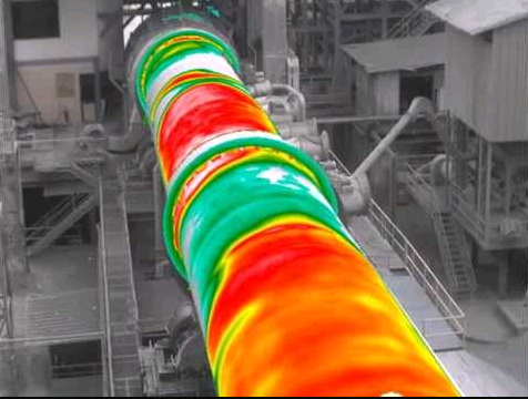
cylindrical, undeformed tyre having inside diameter as “Do” and undeformed outside diameter of kiln shell, above chairs, as “do”.The theoretical clearance between the two perfect cylinders is “C”.
During each revolution there is a relative movement “U” between the tyre and the shell which is equal to the difference of the circumference which is called as creep and is defined below.
Tyre Clearance
During operation, the tyre is deformed due to the station load and becomes elliptical as shown, in exaggerated manner, in figure 3. The horizontal inside diameter of tyre is “Dh” and vertical inside diameter as “Dv”. The shell inside the tyre has an outside horizontal diameter of “Dh” (equal to inside diameter of tyre) but the vertical diameter is smaller than “Dv” by a gap “S”, called tyre clearance.
Ovality
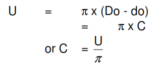
Ovality is the cross sectional deformation of the kiln shell during each revolution in the region “X” to “Y” and can be measured by “Holderbank’s Shell Test Apparatus”. It produces a polar diagram which represents the cross section of the kiln during operation.With the help of a polar diagram, absolute and relative ovalities are calculated by the following formula.
To prevent rapid wear of brick lining, the relative ovality should be kept within the reasonable limits. Figure 5 indicates relative ovality limits as a function of kiln diameter. It is observed that for a kiln of 3 m diameter the relative ovality should be around 0.3% whereas for a kiln of 6 m diameter, it should be around 0.5%
Measurement of Creep and Tyre Clearance
With loose tyres the monitoring of creep and tyre clearance is important, which can simultaneously be measured with a simple device shown in figure 6. It consists of a pointer and a recording plate. The pointer is attached to the kiln shell by a magnet and pressed in contact with the recording plate which is secured with help of a magnet on to the tyre. The creep “U” and the tyre clearance “S” can be read directly from the plotted profile. If above instrument is not available the creep can be determined by suitably marking tyre and the shell and then by measuring displacement between tyre and shell.
Theoretically U = p x S but practically U = 2 x S only. It is recommended that a tyre clearance of 3 to 4 mm (creep of 6-8 mm) should always be maintained for proper floating of tyre.
Effect of temperature on Tyre Clearance
In case the shell under tyre is overheated, or heated rapidly during startup, clearance “S” starts reducing and in case the shell is heated further, it becomes zero. If the shell is further heated, it results in the constriction of shell i.e seizing of shell with the tyre as also the shell can be pinched inside, damaging the kiln shell permanently. Typically the difference in temperature between shell and tyre must not increase 150oC. In case this temperature difference increases more than 150oC, shell should be cooled down by the cooling fan as shown in figure 7. The fan has to be so arranged that the cooling air passes through the gap between two consecutive chairs.
To avoid undesirable eventualities of shell seizure, a system for monitoring the creep of the floating tyre continuously, with an alarm and cooling system can be installed. When the creep goes down the recommended limit, the alarm blows and the cooling automatically starts. In case installation has only alarm, the heat input to the kiln must be quickly reduced and the shell temperature brought down.
Correcting Tyre Clearance
In case life of lining near the tyre is unsatisfactory and the tyre clearance is too large, the only option is to correct the excessive tyre clearance. This can be done by inserting shims or by changing the old chairs by new chairs of suitable thickness.
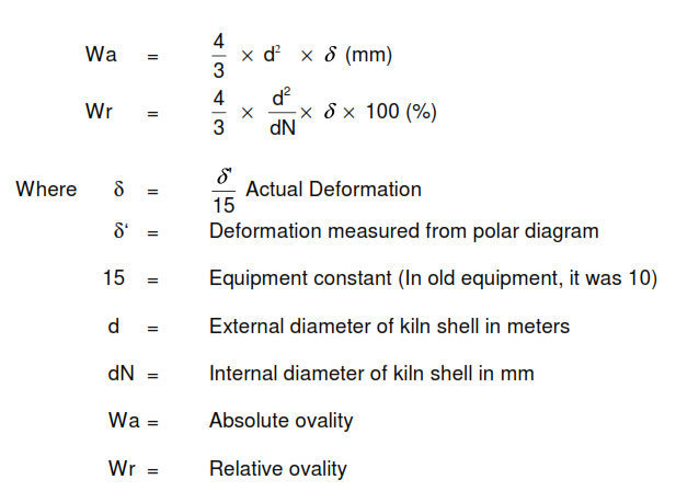
To evaluate the shim thickness, the clearance should be recorded and plotted for a week . Based on lowest recorded clearance, the shim thickness is calculated as below:
In case of bolted chairs, the shims can be inserted by loosening the bolts and inserting shims between shell and chairs. In case of welded chairs, the shims can be tack welded over the chair as a short term measure and during long shutdown of kiln the old chairs can be replaced by new chairs of correct thickness.
KILN SHELL WARP
Bricklining life is adversely affected if the kiln shell is warped. Under heavy rain if kiln suddenly stops and there is no means to rotate the kiln slowly, the temperature difference between the upper and lower portions of the shell may be
as high as 200 – 250oC. Under these circumstances, the upper part of shell tends
to contract whereas the lower part tends to expand and the kiln shell bends from its rotational axis. This type of deformation would form a banana shape of the kiln and is called warping of kiln. It can be seen that because of shell warp all the tyres are not in contact with the support rollers, and thus, the loading of the support rollers shall not be uniform. The excessive loading of support rollers is more acute in case of short dry process kilns as these are more rigid in comparison to wet process kilns
Consequences of Shell Warp
A warped rotary kiln will have following consequences:
- Variable bearing reactions during one rotation of kiln
- Drive motor draws high current and large variation in current drawn
- Change in contact pattern of girth gear and pinion
- Disturbed kiln alignment
- Excessive false air entry because of misalignment of inlet and outlet seals
- Frequent failure of bricklining
- Lifting of tyre on one or more support rollers
Measurement of Kiln Warp
Kiln warp can be assessed/measured by following methods:
- Laser Beam Method
On kiln shell, in both planes, measurements are taken at an interval of 1 metre. The analysis of shell axis reveals the quantum and the plane of warp.
- Polar diagram method
Polar diagram of the shell can be drawn at every 1 metre. The analysis of the polar diagram reveals the quantum and plane of warp.
Kiln Warp Correction
Kiln warp is difficult to correct fully. However the operation of kiln can be improved by correcting the radial and facial runout of girth gear and simultaneously adjusting the pinion for required contact pattern. The replacement of worst affected shell shall considerably improve the warp.
KILN ALIGNMENT
Definition
A kiln is supposed to be aligned if its rotating axis is rectilinear. In other words, if the rotating centres of shells at centre of tyres are joined together, these should form a straight line, in horizontal as well as vertical plane
Accuracy Requirements
Based on operational experience, the accuracy requirements for kiln alignment, for its proper operation, in horizontal as well as vertical plane are + 1.5 mm and + 2.5 mm respectively
Cold Kiln Alignment
This can be carried out by taking the measurements while the kiln is stopped. The cold alignment has many limitations, however, a few are listed below:
- measurements are not very accurate
- wear of tyres, rollers and chairs is not considered
- effect of temperature is not considered
Despite above limitations, this method of alignment is in use in many cement plants, since its cost is quite low as compared to the hot kiln alignment.
Hot Kiln Alignment
In this method, the readings are taken while the kiln is operating at full production. The readings obtained are fairly accurate. However, this method of alignment is costly.
Alignment requirement
For improving the refractory life the kiln should be aligned every 2 years preferably by hot alignment method.
MECHANICAL CONDITION OF KILN
Kiln Shell Runout
The shell runout should be maintained between ± 6 mm. In case the shell runout crosses this limit, it will have a detrimental effect on the bricklining life. In such an event the specific shell which is causing runout, should be replaced.
Radial and facial runout of girth gear
Girth gear should be checked for axial and radial runout at regular interval to suit the plant shutdown schedule and when there is a possibility that the alignment might have been affected by shell deformation or other reasons. Following are the acceptable limits for axial and radial runouts for new installations as well as used/old installations for different gear pitch circle diameters.
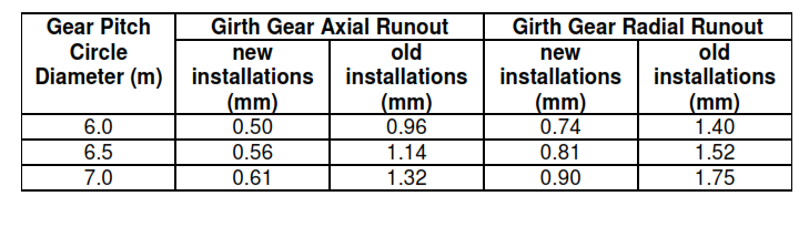
To obtain extended life of girth gear and pinion the runouts should not exceed the acceptable limits. When the readings show excessive runouts the girth gear should be re-aligned.
Pinion-Girth Gear mesh
Backlash, pitchline separation and root clearance should be periodically inspected and corrected whenever required. The contact area of girth gear and pinion teeth should be maintained between 70-80%.
Skew of rollers
Excessive skewing and wrong skewing of rollers may create heavy thrust reaction on the bearings and at times vibrations which are detrimental to the lining life.
For proper skewing, each roller should be brought to the neutral position and then skewed in the right direction by 0.13 to 0.26 mm at a time, followed by a waiting time of around 4 hours. All the thrust rollers should be skewed to take the thrust equally.
The modern trend is to keep the rollers parallel to the kiln axis and provide a hydraulically operated thrust roller for floating the kiln. But, careful and controlled skewing of rollers is preferred to avoid full time loading of the thrust roller assembly.
Lubrication of tyre
When the shell is heated rapidly to the extent that zero clearance is reached the chances of seizing of tyre with shell can be reduced by lubricating the tyre. This lubrication will also reduce wear of chairs. It is recommended to lubricate the bottom of tyre by injecting graphite/copper based lubricant into the space between tyre and the chairs.
CONCLUSION
Life of refractory lining can be improved by:
- Maintaining shell ovality within closely set limits by correcting tyre clearance
- Continuously monitoring the tyre creep, temperature of tyre and shell. Cooling the shell when the limits for creep and temperature are critical.
- Avoiding rapid heating and cooling of kiln
- Checking and correcting alignment of kiln every 2 years and
- Maintaining the kiln in a good mechanical condition
Reference
by G.C. Dalela, Raju Goyal and Kamal Kumar HOLTEC CONSULTING PRIVATE LIMITED, NEW DELHI
Thank you for all information its very useful which we can use it in our factory.