Contents
INDUSTRIAL APPLICATION AND RESULTS
OF LOW NOx, PRECALCINER SYSTEMS
[wpecpp name=”package + Updates forever” price=”250″ align=”center”]
Abstract
In our 1992 IEEE paper entitled “Low NO, Pyro-systems” we outlined the design concept of
a new calciner generation which allows for the reduction of nitric oxides generated in the
rotary cement kiln. Since that time five industrial installations have gone into operation and
we currently have another 12 in some phase of construction. After a brief description of the
process and the specific factors governing equipment design, this paper will present on the
industrial experience gained at several installations operating with a Humboldt Wedag
calciner.
The present and future development of this technology is also discussed, concluding with
comments concerning the important aspects to be considered when applying this new calciner
technology.
Introduction
For clinker production fossil fuels will undoubtedly remain as the main source of thermal
energy for the foreseeable future. Alternate fuels do not offer much relief as they too often
contain nitrogen and all will produce thermal nitric oxides in the kiln flame
.
New precalciner design technology can significantly reduce the thermal and fuel NO,
generated as a result of the high thermal process in the rotary kiln.
While considering the application of such new calciner systems, as a first step plant designers
must also be more aware and make use of the available technologies to reduce the NO,
generated in the kiln. With jet burners, modern cooler designs and tertiary air hood
extraction the NO, generated and overall pyro-system thermal requirement can be
significantly reduced.
As this paper will demonstrate, the NO, exiting the kiln can now be controlled or virtually
eliminated in a specifically designed new calciner type.
These, so called, Low NO, calciners are not completely new, but like any new technology,
acceptance takes time. The two-tire kiln is another such example, which was first installed in
1980. Precalciners of Low NO, design have been in operation since 1988, when Humboldt
Wedag installed the first system at Norcem’s Dalen Works in Norway. Experience gained
since that time in various installations has given us the knowledge necessary to design a Low
NO, calciner for optimum results. The paper begins by outlining the Low NO, calciner
development, design and the critical operationai parameters.
-NX O Reduction
The extent of NO, reduction possible in a calciner will depend upon several factors. First,
the higher level of NO, concentration at the kiln inlet, the higher the potential reduction.
Secondly, the type of fuel used, i.e., natural gas will give different results than high volatile
coal; and lastly, and most importantly, the specific design of the Low NO, calciner system.
To achieve optimum NO, reduction the following conditions should be met:
– Combustion zone operating at sub-stoichiometric conditions
– High amount of carbon monoxide, carbon and unburned hydrocarbons available for
reaction with nitric oxides
– Gas temperature 850 – 1 OOO”C, which is the suitable temperature for reactions
– Temperature control of zone
– Retention time in zone of more than one second
– Sufficient mixing of reaction components
– Accurate dosing of fuel source to Low NO, combustion zone
If these conditions are met very high percentages of NO, reduction are: possible. The thermal
and fuel NO, generated in the kiln is decomposed via several reactions. This is not only by
reaction with carbon monoxide, hydrogen gas and hydrocarbon radicals, but also by catalytic
degradation of NO, at solid surfaces of coal and raw material particles.
Theoretically, we are able to eliminate up to 100% of the NO, generated in the kiln. This has
actually been measured in some installations, notwithstanding the available accuracy of such
measurements. This leaves only the NO, formed from the nitrogen in the fuel source itself as
fed to the calciner. However, industrial application does not always conform to theory.
Therefore, realistically, using the correct calciner design in combination with accurate dosing
of most fuel types a 60 – 80% reduction should be achievable in most alpplications.
Low NO, – Calciner Development
To meet the requirements, outlined in the preceding page, and to be industrially and
commercially viable, the new calciner should be incorporated simply into the pyro-process
with no negative side effects. This could only be accomplished by meeting the following
requirements:’
– Maintain low pressure drop
-Simple design similar to the proven tube calciner
-Maintain concurrent flow for process and thermal requirements
– No thermal efficiency penalty
– No complicated equipment or chemical additions
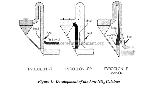
This, as it turned out, was not difficult to accomplish given the already simple design of the
Pyroclon tube calciner. A Low NO, combustion chamber can be fitted into the system
without any significant investment cost or loss of efficiency. This development is shown in
Figure 1. Similar designs had previously been used in fresh air calciners for reasons of
chemical reactive compounds in the kiln gases or for ease of retrofitting a new precalciner to
existing preheater strings.
As can be seen, the tertiary air duct now meets the calciner higher up and at an acute angle.
This arrangement allows for an increase in the Low NO, combustion zone without
significantly increasing the overall calciner height.
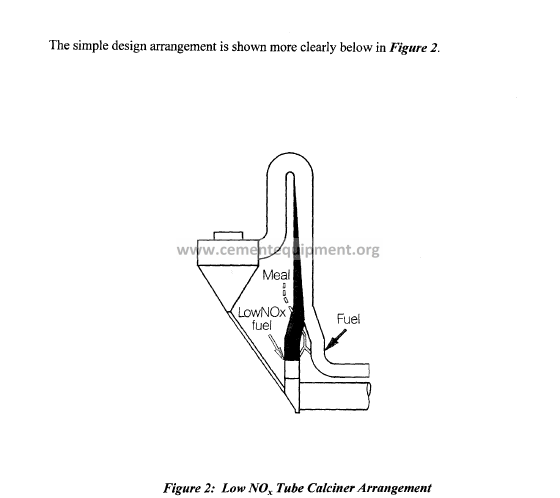
The Low NO,xcalciner has two combustion zones each with its own burner which has
different functions. The main burner injects fuel into the tertiary air flow and the, so called,
Low NO,x burner feeds fuel exclusively into the kiln exhaust gas stream. The Low NO,
burner is designed for up to 30% of the precalciner fuel rate. The kiln exhaust gas contains
the NO,x formed at high temperatures in the kiln. It also contains a low oxygen content
corresponding only to the excess air from the kiln combustion process. In this enlarged kiln
riser duct it is now possible to deliberately set up a reducing atmosphere in the kiln exhaust
gas by burning a specific quantity of fuel under sub-stoichiometric conditions. This satisfies
the first requirement for reducing the NO, content by generating partial combustible
compounds.
two streams mix gradually. The NO, therefore has a sufficient resident time in the reducing
gas phase. This fulfills another requirement for NO, reduction.
The meal to be calcined from the next to lowest stage cyclone is also divided and fed to each
of the two separate combustion zones. By metering the raw meal it is possible to influence
the temperature in the reducing kiln gas atmosphere, thereby fulfilling a third requirement for
NO, reduction.
When dimensioning the junction of the Low NOx, reaction zone and the fresh air calciner it is
important to ensure that the two gas streams have equal velocities so that the gases mix
slowly. In this design the reducing zone gases are displaced into the main calciner in such a
way that we actually have two flows in one tube calciner. As the gases flow up the calciner
the greater is the extent of mixing. The CO deliberately formed in the kiln exhaust gas duct
due to a lack of oxygen and Low NOx fuel injection, is mixed to an ever increasing extent
with the oxygen-rich gas flow from the tertiary air duct and is able to react further. Mixing
of the two gas flows takes place at the 180″ bend and the residence time of the gases in the
downward gas duct is sufficient to ensure complete oxidation of any unburned fuel particles.
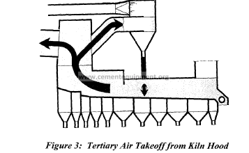
The majority of the calciner fuel is still burnt in the main calciner, the combustion of which is
significantly accelerated by the hot tertiary air, aided by the kiln hood take-off design which
ensures high gas temperature (see Figure 3).
This aspect of the Low NOx, system should not be overlooked as it is an integral part of the
process. The tertiary air temperature is increased by this method of extraction, improving
calciner fuel combustion, reducing CO emissions and giving more flexibility in Low NOx
reaction chamber operation. There is also evidence that by reducing kiln secondary
combustion air temperature this reduces k i l i i flame generated NOx
Further Development
Following on from this simple Low NO, calciner design the next development was to address
CO emissions. As already explained, the Low NO, calciner deliberately creates CO as a
main reactant to NO,. However, as a result, some installations may experience an increase in
CO emissions. This is a result of CO not totally oxidizing in the upper part of the calciner.
To avoid this situation it is essential that the available O2 in the fresh air portion of the
calciner is fully mixed with the CO created in the Low NO, chamber. To ensure thorough
oxidization of combustibles, we now install a small swirl chamber in place of the 180″ bend,
at the top of the calciner, this device is called a Pyrotop.
This arrangement is shown in Figure 4. This Pyrotop vessel is not a cyclone, just a simple
swirl chamber with a low pressure drop, as shown in Figure 5.
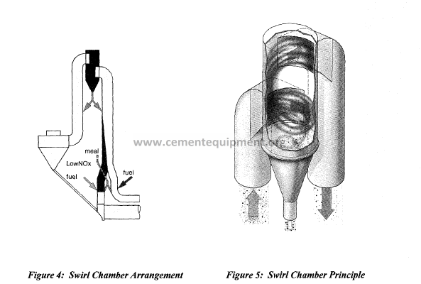
The design and location of the new chamber also enables influencing of the dust
concentration in certain areas of the calciner. The swirl chamber acts as a partial settling
chamber, approximately 10 – 15% course particle dropout may be experienced. A portion of
this dust can either be recycled back to the inlet via the ascending calciner duct or directed to
the calciner duct going to the lowest stage cyclone of the preheater (see Figure 4). In this
way we can regulate the temperature in certain zones of the calciner. In addition, particle
samples can be analyzed to determine if the dropout is coarse fuel or already calcined meal
particles, at which time it can be decided where and how much is recirculated or routed to the
calciner downcomer duct to the lower stage cyclone.
Where further reduction of NO, is necessary, this chamber is also a perfect receptacle for the
injecting of ammonia, as it offers the necessary defined “temperature window”, i.e. 850 –
950°C. By injection of NH3 or urea into this vessel in conjunction with the Low NO,
calciner virtual elimination of both thermal and fuel NO, should be feasible.
The combination of the swirl chamber and Low NO, calciner design approaches the perfect
precalciner system for today’s needs:
– Accepting all fuels
– Control of temperature profile in specific zones
– Improved mixing effect (temperature/ combustibles/ oxygen)
– Minimizing NO, and CO emissions
– Low pressure drop
– Simple operation
This type of Low NO, calciner design is currently installed in four European plants and five
more are under construction around the world. One of these is in the United States. Eight
more Low NO, calciners without Pyrotop have been installed for a total of 17 systems
worldwide to date. The technical details and operational experiences for some of these
environmentally progressive plants will now be presented.
INDUSTRIAL RESULTS
The plants reported on range in capacity from 2200 mtpd to over 5000 mtpd and include new
installations and retrofits. The results of each installation will be outlined, discussing the
specific parameters and equipment design which directly affects the extent of NO, reduction
obtained.
Dalen, Norway
Several reports have already been published on Norcem’s Dalen plant in Norway, so only a
brief overview is given. In 1988 the plant was upgraded with an additional preheater string
which was mounted above the kiln due to lack of space (Figure 6) and was equipped with a
Low NO, calciner. The gases are divided into the two preheater strings after the upper 180″
elbow of the calciner. This was the first dual strand-type Low NO, calciner installed.
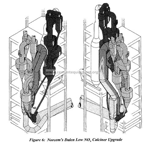
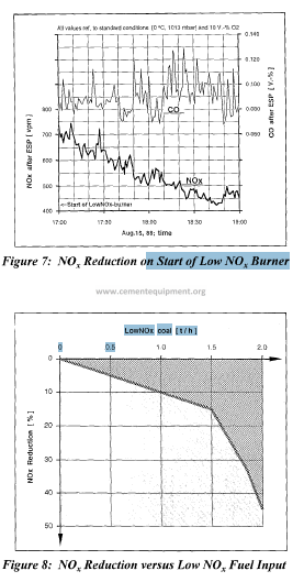
Figure 7 shows the NOx and CO
concentrations at the stack over a
period of two hours after start of
the Low Nox, firing system, i.e.
by diverting a portion of fuel
from the tertiary air strand to the
low-oxygen kiln waste-gas
combustion zone.
The continuous decrease of NOx
concentration from around 700 to
450 ppm is apparent. Although
the average CO level only
slightly increased, it is now
characterized by fluctuations
with more frequent concentration
peaks.
Figure 8 shows a summary of
the measurements taken in Dalen.
The reduction of the NOx
concentration in per cent between
kiln inlet and behind the cyclone
preheater has been plotted
against fuel mass flow at the Low
NOx burner.
The maximum reduction
amounts to 45 % during this
original test period. Note, this is
the reduction at the stack: to
achieve this the kiln generated
NOx would have to be reduced
by 60 – 70%. The additional NOx
measured at the stack is the result
of fuel NOx generated in the
upper portion of the calciner
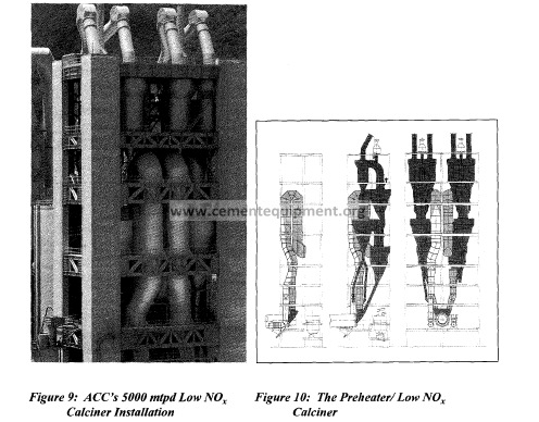
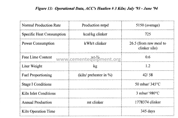
Hualien, Taiwan
ACC’s Hualien plant in Taiwan was the first new installation to incorporate a Low NO,
calciner. This was part of a new 5000 mtpd kiln line equipped with a two-tire 5 x 55 m kiln
and dual string preheater.
Figure 9 shows the installation of the two calciners of the 5000 t/d kiln system. The drawing
in Figure 10 provides different views of the symmetrical calciners, with the two cyclone
preheater strings.
In August and September 1993, systematic series of tests for NOx reduction were carried out
in this large scale plant. The diagram shows an extract from just under 8 hours. The NOx
concentration has been plotted on the left-hand scale in mg/m3 (standard reference
conditions) and the CO concentration in ppm on the right-hand scale. All values have been
standardized to a reference value of 10% oxygen. Mean values are highlighted by the
horizontal lines.
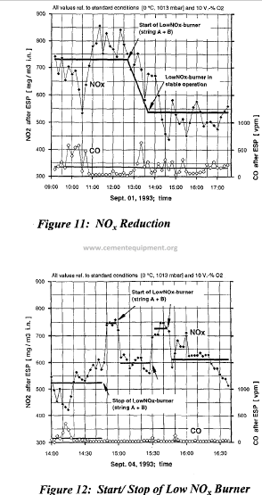
In Figure I1 the NOx values measured
at the stack reduce significantly upon
start up of the Low NOx burners in the
two calciners. The CO level is on the
whole very low in this plant and
undergoes very little change during Low
NOx operation.
Initially, CO concentration showed a
very slight tendency toward a higher
value, but still well below 0.05%.
However, subsequent operation does not
show this trend. It may be concluded the
CO fluctuations are affected more by
kiln operation, fuel and raw meal dosing
consistency than the operation of the
Low NOx calciner.
Figure 12 illustrates a test concerning
reproducibility of the reducing effect of
the Low NOx calciner. The Low NOx
burners were operated by the stop-andgo
method with the shortest switch
intervals lasting no more than 10 to 15
minutes.
The immediate reaction of the NOx
signal at start and stop of the burners is
clearly noticeable. In the course of this
test it was the basic reaction rather than
the absolute level that was of interest. It
was remarkable that during this
fluctuating test the CO concentration
remained virtually unchanged and
consistently low.
On average a 30% reduction of NO, at the stack is maintainable. The limiting factor is the
inaccuracy of the coal dosing system, which is divided in the pipeline, instead of separate
dosing systems. However, as the results for both CO and NO, are very acceptable no further
work has been done up to now.
It should be noted that the operation of the Low NO, calciner system in no way affected the
production or efficiency of the kiln system. The thermal heat consumption for this fourstage,
coal fired system averages 71 5 – 720 kcallkg. Individual performance tests have given
figures of 690 – 695 kcal/kg! The production averages 5150 mtpd, 8% over the guaranteed
value.
The guaranteed production rate of 4800 t/d was safely reached and some tests yielded
capacities in excess of 5200 t/d. The operation records (Figure 1.3) of Asia Cement taken
over a period of one year show that just under 1.8 million tons of clinker have been produced
during 345 days which means a real average of 5 150 t/d.
SDenner – Erwitte, Germany
The next plant to be reported upon is the 2200 t/day facility installed at Spenner Cement in
Erwitte, Germany. The first two-pier kiln installation combined with a precalcining system
worldwide took up operation in 1981. Since this time the short two-tire kiln has been
intemationally approved and recognized.
Early in 1993, the existing calciner was equipped with pyrotop vessel and the lower section
was modified to a Low NOx design. The kiln is operated in combination with a rotary cooler
installed below the kiln in reverse direction.
The kiln firing is operated with a
mixture of approx. 80%
pulverized brown coal and 20 YO
heavy fuel oil. The calciner and
Low Nox, burners are exclusively
run with brown coal
Figure 14 shows the preheater
tower with calciner. The newly
installed pyrotop vessel with
external weather housing can be
seen in the upper part.
A number of tests and
examinations were carried out at
this facility. They essentially
confirmed the results obtained at
the plants in Norway and Taiwan
referred to earlier. Upon startup
of the Low NOx bumer, a clear
reduction of NOx emissions of an
average of 30 to 35 YO could be
achieved at the stack, indicating a
high reduction of the NOx exiting
the kiln.
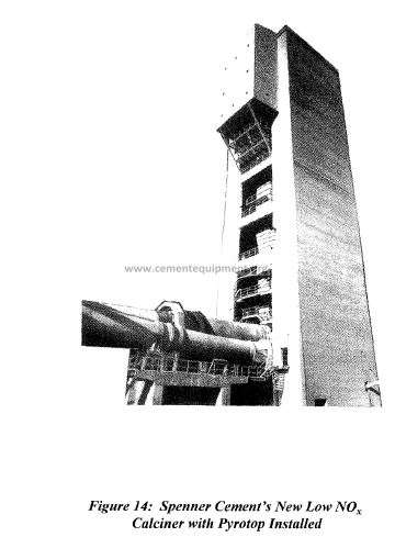
Figure 15 shows the plant
diagram in which the gas
analyzer test points at different
operational tests have been
marked. The grinding system
and E. P. are omitted.
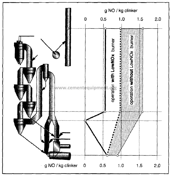
Figure 16 summarizes the
various measuring results, i.e.
from November 1993 (directly
after start-up of the new system),
from June 1994 and lastly in
March 1995. The specific
nitrogen oxide measurements are
shown in g NOx,/ kg clinker from
the kiln inlet to the stack. During
this test period the plant was
operated with and without Low
NOx burner.
Referring (again to Figure 16, the
hatched zone identifies the
fluctuating range of the results
without Low NOx operation from
the first two measuring periods.
Proportionately, the unmarked
zone defines the fluctuating
range when operated with Low
NOx burner. The two lines show
the average results of the most
recent measurements taken.
During the conventional calciner
operation, a value of up to 1.6 g
NOx/ kg clinker is measured at
the stack. With the Low NO,
calciner operation, this is reduced
to 0.9 g NOx/ kg clinker, a 45%
reduction.
During Low NO, operation, the actual value ranges from 0.6 to 1 .O g NO,/ kg clinker. During
the most recent measurements made in March 1995, the emission at the stack showed a
further reduction to less than 0.6 g NO,/ kg clinker, a 65% reduction.
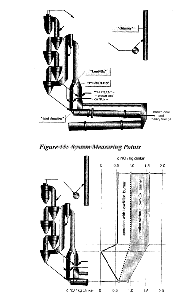
Figure 16: Summary of Results
In contrast to the situation at Hualien where the CO level on the whole was very low, the CO
concentration in the flue gases increased in this plant during Low NOx, operation. Although
the gases contain less than 1000 ppm CO, a typical range of many plants, they are almost
twice as high compared to the conventional Humboldt tube type calciner operation.
This phenomenon is partially attributed to pronounced metering inaccuracies of the three coal
dosing units, in particular that for the Low NOx, burner.
Despite this variable, the measurements diagramatically shown in Figure 16 indicate an even
further optimization potential. Based on a value of 0.6 g NOx,/ kg clinker in the kiln inlet
chamber, (this figure is determined by kiln firing), no NO, could be detected during Low
NOx, operation at the exit of the Low NOx, reaction chamber. This represents a measured
value of 100% reduction of the kiln generated NOx,.
On the other hand, it should be mentioned that measured values almost as high values as in
the kiln inlet chamber have been detected behind cyclone 5 and at the stack. Consequently,
this NOx, emission is due mainly to the formation of fuel NOx, in the oxidizing part of the
calciner and may be in part due to secondary combustion reactions of the Low NOx, gas
strand. This is another potential area for further optimization. by the consideration of
alternative burner positions and tertiary-air routing, and by improving fuel mixing and
combustion efficiencies in the calciner.
Summarv of the Results
Generalizing the results for each of the plants discussed, it is clear that the use of a Low NOx,
calciner has been a success for the three plants reported upon. Whether with or without
pyrotop, with two- or three-pier kiln, with rotary or grate cooler, all three installations have
one feature in common. The NOx, emissions at the stack were significantly reduced.
In all cases the NOx, emissions declined with increased fuel quantity a.t the Low NOx, burner.
Unfortunately, all of the plants suffered from less than perfect coal dosing systems,
particularly in relationship to the dosing of fuel to the Low NOx, burner. This limits the
opportunity to determine the maximum benefit for a given Low NOx, reaction zone size.
It is, therefore, of vital importance that the Low NOx, fuel source have its own, accurate
dosing system.
In all cases the NOx, was reduced 30 to over 50% at the stack, given the fuel NOx, still
generated in the calciner itself, the actual reduction of kiln exit NO, is in the range of 50 to
possibly 100%.
Operationally, there are no negative effects on production or thermal efficiency . Calcination
rates are as high as normal calciner values. Reducing gas atmospheres can sometimes result
in higher coatings in the calciner, but this was only really experienced at one plant, which
anyway had a history of heavy coating that only slightly increased in the Low NOx, reaction
zone. The ability to control the temperature in this area of the Low NOx, calciner by metering
raw meal helps relieve this potential problem.
CO emission may increase slightly with high levels of NOx, reduction, but they may be
controlled to normal or even lower values by the use of a Pyrotop type swirl chamber.
Many new installations of Low NOx, calciners are now coming on line throughout the world,
the experience gained from these installations is being transferred, so that optimum NOx,
reduction via this new calciner technology can be truly determined.
New Installations Incorporating the Current State of Technolom
As previously mentioned, there are many new installations now incorporating this new
calciner technology. Two notable installations will be briefly discussed and their unique
features outlined.
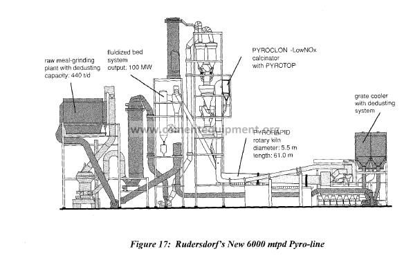
The largest Low NOx, precalciner system is presently installed at the Rudersdorf plant of the
Readymix Group in Germany. The 6000 mtpd kiln line system includes a fully integrated
Low NOx, calciner and a Pyrotop swirl chamber. The main equipment data can be seen below
in Figure 17. Of additional interest is the fluidized bed combustion chamber to allow
various waste fuels to be burned and the hot gases to be used in the calciner. The ash
developed is then used as components of the raw mix. The operation data from this modem
plant is scheduled for presentation at the 1998 IEEE meeting; therefore, will not discuss it
further at this time.
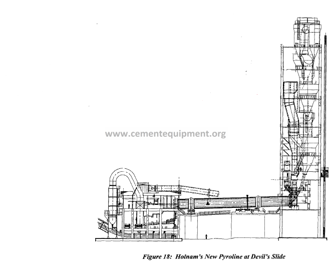
Here in the USA, Holnam’s new production line at the Devil’s Slide plant is under
construction.
This new kiln line, near Salt Lake City, Utah incorporates all the best available technology
for control of combustion emissions. This includes a Pyrojet burner, short kiln technology
for rapid clinkerization kiln hood tertiary air takeoff and a Low NOx, calciner equipped with a
Pyrotop swirl chamber (see Figure 18 below).
The Low NOx, portion of the calciner will be fired with tire-chips and other high volatile solid
waste fkels. The Low NOx calciner may also be fueled with coal which has its own separate
and accurate dosing system. The amply designed Low NOx, reaction chamber and available
methods of fuel injection promise to make this new installation a model for Low NOx,
calciner operation. Installed in this way the optimum NOx, reduction capabilities should be
reached by the calciner system at this plant. Startup is scheduled for end of this year.
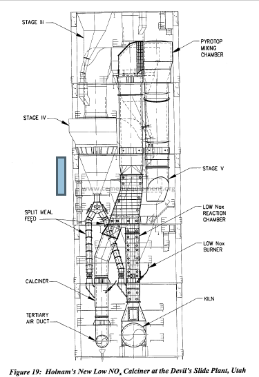
The arrangement of Holnam’s new Low NOx, calciner is shown
on Figure 19. The calciner also includes a Pyrotop vessel of a
new design. As one may notice this swirl chamber
incorporates the calciner downcomer duct as its lower part in
place of a collection cone. In this way no particle dropout is
experienced, yet the required mixing of reaction gases is
efficiently achieved. The selection of dropout swirl chamber or
this type of swirl duct design will depend upon fuel types,
arrangement of Low NOx, calciner and chemical composition of
raw materials.
Also in Figure 19, one can clearly see the distribution of fuel
and raw meal between the two calciner combustion chambers.
The raw meal is split below stage IV cyclone in a specially
designed, remotely actuated splitter gate.
Conclusion
As demonstrated by the operating systems outlined in this paper, Low NOx, calciner
technology is no longer a concept but a reality.
The amount of knowledge now becoming available as a result of the multiple systems
coming on line will enable us to refine the calciner design further. It seems apparent that
when correctly applied, this technology can achieve up to 100% decomposition of the NOx,
generated in the rotary kiln.
The good news for producers is that the installation cost of this type of calciner is not
significantly higher than that of regular type calciners. The main additional cost is related to
the additional fuel dosing system. Existing tube calciner installations may also be modified
to incorporate some extent of NOx, reduction.
For new installations it seems clear that all future plant designs should include a Low NOx,
calciner.