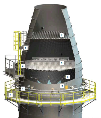
Quick answer
Gas-conditioning-tower outlet temperature oscillation is usually a water-spray/atomization/control problem until proven otherwise. The GCT removes heat by evaporating injected water, so unstable outlet temperature can follow erratic water flow, poor atomization, nozzle fouling, unstable atomizing-air pressure on twin-fluid systems, valve hunting, changing inlet gas flow/temperature, or a bad outlet-temperature signal. Diagnose the loop by trending inlet temperature, outlet temperature, spray-water command and actual flow, atomizing pressure where applicable, ID-fan/load condition and hopper wetness at the same time.
Problem / job
Gas Conditioning Tower Outlet Temperature Oscillation is occurring repeatedly or outside the expected operating pattern and requires a cause-based diagnosis rather than trial-and-error adjustment.
Evidence
Capture GCT inlet/outlet temperatures, water-flow command and actual flow, control-valve position, pump pressure, atomizing-air pressure for twin-fluid nozzles, ID-fan/load condition, nozzle maintenance history, hopper condition and the timing of each oscillation.
Decision
Separate measurement error, changing gas heat load, unstable water delivery, poor droplet atomization, control-valve/PID hunting and incomplete evaporation. Do not tune the controller until the temperature signal and spray hardware are proven mechanically stable.
As-found evidence capture
Before tuning the GCT loop, trend inlet-gas temperature, outlet-gas temperature, water-flow command, actual water flow, control-valve position, spray-pump pressure, atomizing-air pressure where applicable, ID-fan/load condition and hopper wetness on the same time base. Note whether the oscillation follows mill on/off changes, kiln load changes, valve movement, pump cycling or an individual spray-lance event.
Record the last nozzle/lance inspection, water-filter condition, pump maintenance, temperature-probe calibration and any change to controller tuning. At the next safe inspection document nozzle fouling or wear, spray-pattern irregularity, wet wall/hopper deposits and evidence of incomplete evaporation before cleaning the system.
Field checklist before tuning the GCT loop
- Verify outlet-temperature measurement with the plant-approved reference or redundant indication.
- Trend inlet temperature, outlet temperature, water command and actual water flow on the same time base.
- Check spray-pump pressure and control-valve movement for sticking or hunting.
- For twin-fluid systems, trend atomizing-air pressure and confirm it is stable during the event.
- Inspect nozzle/lance condition and recent cleaning history; fouling or erosion can change droplet quality.
- Check hopper condition for wet dust, mud or signs of incomplete evaporation.
- Only after hardware and measurement are stable, review controller tuning and deadband.
Seven-step diagnostic workflow
1. Correlate the temperature oscillation with spray demand and gas heat load
Trend inlet and outlet gas temperatures together with commanded and actual spray-water flow, valve position, pump pressure, atomizing-air pressure where fitted, ID-fan/load condition and mill/kiln operating state. Determine whether the outlet temperature swings because the heat load itself is changing or because the cooling system is failing to deliver a stable evaporation rate.
2. Verify the outlet-temperature measurement before tuning
Cross-check the outlet-temperature probe against the plant-approved reference or redundant indication. Inspect probe location, buildup, wiring and calibration history. A lagging or biased probe can make a stable spray system appear to hunt and can drive unnecessary PID or water-flow changes.
3. Prove water delivery rather than trusting the command
Compare commanded spray-water flow with the actual measured flow and pump pressure. A control valve can move while flow remains unstable because of sticking, recirculation, suction problems, plugged strainers or changing pressure. If outlet temperature oscillates in phase with real water-flow oscillation, solve the hydraulic instability before retuning the temperature controller.
4. Check atomization quality and nozzle condition
Inspect spray lances/nozzles according to the plant isolation procedure. Hydraulic and twin-fluid systems depend on droplet formation for complete evaporation. Nozzle fouling, wear, incorrect pressure or unstable atomizing air can shift droplet size and evaporation time, producing alternating overcooling and undercooling even when average water flow looks reasonable.
5. Separate gas-load changes from spray-system faults
Trend inlet gas temperature, ID-fan speed/current, kiln or mill operating mode and gas flow indicators. If the GCT inlet heat load changes sharply, the outlet controller may simply be chasing a moving process. If inlet conditions are stable while outlet temperature swings, focus more strongly on measurement, water delivery and atomization.
6. Check for incomplete evaporation and hopper wetting
Inspect hopper and dust-discharge evidence for damp material, mud or buildup. Wet dust is evidence that liquid residence time, droplet size, gas distribution or water rate may be outside the intended operating envelope. Correct the physical evaporation problem before increasing spray rate or tightening controller response.
7. Prove the correction under representative load
After the identified cause is corrected, repeat the operating condition that previously generated gas conditioning tower outlet temperature oscillation. Record the same evidence set before and after the intervention. Acceptance requires repeatable stability, not a short period with the symptom temporarily absent.
Evidence-to-decision table
| Observed evidence | Most useful next check | Decision direction |
|---|---|---|
| Outlet temperature oscillates in phase with actual water-flow oscillation | Control valve, pump pressure, strainers and hydraulic stability | Fix water-delivery instability before PID tuning |
| Water flow is stable but outlet temperature still swings | Nozzle pattern, atomizing-air pressure, gas distribution and probe response | Investigate atomization/measurement rather than flow command |
| Outlet swings only when inlet temperature or gas flow changes sharply | Kiln/mill operating mode, ID-fan/load and controller feed-forward/response | Treat a moving heat load rather than a spray-hardware fault |
| Wet hopper or wall deposits appear during oscillation | Droplet size, lance/nozzle condition, spray distribution and evaporation distance | Reduce incomplete evaporation; do not simply add more water |
| Twin-fluid system oscillates with unstable atomizing air | Air pressure, valves, compressor/supply stability and nozzle condition | Restore atomization stability before controller tuning |
| Probe disagrees with redundant/reference temperature | Probe fouling, location, calibration and signal lag | Repair measurement before changing spray settings |
Verification and return-to-service criteria
Accept the GCT loop when outlet temperature remains stable through representative kiln/mill operating changes, actual spray-water flow follows demand without hunting, pump/valve behavior is repeatable, atomizing-air pressure is stable where applicable, spray nozzles/lances are in acceptable condition, and no wet hopper or wall buildup indicates incomplete evaporation.
Use the installed GCT, nozzle and downstream dust-collector OEM limits for temperature, water pressure/flow, atomizing air and moisture constraints. Do not invent universal outlet-temperature or spray-pressure limits because the correct values depend on gas flow, inlet temperature, tower geometry and downstream equipment.
Common mistakes and repeat-failure traps
Do not retune the PID before proving the temperature signal, water-flow measurement and spray hardware. Do not trust valve position as proof of actual water flow. Do not compensate for a fouled or worn nozzle by simply increasing water. Do not ignore atomizing-air instability on twin-fluid systems or wet hopper deposits that prove incomplete evaporation. Finally, do not declare success until the same kiln/mill operating condition has been repeated with stable outlet temperature and dry downstream operation.
Build a stronger cement maintenance library
The Infinity for Cement Organization technical package contains 900+ technical files for cement professionals. It is a one-time $249.99 purchase, with instant download immediately after payment and lifetime updates forever at no additional cost.