Contents
Everything you need to know about Thermal Energy Efficiency in Cement Industry
SECTION 1
Useful formulae, Model calculations, norms & CFD
Chapter – 1
Preheater
1.1 Spray cooling of gas1:
Amount of Water spray for cooling gas can be calculated as mentioned below:
Water t/h = Q.ρ.S.∆T/[(100-Tw)+539)]
Where
Q = gas flow Nm3/h
ρ = gas density Kg/Nm3
ΔT = gas cooling, 0C
S = specific heat kCal/Kg 0C
Tw = water temperature 0C
1.2 Oxygen concentration at Preheater exit (for Preheater without
air lift feeding)
Oxygen concentration at preheater exit to be maintained during steady
state running of the Kiln : 2.5 to 3% O2
Oxygen concentration at Kiln inlet : 1.5 to 2% O2 (dry) CO < 0.01%
Target false air across Preheater tower : 5% of Preheater gases by
volume or 1% increase in O2
content
1.3 Separation efficiency of top stage cyclone : 92 –95 %
1.4 Gas Residence time in Precalciner:
Typical residence time of gas in precalciner for different fuels: 3-5 sec
1.5 False Air:
Air leakage through an aperture of area A (m2) with pressure differential
dP (mm H2O) can be approximately calculated from
Volume (m3/hr) = 8900 X A X dP0.5
Air leakage between two points in the kiln exhaust system can be
determined by oxygen measurement.
False air (in terms of outlet) % = 100 (G2-G1)/(20.9-G2)
Where G1 = initial O2 %
G2
= final O2 %
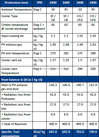
1.6 Typical heat balance of ILC kilns with Six-stage preheater:
1.7 Effect of false air on heat consumption:
Effect of false air on heat consumption in a five stage preheater for
0.5% increase in cyclone exhaust O2
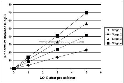
1.8 Effect of incomplete combustion (CO) in Pre Calciner:
Effect of incomplete combustion in Pre calciner in a 5 stage pre heater
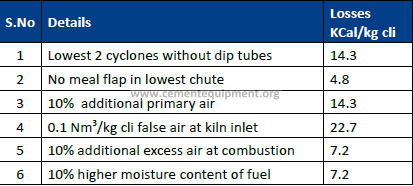
1.9 Effects of improvements/losses of Kiln System:
Improvements/losses in kiln system
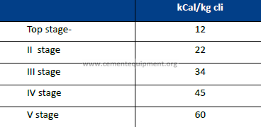
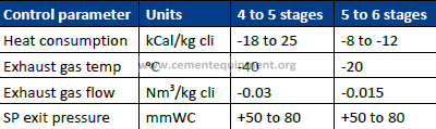
1.10 Effect of stage addition in Preheater:
Chapter – 2
Kiln
2.1 Kiln burner performance:
Primary air momentum is calculated (% m/sec):
% m/s = Lp % x C
Where :
Lp : The primary air % of the total minimum air requirement for
complete combustion of fuel fired in Kiln.
C : Primary air velocity at the burner nozzle
For a multi channel Burner:
Flame momentum of a multi channel burner when primary air is divided
into axial air and radial air :
Total flame momentum flux = Axial air momentum flux+
Radial air montum flux
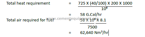
Model calculation:
Clinker production = 200 TPH
Specific Heat consumption = 725 kCal/kg clinker
Fuel fired in Kiln burner = 40% of total fuel
Primary air = 9270 m3/hr at 300C
Net calorific value of fuel = 7500 kCal/kg coal
Theoretical air required for
1 kg of fuel firing = 8.1 Nm3/kg of fuel
Air Channel Cross Section Areas:
Axial A1 = 0.0101 m2
Radial A2 = 0.0075 m2
Air flow at Burner tip:
Axial A1 = 9270 X 0.9 X 0.65
= 5425 m3/hr at 300C
= 5397 Nm3/hr
Radial A2 = 9270 X 0.9 X 0.65
= 2920 m3/hr at 300C
= 2754 Nm3/hr
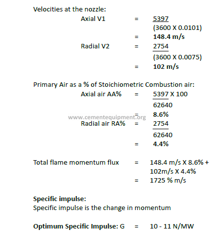
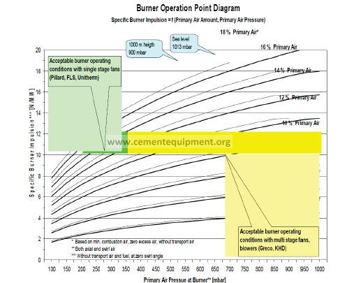
2.2 Kiln burner optimum design2:
Range of Kiln Burner Primary air momentum:
(with 6 to 8% primary Air) : 1250 to 2000 % m/s
(Primary Air as a % of Stoichiometric Combustion air)
Optimum Kiln Burner Primary air momentum:
(with 6 to 8% Primary Air) : 1400 to 1600 % m/s
(For strong, stable, short and narrow flame)
Lower Primary Air Momentum causes longer flame & high kiln shell
temp in burning zone area, high kiln backend temperature, extended
burning zone & lower burning zone temperature.
2.3 Main Burner solid fuel loading and injection velocity at burner
tip :
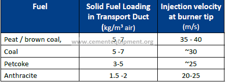
– Feed of solid fuel (kg/s) divided by the transport air flow in duct
(m3/s)
– Transport velocity of solid fuels in the transport duct: >25 m/s
(acceptable)
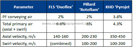
2.4 Burner specification :
Volume flow of transport air (m3/s) at burner tip temperature divided by
the area of the solid fuel injection channel at the burner tip.
Typical specifications used by vendors for burners with indirect firing
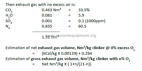
2.5 Kiln Exhaust Gas (Coal) calculation3:
Assume a typical bituminous coal with ultimate analysis (as dried basis)
C 80.0%
H 5.0
S 1.0
O 5.0
N 0
Ash 8.0
Net kCal/kg 7400
with indirect firing and specific fuel consumption of bituminous coal
0.127 kg/kg clinker. Combustion gases produced can be calculated as
under:
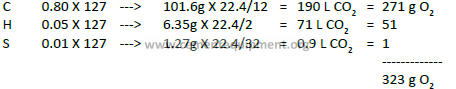
Then added O2 required for combustion = 323g – 6.35g = 317g = 222 L
Or 0.222 Nm3
Then equivalent N2 from air = 222 L X 79/21= 835 L
Or 0.835 Nm3
CO2 from calculation of raw meal to yield 1kg clinker (assuming kiln feed
LOI of 35%)
((1000/0.65)-1000) =539 g = 274 L or 0.274 Nm3
Then total CO2 in exhaust gas = 274L+190L = 0.464 Nm3
H2o from Kiln feed (assuming 1.65 Kiln feed: clinker factor and 0.5%
H2O)
1 kg X 1.65 X 0.005 = 8.25 g = 10 L or 0.01 Nm3
2.6 Gas velocities4:
Upper limits and lower limits of Gas velocities at different areas in Pre
heater, Kiln and cooler are given below:
a) Upper Limits:
m/sec
Through Cooler grate 10
Hood 6
Under Cooler bull-nose 15
Burning zone (14500C) 9.5
Feed end transition (10000C) 13
Riser 28
Preheater gas ducts 15
b) Lower Limits:
m/sec
Tertiary duct 30
Pulverized Coal conveying 25
2.7 Kiln thermal loading5
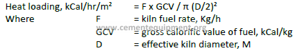
Standard heat loading values:
LD (long dry kiln) 1.2 kCal/hr/m2
SP (Preheater kiln) 2.0
AT (air through Precalciner) 3.0
PC (Precalciner) 4.0 to 6.0
NPC (New Precalciner) 5.0 to 6.0
Chapter -3
Cooler
3.1 Grate Cooler :
-Specific grate area loading < 45 t/d m2
(Daily clinker production (t/d) / total active grate surface area
(m2)
-Specific grate width load < 1250 t /d m (Preferred)
< 1500 t/d m (Maximum)
(Daily clinker production (t/d) divided by grate width (m))
-Grate speed : 10 – 15 str/min
Typical grate speed in strokes/ minute (higher speed means higher
grate wear)
Installed specific cooling air volume < 2.0 Nm3/Kg cli (for new coolers)
< 2.5 Nm3/Kg cli
(for old coolers)
installed cooling air volume (Nm3/h) / hourly clinker production
(Kg/hr)
-Vent air take off velocity < 5 m/s For new installations
< 6 m/s For old installations
-Tunnel velocity < 10 m/s
(horizontal air velocity towards air extraction locations)
Exact calculation of the tunnel velocity is difficult. Rough
estimations can be made using cooling air distribution together
with cooler drawings and an estimation of air temperature at the
respective location.
3.2 Cooler recuperation efficiency:
Cooler efficiency E % = (C1 – (V+C2+R))/ C1
Where
C1 = heat content of clinker from kiln
C2 = heat content of clinker out
V = heat content of cooler vent air
R = Cooler radiation
Typical efficiencies:
Conventional Grate cooler 60 – 70%
Air beam 70 – 75%
Latest generation cooler 75 – 78%
Chapter – 4
Raw Meal & Fuels
4.1 Solid fuel heat value6:
Gross heat value kCal/Kg = 80.8 C + 22.45 S + 339.4 H -35.9 O
Net heat value, kCal/kg = 80.8 C+22.45 S + 287 (H-O/8) – 6 W
Where W is H2O content, %
Gross – Net = 51.5 H*
Where H* is total % H2 including H2O
(Gross heat is the theoretical heat of combustion which assumes that
water produced is condensed. In practice, water is usually released as
vapour so that only Net Heat is recovered).
4.2 GCV & NCV of various fuels
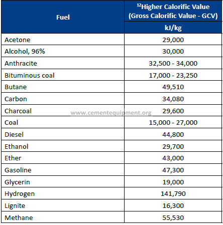
• 1 kJ/kg = 1 J/g = 0.4299 Btu/ lbm = 0.23884 kCal/kg
• 1 kCal/kg = 4.1868 kJ/kg = 1.8 Btu/lbm
• 1 dm3 (Liter) = 10-3 m3 = 0.03532 ft3 = 1.308×10⁻³ yd3 = 0.220 Imp gal
(UK) = 0.2642 Gallons (US)
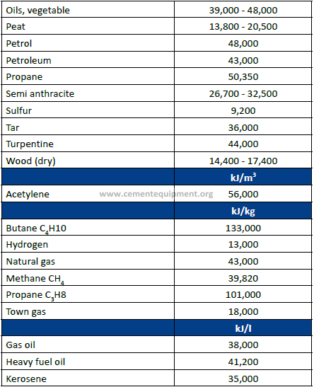
Typical Data for Solid Fuels (% as recd/mineral-matter-free):
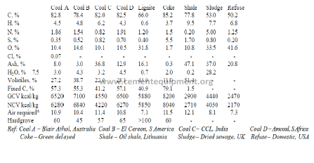
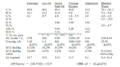
Typical Data for Liquid Fuels:
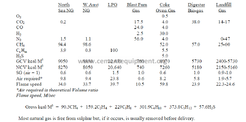
Typical Data for Gaseous Fuels:
Liquified gases yield the following:
1 L liquid
Methane – 606 L gas
Propane – 139 L gas
Butane – 119 L gas
4.3 Clinker Constituents
1. If alumina modulus > 0.64
C3S = 4.071 CaO – 7.602 SiO2 – 6.718 Al2O3
– 1.43 Fe2O3 – 2.852 SO3
C2S = 2.867 SiO2 – 0.7544 C3S
C3A = 2.65 Al2O3 – 1.692 Fe2O3
C4AF = 3.043 Fe2O3
2. If alumina modulus < 0.64
C3S = 4.071 CaO – 7.602 SiO2 – 6.718 Al2O3
– 1.43 Fe2O3 – 2.852 SO3
C2S = 2.867 SiO2 – 0.7544 C3S
C3A = 2.65 Al2O3 – 1.692 Fe2O3
C4AF = 3.043 Fe2O3
2. If alumina modulus < 0.64
C3S = 4.071 CaO – (7.602 SiO2 + 4.479
Al2O3 + 2.859 Fe2O3 + 2.852 SO3)
C2S = 2.867 SiO2 – 0.7544 C3S
C3A = 0
(C4AF + C2F) = 2.1 Al2O3 + 1.702 Fe2O3
4.4 Coating tendency7
Coating tendency = C3A + C4AF + 0.2 C2S + 2Fe
Note index < 28 indicates light coating
> 30 indicates heavy unstable coating, rings & snow men4.5 Burnability factor8:
4.5 Burnability factor8:
Miller’s empirical formula for burning at 14000C
% Free- lime1400 =0.33 (%LSF–100)+1.8 (S/R-2)+0.93Q+0.33C+0.34A
Where Q = +45μ residue after acid wash (20% HCl)
Identified by microscopy as quartz
C = +125μ residue which is soluble in acid
(ie calcite)
A = +45μ residue after acid wash identified by microscopy
as Non – quartz acid insoluble
4.6 Required burning temperature9:
Required burning temperature maintained for reaction of raw meal
constituents to form clinker
Burning temperature, 0C = 1300 +4.51 C3S + 3.74 C3A-12.64 C4AF
4.7 Heat of Reaction :
The amount of heat required (kCal) to form 1 kg of clinker from kiln
feed
Q = 4.11 Al2 O3+ 6.48 MgO + 7.646 CaO – 5.116 SiO2 – 0.59 Fe2O3
4.8 Conversion factors Calculation
Raw meal to clinker factor:
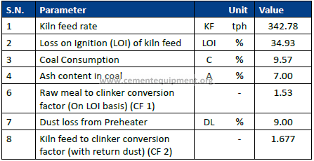
Raw meal to clinker factor = (1- (C x A)/104)/ (1- LOI/100)
Kiln feed to clinker factor = Raw meal to clinker factor/ (1- DL/100)
4.9 Raw materials:
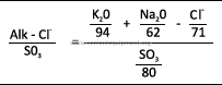
4.9.1 Alkali bypass:
Concrete was damaged in cases where alkali content of the cement was
more than 1%. Highest admissible alkali content in cement is 0.6%. with
a slag component of atleast 50% can have maximum alkali content of
0.9%. further total alkali of limit of 2% is allowed for cement with slag
component of atleast 65%.
K2O condensation rate in Preheater – 81 – 97%
Na2O condensation rate in Preheater – 3 – 19%
More than 25% kiln bypass volume has negative impact on the Kiln heat
economy. It yields relatively low alkali reduction. In most cases 3-10%
bypass volumes are sufficient. Increase in heat consumption about 4-5
kCal/kg clinker for 1% bypass volume. Additional energy consumption is
about 2kWh/Ton of clinker.
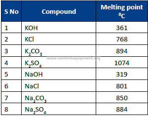
4.9.2 Melting point of various alkali compounds:
4.9.3 Required grinding fineness of coal :
Coal is to be grounded finely to fire in the kiln, the required residue on
90 μm and 212 μm as below:
% R 90 μm ≤ 0.5 * (% volatiles)
% R 212 μm ≤ 2%
4.9.4 Required grinding fineness of pet coke:
Pet coke has to be grounded finely compared to coal. Typical fineness
could be as below:
% R 90 μm ≤5 %
% R 212 μm ≤1 %
4.9.5 Required grinding fineness of pet coke/ Coal mixture:
%R 90 μm ≤ (coal fraction)*0.5*(% volatiles) + (petcoke fraction)*5%
%R 212 μm ≤1 %
Alkali to sulphar ratio of clinker: 0.8 – 1.2 acceptable range
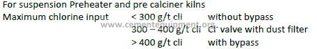
4.9.6 Maximum chlorine input:
4.9.7 Apparent decarbonation of the hot meal:
92-96% for PC systems
30-60% with secondary firing
10-40% for PH systems
4.9.8 Silo Homogenising Factor
for finding efficiency of homogenising silo we use the term homogenising
factor, which is the ratio between inhomogenity before and after silo.
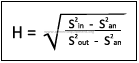
Where
H = Homogenising factor
Sin = the standard deviation of one chemical parameter in
the feed to the silo
San = standard deviation attributable to analysis
Errors / Standard deviation of the sampling
And analysing process (measuring fault)
Sout = the standard deviation of one chemical parameter in
the discharge from the silo
Chemical variation of input
Obtained result:
Sin = 0.70% Cao
Sout = 0.10% Cao
San = 0.03% Cao
Homogenising factor = 7.3
Chemical variation of output
When the true homogeneity of the kiln feed is less than 1% LSF,
corresponding to 3% C3S, 0.2% CaCO3 or 0.1% CaO then there is no
further improvement in kiln operational stability or cement quality can
be achieved through additional homogenization.
In order not to exceed this level of kiln feed in homogeneity, an H-factor
of order of 5-10 is usually required, but it must be considerably higher
under adverse conditions.
In the modern silo in practice the Homogenising factor of 10 – 20 is can
be achieved.
Chapter 5
Computational Fluid Dynamics
5.1 Introduction
Computational fluid dynamics (CFD) is one of the branches of fluid
mechanics that uses numerical methods and algorithms to solve and
analyze problems that involve fluid flows. Computers are used to
perform the millions of calculations required to simulate the interaction
of fluids and gases with the surfaces used in engineering. CFD analysis
could be employed to pinpoint high pressure drop zones in ducts.
CFD Predicts fluid flow with the complications of simultaneous flow of
heat, mass transfer, phase change and chemical reaction, etc. using set
of certain CFD softwares and calculations.
Most of the plants designed using the past technology or the needs at
that time are operating close to its design limits in the current scenario
as there is increase in the demand. With the rapid advancement in
computers, Computational fluid dynamics is used across the world in
all industries for validating designs, troubleshooting, maintenance and
upgrading so that they operate safely and at peak efficiencies with
optimum cost.
Benefits in Cement Plants
CFD study was conducted to pinpoint high pressure drop zones in ducts
& cyclones by several cement plants. Benefits from CFD study are
encouraging and are summarized below.
-Increase in top stage cyclone efficiency results in reduction in exit
temperature
– Uniform gas flow and material distribution
– Reduction in pressure drop across cyclone
CFD applications belt processes by simulating and analyzing them so
that it can be optimized the use of materials, tools, shape, time and
most important Energy and Cost.
Duct, Cyclones, Preheater, Kiln, Coolers, Piping, Can be analyzed and
improved upon by using correct CFD techniques.
Efficiency Improvements: Revisiting the Cyclone design can be a driver
for higher collection efficiencies.
Pressure Drop Reduction: Revisiting the ducting and Cyclone designs
can be a big driver for reduction in Pressure drops and there by Energy Savings.
The key benefit of CFD is it saves Time and Money as it is “Simulation
Based Design” in stead of“Build and Test”
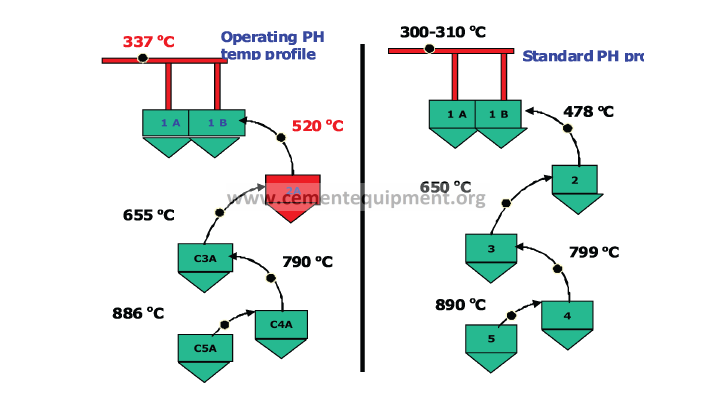
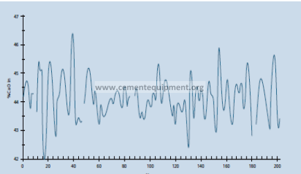
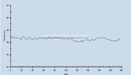
5.2 Pre heater exit temperature reduction :
Pre heater exit temperature in Cement plants is higher than the standard
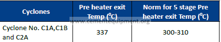
value during the steady operation also. In a plant It was observed that
Pre heater exit temperature is 3370C, which is high. The recommended
PH exit temperature is 3100C for similar stage Pre heater. This indicates
that temperature drop of 270C is occurring in less. Heat loss is happening
due to high Pre heater exit temperature.
The schematic and of the pre heater temperature profile:
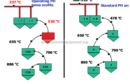
From the above figure Cyclones with lesser temperature drop and :
General reasons for high PH exit temperature:
– High excess air
-High return dust (low cyclone efficiency)
-High velocity and improper material distribution
Good energy saving potential prevails by reducing the PH exit temperature
and thereby reducing the specific thermal energy consumption.
Benefits:
Depending upon margin available, Reduction in heat consumption
about 5-20 kCal / kg clinker possible.
5.3 Minmising dust loss from Pre-heater by improving top stage
cyclone efficiency:
Pre heater exit losses play a major role in specific thermal energy
consumption of the plant. In prehaeter exit loss is divided into preheater
exist gas loss and preheater exist dust loss.
Pre heater dust losses depend on the efficiency of top stage cyclone.
Modern cement plants are operating with top stage cyclone efficiency
of about 95-97%. If the efficiency of the preheater system is <90% then
there is a good saving potential exists by minimizing dust losses from
preheater.
In a plant the schematic of dust losses given below:
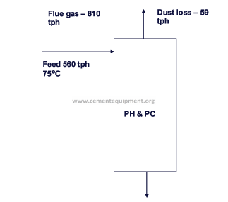
From the figure it is observed that the Preheater dust losses are around
10.5%. Excellent opportunity in reducing dust loss through CFD analysis
or retrofitting of topstage cyclone. Positive results on dust loss reduction
without increasing pressure drop of the cyclone has been successful in
several Cement plants.
Benefits:
Reduction in thermal energy consumption about 2-5 kCal / kg clinker
possible.
CFD Implementation Time
Time required to complete CFD study by supplier is depends upon the
size and complexity of the problem can vary between 4 to 16 weeks.
However, Cement Plant requires 2-3 days of shutdown for implementing
this project i.e the installation of flow diverter plates inside the ducts.
The major steps involved include:
1. Site Visit and data Collection and verification
2. Phase 1:
-3D Model generation
-Mesh generation
– Solution
-Post Processing/ Validation
3. Phase 2 : (Design Modifications)
♦♦ 3D Model modifications based on CFD results
♦♦ Mesh generation
♦♦ Solution
♦♦ Post Processing
SECTION 2
Case Studies
Chapter 6
Thermal Energy Saving Opportunities
In Cement Plant
6.1 Lower dispersion box height in riser duct and increase heat
transfer in Preheater
The Preheater system is one of the major areas for potential reduction
in thermal energy consumption in the plant. The main aim of the PH
system is to recover maximum heat from the kiln exhaust gases and to
reduce overall thermal energy consumption.
In Preheater System, the overall system is counter current, whereas
stage wise is a co-current heat exchange system.
Maximum heat transfer between the kiln feed & calciner exit hot gases
takes place in the riser ducts. In the Preheater cyclones, the separation
of feed material and hot air takes place. The feed material is then fed
to the lower cyclone and the hot air moves to the higher elevation
cyclone.
Almost 80% of the entire heat transferred from the hot gases to raw
meal is in riser ducts. To ensure maximum heat recovery in the riser
ducts, the feed pipe from the higher stage should be lowered as much
as possible.
This increases the heat transfer between the hot gases and feed material
in each stage, before they are separated in the cyclone. This will result in
lowering of exit gas temperatures from the PH system.
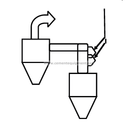
The optimum point of feed inlet to the riser duct is at 1.0 m height from
the cyclone top.
The lowering of feed pipes as shown in the Figure in the identified
cyclones of Preheater would result in a reduction of at least 5 – 100C
reduction in Preheater gas exit temperature.
Most of the Cement plants modified the dispersion box height and
reduction in their Preheater exit temperature is observed.
Benefits:
Thermal energy savings: 2 – 5 kCal/kg clinker reduction in the thermal
energy consumption of the plant.
6.2 Multi channel burner in place of conventional Burner:
Conventional Burner:
For a conventional burner Primary Air supplied for combustion of Coal
is 15 to 20% of total theoretical air required for combustion (i.e high
primary air to theoretical air ratio).
Disadvantages:
-It offers very little flexibility of operation
-The exit speed obtains a fixed velocity at the tip of the burner
by design of the nozzle velocity. The velocity cannot be adjusted
during operation.
– The shaping of flame by changing the burner adjustment is also
not possible during the operation e.g. in order to optimise the
temperature profile in the sintering zone.
– This will not help the kiln operator as necessary “tool” to quickly
stabilize any upset conditions.
Multichannel Burners:
Latest plants have Multi channel Burners for similar application.
Latest multi channel Burners have following advantages compared to
Conventional mono channel Burner.
-Multi-channel burners offer better flame shape control because
of their separate primary air channels, allowing for adjustment of
primary air amount and injection velocity independently of the
coal meal injection.
-The most important flame control parameters are primary air
momentum (primary air amount multiplied by discharge velocity)
and amount of swirl (tangentially air discharge).
-A high momentum will give a short, hard flame whereas a low
momentum will make the flame longer and lazier. Swirl will help
creating recirculation in the central part of the flame. This will
stabilize the flame and give a short ignition distance. Too much
swirl however can cause high kiln shell temperatures due to flame
impingement on the burning zone refractory. A good swirl control
system is therefore important. The best solution would be a system
where swirl could be adjusted independent of the momentum.
Most modern multi-channel burners therefore have adjustable air
nozzles.
– Require lower primary air volume. Multi-channel burner offers
to fire Alternate fuels like liquid, solid, bio-mass and to achieve
thermal substitution rates.
-Advanced technology burner always reduces the loss in production
during kiln disturbances and also reduces NOX formation in the
burning zone as the primary air ratio is low.
-NOx emissions can be reduced as much as 30-35 percent over
emissions from a typical direct fired, mono-channel burner.
– The flame shaping with the multi-channel burner improves
combustion efficiency and eliminates flame impingement on
refractory.
-This will in all cases provide the kiln operator with the necessary
“tool” to quickly stabilise any upset conditions.
Latest Multi channel Burners requires primary air of 5-8% only.
With the above benefits many plants have achieved 5 – 10 kCal / kg
Clinker thermal energy savings.
6.3 Oxygen enrichment to reduce heat consumption10:
The introduction of oxygen into combustion space is used in variety of
industries for enhancement of the combustion process. To date the use
of oxygen in rotary kiln can be done in three ways: introducing oxygen
into the primary air (i.e into the main burner); utilization of oxy-fuel
burner in addition to standard air – fuel burner and oxygen lancing into
the rotary kiln (between the load and the flame) for improved flame
characterstics.
Introduction of oxygen in primary air:
Primary air limits the oxygen capable of being introduced into kiln (only
5-10% of the total air used as primary air). Oxygen enriched air in fuel
prior to its arrival into kiln’s combustion space can burn too early and
may even results in explosio
Use of separate oxy-burner:
Involved solution to increase the thermal transfer to the load, which in
general requires requires significant quality of fuel such as gas or oil.
Use of oxygen lances:
Oxygen had been directly introduced at ambient temperature into the
plant in the vicinity of combustion space.
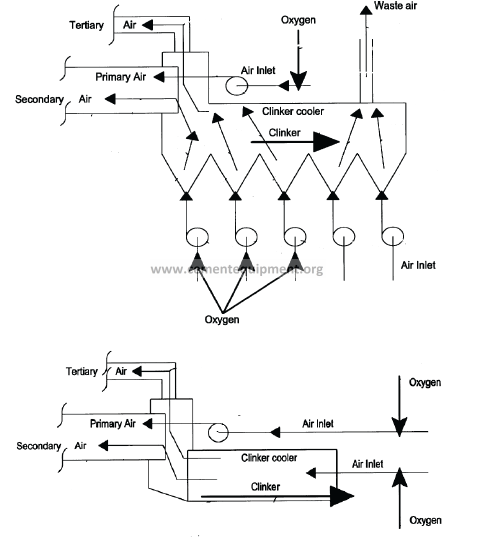
Introduction of oxygen in accordance with above allows a reduction in
flue gas volume (reduction in proportion of nitrogen in flue gas), as well
as increased heat transfer to the load and increase in production. The
addition of significant amount of oxygen to the air prior to the clinker
cooler increases the thermal efficiency of the cooler by additional
cooling of clinker and also increases secondary air temparature about
400 to 9000C. From figures oxygen is injected into the air before entering
the systems blowers . The oxygen enriched air can split between burner
oxidant inlet and the clinker cooler oxidant inlet. Oxidant enriched air
which is blown in clinker cooler. This pre heated oxidant-enriched air
then allowed or cause to flow into the kiln chamber and pre calciner as
secondary, pre heated, oxidant enriched air.
Introduction of oxygen prior to blowers increases the efficiency of the
plant by upto 10% when compared to introduction of oxygen through
conventional methods.
6.4 Installation of Latest generation High Efficiency Clinker Coolers:
The most common type of clinker cooler used in Indian cement industry
is the reciprocating grate cooler. Enthalpy from hot clinker is recovered
to preheat the incoming secondary and tertiary air for improving
thermal efficiency. Based on the cooling efficiency, technology adopted
and desired clinker temperature, the amount of air used in this cooling
process is approximately 2-3 kg/kg of clinker.
Conventional grate coolers provide recuperation efficiency of 50 to 65
%, depending on the mechanical condition and process operation of the
cooler, this corresponds to a total loss of about 120 -150 kCal/ kg clinker.
Several cement kilns in India, as a result of continuous productivity
increase measures, are operating at significantly higher capacities than
rated. This results in significant increase in cooler loading, ranging
between 50 to 70 TPD/m2 of cooler area in several cases; further
increasing the total heat loss from cooler.
Reciprocating cooler has undergone significant design developments
and several leading manufacturers offer latest generation clinker coolers
with significantly lower exit gas and clinker temperatures. As a direct
conseqiuence, Secondary and tertiary air temperatures offered by latest
generation coolers are in the range of 1250OC and 1000OC respectively
Retrofitting existing reciprocating coolers with latest generation coolers
offer significant potential for electrical and thermal energy saving in
Indian cement industry today. Total loss of latest generation coolers
stands at less than 100 kCal/ kg clinker and has recuperation efficiency
in excess of 75%.
Benefits:
Thermal Savings : 30 kCal / kg Clinker
Electrical Savings : 0.5 kWh / MT clinker
6.5 Replacement of Kiln inlet pneumatic seal with Graphite seal
Replacement of Kiln inlet pneumatic seal with Graphite seal gives the
following adavantages.
Advantages:
-Adjustable to any type and size of the Kiln
-Long lasting efficient leak tightness without any specific
maintenance
– Prevents false air into the kiln and ensures pressure stability in
kiln
– Prevents release of hot gases and dust from kiln
– Allows Increase in kiln throughput
– Lasts for 4-5 years
Principle:
– Circular bearing race is mounted on kiln and adjusted to
compensate any pre- existing eccentricity
-Graphite plates are mounted on a specific support which is bolted
on the fume box
-Graphite plates are held in contact with circular bearing with help
of 2 metal wires and adjustable counter weights
-Graphite plates overlap on each other to enhance overall leak
tight ness
Benefits:
Atleast 2-5 kCal/Kg clinker reduction in thermal energy possible
6.6 Impact of very low lime saturation factor11
The lime saturation factor (LSF) of Ordinary Portland Cement (OPC)
clinker typically ranges 88–95 in most of the Indian cement plants. In
order to achieve advantages in terms of higher compressive strength
particularly higher early strength, more and more C3S is being targeted
in the resultant clinker manufactured in Indian cement plants. In order
to achieve higher C3S in clinker, the lime content has to be increased
in the raw mix. Ideally speaking, LSF is desired in clinker such that the
actual lime present in the clinker is slightly more than sufficient to
combine with the theoretically calculated lime required to combine
with the other constituent oxides of clinker viz. silica, alumina and iron.
Due to heterogeneous nature of kiln feed, 100% lime combination is
difficult to achieve in industrially manufactured clinker. However, Indian
Cement plants are able to produce adequate quality of clinker keeping
LSF in the range of 88-95.
However, lowering of LSF is always beneficial in terms of conserving
good quality limestone as well as reducing GHG emission due to lower
limestone calcinations.Higher amounts of expensive and good quality
limestone are required to achieve higher LSF.
OPC clinker with lower LSF values are produced with low grade limestone
thus preserving fast depleting high quality limestone. Furthermore, raw
mix with lower LSF require lower burning temperatures and the same are
termed as soft burning mix which require reduced heat consumption.
The main disadvantage of OPC clinker with low LSF compared to OPC
clinker with higher LSF is the reduced content of Alite and relatively
increased content of belite and the consequential lower early strength
at an equal fineness level of cement. Such reduction in early strength
can however be made up to a limited extent by finer grinding of the
cement, which requires additional electrical energy and also affects
the output of the mill. Since the grindability of the clinker will depend
upon burning temperature and time, estimation of additional electrical
energy requirement is case specific. Clinker with lower LSF is found to
contain higher amount of belite which is relatively harder to grind than
alite thereby decreasing the Grindability index of the clinker.
Thermal savings: There will be reduction in thermal energy consumption
due to relatively lower LSF and thereby corresponding low CaCO3 content
of raw mix.
6.7 Improving the Burnability of Raw Mix by use of mineralizer12:
The potential use of mineralizers to improve the clinker quality and
facilitate energy conservation in cement manufacture is well-established
in view of the techno-economic aspects associated with them. There
are two overlapping terms namely, fluxes and mineralizers used in
cement manufacture. A ‘flux’ is an additive that decreases the melting
point of the liquid phase formed during clinkerization process, whereas
a ‘mineralizer’ is a substance that accelerates the reaction rates at all
stages or at some of the stages of clinkerization. In doing so, most of the
mineralizers act both as a flux; and as catalyst during clinkerization.
The possible reaction effects of mineralizers can be multifarious and the
important ones are summarised as follows:
-Accelerate the de-carbonation and sintering reactions
-lowering the clinkering temperature
– Broadening or narrowing the sintering temperature range
– Modification of liquid properties, such as viscosity, surface tension,
etc.
– Increasing the crystallization of the liquid phase
-Increasing clinker balling and ring formation tendency
-Promoting clinker-refractory interaction
– Altering the overall burnability and volatility conditions inside the
kiln
A large number of oxides are reported to act as mineralizers when added
as raw mix component during clinkerization. Some of the prominent
mineralizers are as under:
-Fluorides (viz., NaF, MgF2, CaF2, Na3AlF6, etc.)
-Fluorosilicates ( viz., Na2SiF6, MgSiF6, CaSiF6 etc.)
– Chlorides (viz., LiCl, CaCl2, MgCl2, ZnCl2, BaCl2, etc)
– Sulphates (viz., CaSO4, BaSO4, FeSO4, ZnSO4, Al2(SO4)3, etc.)
– Phosphates (viz., apatite, phosphorite, etc.)
-Carbonates (viz., K2CO3, MgCO3, BaCO3, etc.)
-Oxides, (viz., B2O3, Cr2O3, CuO, ZnO, MgO, MnO, TiO2, etc.)
-Industrial wastes, such as fly ash, non ferrous slags, etc.
Recent studies carried out have established that copper slag, a waste
generated during the extraction of copper metal in mineral processing
industry, has shown potential for use as mineralizer in cement
manufacture. Investigations carried out at NCB established its suitability
as a raw material (as a source of iron) in the manufacture of Ordinary
Portland Cement (OPC). Burnability studies at (1,300⁰C, 1,350⁰C, 1,400⁰C
and 1,450⁰C) of different raw mixes designed using conventional raw
materials along with varying doses of copper slag (1.5–2.5%) showed
mineralizing effect of copper slag. The clinkerization reaction was
found to be completed at 1400oC with improved microstructure in
the presence of copper slag as compared to control mix where phase
development was appropriate at comparatively higher temperature i.e.
1,4500C.
The mineralizers, in general, have been found to reduce the clinkerization
temperature by about 500C or even higher without compromising on
the quality of clinker. Such reduction in clinkering temperature has
direct bearing on reduction of fuel consumption, besides improvement
in clinker morphology. The selection and use of the mineralizers are
generally governed by the following considerations:
• Reaction effects desired;
• Compatibility with a given kiln feed;
• Process adopted;
• Physical form of mineralizers;
• Economic viability of using mineralizers.
Occasionally, to suit the requirement of a specific situation, combination
of mineralizers (viz., TiO2 + CaF2, FeSO4 + ZnSO4, CaSO4 + MgCO3 etc.)
are reportedly used. Under practical conditions of clinker burning,
both aspects of attainment of right temperature and the duration of
holding of material at this temperature govern the quality of clinker
manufactured and fuel consumption. Hence, the effects of mineralizers
can be viewed from their influence on:
-Temperature of initial liquid formation:
– Rate of formation of liquid during burning and duration of its
availability;
– Characteristics of the liquid such as viscosity, surface tension and
wetting and the influence of minor oxides such as alkalies, SO4
etc on these properties which in turn determine nodulisation and
solid liquid interface reactions;
-Chemical composition of liquid or liquids (in case of immiscibility)
and crystallization characteristics on cooling
Benefits
• Reduction in clinkering temperature by around 50OC
• Reduction in heat consumption by about 13 kCal / kg cl
• Reduction in power consumption up to 1 kWh / t cement
6.8 Utilization of Advanced Automation Systems in clinker
Manufacture:
Control and operation of kiln systems today are extremely complex,
properties of input fuel & feed materials diversely varying and product
standards becoming increasingly stringent. Cement kiln operators
today encounter such sudden variations and dynamic control of kilns
are therefore vital for achieving optimum results and lower costs of
manufacture.
Against this background, an effective advanced automation and control
system can bring in substantial improvement in overall performance
of the kiln, increased material throughput, better heat recovery and
reliable control of free lime content in clinker. Furthering the scope of
automation in process control, quality is also maintained by continuous
monitoring of the raw mix composition with the help of X-ray analyzer
and automatic proportioning of raw mix components. New type of online
bulk material analyzers have also been developed based on Prompt-
Gamma-ray Neutron Activation Analysis (PGNAA) for giving maximum
control over raw mix. The analyzer quickly and reliably analyses the
entire flow-on-line providing real time results. The latest trends in
on-line quality control include computers and industrial robots for
complete elemental analysis by X-ray fluorescence, on-line free lime
detection and particle size analysis by latest instrumental methods and
x-ray diffraction techniques respectively.
The latest trend in control systems is installation of Adaptive Predictive
control system. This Adaptive Predictive control system works based on
soft sensors input. This prediction mechanism works on set parameters.
The operation of system is predicted and corrective action is taken. If the
corrective mechanism is not as per the requirement (or set value), the
mechanism automatically refines itself. The system constantly upgrades
itself to meet the system fluctuations and keeps improving with time.
Benefits:
• Thermal savings : 6 – 8 kCal / kg clinker
6.9 Alternate Fuel Use in the Cement Manufacturing Process:
Cement industry is capable to co process wastes as alternative fuels
and raw materials to reinforce its competitiveness and at the same
time contribute to solutions to some of society’s waste problems in a
way which valorizes the waste and is beneficial to the environment.
Cement kiln have a number of characteristics which make them ideal
installations for disposal of industrial wastes through co processing route in an environmentally sound manner.
• High temperature (Flame temperature > 1800oC and material
temperature up to 1400oC)
• Long residence time
• Oxidizing atmosphere
• High thermal inertia
• Alkaline environment
• Ash retention in clinker
The use of waste as alternative fuels and raw materials in the cement
industry has numerous environmental benefits such as
1. Reduced use of mined natural materials such as limestone, bauxite,
iron ore etc and non-renewable fossil fuels such as coal. This also
reduces the environmental impacts associated with mining of these
natural materials.
2. Contributes towards a lowering of emissions such as greenhouse
gases by replacing use of fossil fuels with materials that would
otherwise have to be incinerated with responding emissions and
final residues.
3. Reduced requirement of land required for land fill option thereby
reducing the emission sand also liability associated with the
landfills.
4. Maximizes the recovery of resources present in the waste. All the
energy is used directly in the kiln for clinker production and the noncombustible
part of the waste becomes part of clinker.
Alternative fuel use in the Indian cement industry is presently at very
low levels; the country’s average stands at less than 1% of Thermal
Substitution Rate (TSR). Several nations globally have utilized cement
kilns as an effective option for their country’s industrial, municipal and
hazardous waste disposal.
The alternative fuels used in Indian cement industry at present
includes
1. Plastic waste
2. ETP sludge
3. Risk husk
4. Coal dust
5. Tire chips
6. Rubber dustroute in an environmentally sound manner.
Switching from conventional fuels to alternatives fuels at higher
substitution rates (>10 % of total thermal energy) may need additional
infrastructure like testing facilities for monitoring the quality of wastes
before usage, emission monitoring systems to achieve successful
utilization of such fuels . Some of the most commonly encountered issues
around utilization of alternative fuels are improper heat distribution
if residence time is low, increase in specific heat consumption due to
additional excess air, blockages in the preheater cyclones, unstable
operation, build-ups in the kiln riser ducts and higher SOx, NOx, and CO
emissions.
Latest dry process plants with state of the art technology however
has many controlling facilities and equipments like low NOx burners,
calciners with increased residence time, on line quality & emission
monitoring systems and latest fuel feeding systems having higher
accuracy & control that enables the cement plants worldwide to achieve
higher substitution rates.
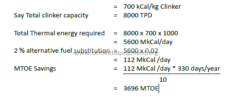
Efffect of AFR on Gate To Gate Specific Energy consumption as per BEE
PAT scheme:
As per the current version of BEE PAT scheme any alternate fuel used in
plant as a replacement of fossil fuel intake will not be considered as fuel
for gate to gate energy consumption leading to reduction in gate to gate
energy consumption.
The project implementation requires transportation system to carry the
waste fuel from storage bin to calciner
Say a plant with Average thermal SEC for baseline years 2007-08 to
2009-10
=
6.10 Rotor weigh feeder installation for Coal firing:
Rotor weigh feeder is highly accurate and reliable gravimetric feeding of
pulverised fuel.
Benefits:
1.Optimal flame Control:
The rotor weigh feeder actively compensates changes in material
characteristics and supplies a constant stream of coal to the
burning process. It supplies more accurate in deviation of set- and
actual feedrate. The stable feeding results out of the pro-active
control strategy and permanent gravimetric weighing and dosing.
2.Minimal Air Back-Flow from pneumatic transport system to
material storage silo:
The rotor is designed with many small chambers, each one
representing an air seal between the pneumatic transport and the
material storage silo
3.Long Service Life and High Availability:
This is achieved by a slow rotation speed of the rotor, only 6-8
rounds per minute. The only moving part, the rotor itself, is made
in a certain cast steel to minimise wear of both,sealing plates and
rotor.
4.Instantaneously Adjustable Feedrate
5.Eliminated CO-peaks
6.Reliable Feeding:
Optimised silo cones, material activators and calibration-hoppers
ensure reliable coal silo extraction. Accurate calculation of
pneumatic transport pipes ensure the transfer of the accurate
material stream from the rotor weighfeeder to the burner flame.
Installation of Rotoscale for Kiln coal and PC coal firing will result
in atleast 2 kCal/Kg clinker thermal energy.
6.11 Installation of Cross Belt Analyzers
Sampling of the material either the crushed lime stone or the raw meal
(input to the kiln) is done to maintain the stockpile quality and control
the chemistry of the raw mix thereby the chemical composition in the
clinker is maintained in proportion with the quality requirements. The
sampling of the raw materials helps in maintaining the homogeneity of
the raw mix such that the clinker quality is assured.
At present several plants are following conventional sampling and
quality control methods where the samplers installed does the sampling
for a few grams of material collected from large quantity of the material
collected at several intervals. These collected samples are getting
analyzed for its chemical composition through X-ray. Collection of the
samples and the analysis, results in time delay and manual error. This
results a lag time in doing the corrective measures for changing the
chemical composition and thereby affects the clinker quantity and the
energy consumption.
Whereas the cross belt analyzers, analyzes the chemical properties of
the materials and can take the corrective actions much quicker when
compared with the conventional sampling and quality control methods.
The cross belt analyzer in place of normal samplers has an added
advantage in terms of the quicker analysis results. These analyzers can
be installed either in the upstream of the stock pile and or before the
raw mill. The former option helps to track the cumulative chemistry
of the pile thus allowing the operator to direct haul trucks to different
sections of the quarry in a way that it will result in the final elemental
composition of the pile close to target. While the installation before the
raw mill can monitor the chemistry of the raw mix and automatically
trigger an adjustment in the proportions of the reclaimed stockpile and
take corrective actions in the varying the quantity of the additives.
The cross belt analyzers are needed in cases of heterogeneous deposits
of limestone is present or the limestone is received from more than one
mines. The advantage of cross belt analyzers in each stage is as below.
Upstream of Stock Pile
-Increase in mines life and conserves natural resource
-Reduces the raw material cost by minimizing the % addition of
other raw material additives
-Maintains the good limestone deposit for a longer time
Before Raw Mill
– Maintain lower standby deviation in kiln feed and thereby reduces
the specific energy consumption
-Stable kiln operation
-Consistent good clinker quality
-Reduces the cement grinding power
– Achieve higher blending levels of fly ash/slag in cement
– Maintain productivity levels in the kiln
Benefits:
Thermal savings : 3-5 kCal/Kg of clinker
6.12 Free Lime Control in Clinker Production with COSMA DP:
Freelime composition mostly used as indication for clinker burning.
Over burning of clinker leads to freelime in clinker lower than optimum
in most of the plants.
Overburning causes
1. Excessive fuel consumption
2. Reduced production
3. High NOx, short refractory life and harder to grind clinker
COSMA on-line analysis monitoring free lime and active clinker
minerals.
Benefits:
1. Reduced free lime excursions
2. Increase average free lime content
3. Reduce overburning of clinker
4. Reduction in fuel consumption
5. Reduction in NOx emission
6. Every 10° C reduction in kiln burn temperature saves 1% fuel
7. Fuel saved increases cement mill throughput
Ultimate performance of the finished cement is largely determined
in clinker production. COSMA online monitoring provides a real time
picture of the mineralogical changes as they are taking place. Thus
process engineers are able to construct control regimes that allow the
operators to maintain the kiln process at optimum performance levels
for both cost and quality.
6.13 Use Low Thermal Conductivity Refractory In Kiln inlet section
A modern cement kiln at present operates with 6 stage pre heater suitable
precalciner system with tertiary air ducts and highly efficient burning and
cooling Each plant is committed to become the most competitive and
profitable one through increasing the clinker production at the reduced
or optimum cost. In order to keep pace with the present scenario where
the cement industry is progressing and modernizing fast it is essential
to ensure maximum kiln availability and therefore optimum refractory
lining scheme and its performance in a cement rotary kiln system For
inspection and monitoring to identify areas of potential.
In general practice in the kiln 40% Alumina brick lining will provided
from Kiln inlet about 20 m range. Thermal conductivity of this brick is
1.4 W/m.K (at 12000C hot surface temperature). Resulting in Kiln surface
temperature will vary from 2500C to 3200C in this area.
Because of high surface temperatures, The heat loss through the surface
is high. The radiation loss from Kilns will be 25- 35 KCal/Kg clinker, which
is in higher side.
Thermal energy savings are possible by replacing these bricks with low
thermal conductivity Bricks. Replacing the 40% Alumina bricks with low
thermal conductivity refractory of thermal conductivity 0.6 W/m.K.
helps to maintain Kiln shell temperature less than 2500C in the Kiln inlet
area.
Benefits:
Thermal savings : 2-3 kCal/Kg of clinker
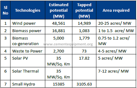
6.14 UTILIZATION OF RENEWABLE ENERGY
Any renewable energy project implemented within the boundary of
plant for replacement of power input to the plant will not be considered
as energy for gate to gate energy consumption.
Renewable energy is a cleaner and greener way to generate power.
A modern 1 million capacity plant today requires a total energy
consumption of 10 MW. It can be very attractive to go for 100%
renewable power generation by design.
Few of the renewable energy technology, their estimated potential and
the area required to generate power is as mentioned below
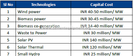
The Cost estimation of various different renewable energy projects is
been mentioned below :
Section 3
WHR & CPP
CHAPTER 7
WASTE HEAT RECOVERY
7.1 Introduction:
In Cement plants significant amount of heat is carried by pre-heater
exhaust gas and cooler exit air. Depending on the number of stages
in the pre-heater and the type and technology adopted in the cooler
section the temperature in these gas streams vary from 200 0C to 360 0C
/400 0C.
If the moisture content in the raw material such as limestone, fly ash is
high this heat is utilized effectively to remove the moisture present in
these materials. Otherwise it is rejected to the atmosphere and hence
potential exists to recover the same.
Three types of technological options are available in the market for
waste heat recovery such as
-Rankine Cycle
-Ogranic Rankine Cycle
-Kalina Cycle
Both the Rankine cycle and Organic Rankine cycle plants are being
operated in India as well as in abroad for the waste heat recovery.
The Kalina cycle which is more efficient of all the three, is under
implementation (2012) in cement industry.
Despite high investment costs the following other problems have to be
considered while going for WHR systems:
-Loading of the power plant
– Additional power consumption in preheater fan, cooler vent fan
-Dust load in the gas stream
-Water availability (if conventional Rankine cycle is considered)
Power generation from waste heat has the following advantages:
-Lower generation cost
-Green house gas reduction
-As a part of Corporate Responsibility for Environment protection
-Better corporate image
-Lower operating / Energy cost
-PAT benefits
Many of the cement plants in India / world have taken up this initiative
by incorporating CDM route to meet the high initial investment.
%Heat Recovery and temperature profile of different types of Waste
heat recovery systems
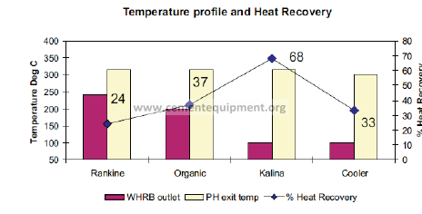
The graph shows the recovery of heat from various technologies for
the same preheater outlet temperature of 316 Deg C (5 stages). Cooler
exit gas is considered as the preheating source in combination with the
preheater waste heat recovery boiler and hence 33 % heat recovery is
considered for cooler air for all the systems.
Most the clinker manufacturing units in India have 2 and more kilns in
the same location or site to meet the clinker demand. It may be noted
that though the heat availability in individual kiln / cooler may be less,
the total heat availability in the locating including all the kilns may work
out a sizable quantity to work out waste heat recovery potential.
7.2 Influence of dust in waste heat recovery:
-Presence of dust will affect the heat transfer rate by forming
coating over the heat transfer areas in the Waste Heat recovery .Boiler which in turn will affect the efficiency of the cycle.
-Presence of dust can result in abrasion there by failure of tubes /
heat transfer equipment
-Dust may form coating / blockage
Problem of dust can be handled by
– Improving the efficiency of the top stage cyclone in the case of
Preheater.
-Reducing the aeration velocity at the top of clinker bed in the case
of cooler by increasing the grate area or maintaining optimum
cooler loading.
– Installing pre expansion chambers which will help to remove the
bigger size particles
– Improving the distribution of the gas inside the Waste Heat
Recovery Boiler (WHRB) to maintain uniform dust concentration
and gas velocity and to avoid excessive wear in any particular
location due to turbulence
– Carefully designing the WHRB such that the gas velocity is within
acceptable range.
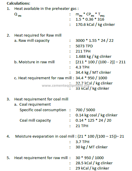
7.3 Estimation Of Waste Heat Recovery Potential
Basic data & Assumptions:
1. Kiln capacity : 3000 tonnes per day
2. No of stages in the preheater : 5
3. Preheater exit gas details
a. Volume (mPH ) : 1.5 Nm3/ kg clinker
b. Specific heat capacity (CPPH ) : 0.36 kCal / kg / 0C
c. Temperature TPH1: 3160C
4. Cooler exit gas details
a. Volume (mC ) : 1.0 Nm3 /kg clinker
b. Specific heat capacity CPC : 0.317 kCal / kg / 0C
c. Temperature TC : 3000C
5. Limestone moisture content LM : 2 %
6. Raw mill running hrs : 22 hrs / day
7. Kiln running days per annum : 335 days
8. Heat transfer efficiency of WHR boiler – EFFWHR : 75 %
9. Heat transfer efficiency of AQC boiler – EFFAQC : 75 %
10. TG system efficiency EFF TG : 33 %
11. Specific heat consumption : 700 kCal / kg clinker
12. Raw coal moisture : 15 %
13. Raw meal to clinker factor : 1.55
14. Heat requirement for moisture in raw mill & Coal mill: 950 kCal /
kgwater
15. Calorific value of fine coal used: 5000 kCal / kg coal
16. Coal mill running hrs per day : 20
17. PH gas temperature at WHRB outlet TPH2 : 240 0C
18. Cooler exit temperature at AQC boiler outlet TC2 : 120 0C
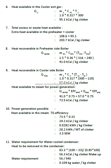
Excess heat available in the preheater:
Heat available in the PH gas minus heat required for Coal mill & raw
mill
Excess heat available (preheater) : 170.6 – (29 + 33)
: 108.6 kCal / kg clinker
7.4 PAT Benefits:
Chapter 8
Heat Rate Reduction Opportunities
in Captive Power Plant
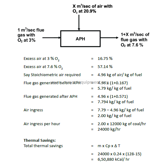
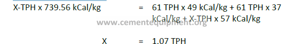
8.1 Arrest Air Ingress In Flue Gas Path Of Boiler
The performance of the APH can be analyzed based on the O2 level in
the flue gas at various points such as before air preheater, and after APH
have been measured.
During analysis in a plant measured Oxygen concentrations given
below.

There is a continuous increase in O2 level along the flue gas path.
Significant increase in O2 level is observed after APH. This clearly
indicates that there is air leakage into the system. The leakage estimation
calculations are given in the backup calculations.
The quantity of air leakage into the flue gas path is about-31.12 %.
This air leakage into the flue gas path leads to further reduction in flue
gas temperature. The reduction flue gas temperature further increases
the low temperature end corrosion and further increases the leakage
level. The air infiltration also leads to increased load on the ID fan and
hence increases ID fan power consumption.
There is a good potential to save energy by arresting the air leakage
in the APH. This will also results in marginal reduction in ID fan power
consumption.
Periodically monitor the O2 level in the locations like before the air
preheater, after the air preheater and after the ESP. Reduce the quantity
of air infiltration in the ESP by improving the sealing. Cover the expansion
joints with materials like thermofabric etc. Check for leakages in APH
tubes.
8.2 Reduce Steam Consumption In Steam Ejector In TG
In a plant the following observations made during the study of the
performance of the vacuum system are given below.
-Steam jet ejectors are in operation for creating vacuum. Presently
steam at a pressure of 10.00 kg/cm2 is utilised as motive steam.
This steam pressure is achieved by reducing the main steam from
64 kg/cm2 to 10.00 kg/cm2.
-The steam consumption is estimated indirectly by measuring the
quantity of water flow and the temperature difference across
the ejector condenser. The detailed calculations are given in the
backup sheet.
-The steam ejectors are designed for steam consumption of 0.67
TPH at 10 kg/cm2. The estimated steam consumption for the
ejector is:
♦♦ TG : 1.00 TPH
-When compared to design, about 0.33 TPH of steam is consumed
more in the ejector of TG. This extra steam consumption can be
saved by addressing the problems of ejector.
The steam flow through the ejector is estimated indirectly by measuring
the water flow through the condenser and the temperature difference
across the condenser.
Heat and Mass Balance:
The steam consumption for TG steam ejector = 1.00 TPH
Design consumption of steam ejector = 0.67 TPH
Difference in steam consumption = 0.33 TPH
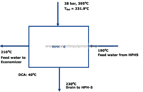
8.3 Improve The Heat Rate Of Steam Turbine
In a plant the performances of all heaters studied. There are two HP
heaters, one Deaerator feedwater heater and four LP heaters to heat the
boiler feed water at various stages. The order of heating is as follows:
Condenser gLPH-1gLPH-2gLPH-3gLPH-4gDEAgHPH-5 g
HPH-6gECOgBoiler
– The heat rate estimation of steam turbine in was done based on
the actual measurements, online parameters and estimation.
-The design and operating parameters of steam turbine at various
stages are given below:
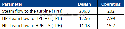
-The steam temperature at the discharge of HPH – 6 is maintained
below the Designed Economiser inlet temperature. Steam
consumption is less for HPH – 6 when compared to that of the
design.
The design work output, heat (( rate and overall system efficiency of
the steam turbine is
♦♦ Turbine = 55.01 MW
♦♦ Heat rate = 2299.69 kCal/kWh
♦♦ Overall Turbine efficiency = 37.40%
-The operating work output, heat rate and overall system efficiency
of the steam turbine is
♦♦ Turbine = 49.63 MW
♦♦ Heat rate is = 2618 kCal/kWh
♦♦ Overall Turbine efficiency = 32.84%
– There is a significant deviation between the design and operating
condition of the steam turbine.
-Possible reasons for increase in heat rate:
♦♦ Poor Performance of HP heaters
♦♦ Improper distribution of steam
♦♦ Passing of valves mainly at distribution junctions and drain
valves
♦♦ Heat loss across the pipe lines
– The performance of HP heaters analysed to estimate the reasons
for higher heat rate. Two basic parameters are required for any
type heaters to analyse the performance. They are:
♦♦ Drain Cooler Approach (DCA): It is defined as the difference
between steam drain temperature and inlet feed water
temperature.
♦♦ Terminal Temperature Difference (TTD): It is defined as the
difference between saturation temperature of inlet main
steam and the outlet feed water temperature.
-The design and operating parameters of DCA & TTD of all the
heaters are given below:
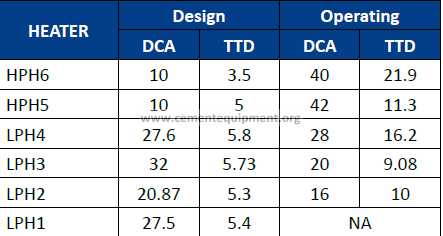
– The DCA and TTD of the heaters HPH 5 & 6 indicate that the
performances of these heaters are affected badly.
-When compared to design, the DCA & TTD of HP heater–6 and
HP heater–5 are higher. It is learnt that, the bypass valve of HP
heater-6 was kept intentionally open because of mismatch
between the designed heater outlet temperature and designed
boiler economiser inlet temperature.
♦♦ By doing so, the feed water temperature achieved at the
outlet of HP heater-6 is only 2100C against the design value
of 232.70C.
-By increasing the feed water temperature at the HP heater-6
outlet, the flue gas temperature at the boiler outlet may increase,
if we cannot utilize the heat effectively in Air-preheater.
♦♦ By raising the feed water temperature at HPH-6 outlet, it
is estimated that the performance of heater will improve
and the performance of the boiler deteriorates. It is also
calculated that gain on heater performance is more beneficial
than losing on boiler efficiency.
-There is a good potential to improve the performance of heater
as well as heat rate by avoiding the HP heater-6 bypass valve
operation.
To improve the heat rate of turbine:
-Avoid bypassing HP heater-6. This can increase the feed water
temperature up to the designed value at HP heater outlet there by
improving its performance.
-Periodically check the performance of HP and LP heaters in all the
units by monitoring the following parameters of the heaters:
♦♦ Drain cooler approach
♦♦ Terminal temperature difference
– Any deviation of the above parameters from the design value is
a clear indication of deterioration in performance the heaters.
In such a case, adjust the level of heaters and accordingly try to
maintain the designed TTD and DCA.
-Check the status of drain valves, drag valves and control valves to
eliminate the possibility of passing.
The schematic diagram for the HP heater is shown below:
Benefits
Heat rate reduction – 60 kCal/kWh can be saved.
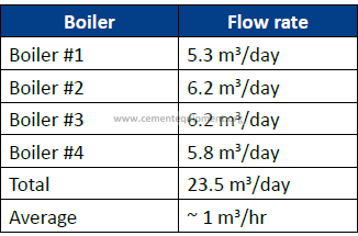
8.4 Recover Flash Steam from Boiler Blow Down
In a plant steam saving opportunities were explored in boiler system.
-Four boilers are in operation in the plant. Which generate steam at
a pressure of 95 kg/cm2.
-TDS level in the boiler is monitored based on silica content at less
0.2 ppm.
-In the four boilers installed, continuous blow down is practiced.
The rate of blowdown is maintained steady and fine tuned based
on the silica content of the blow down.
– At present a boiler blow down vessel is installed and the flashes
from the blow down are being vented out in atmosphere and the
remaining liquid drained. The quantities of this drain from different
boilers are given below.
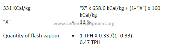
– There is a good potential to recover flash steam from boiler blow
down by putting flash vessel. The flash steam from the CBD vessel
can be utilized in the deareator.
This will result in reduction in
steam consumption in the deareator by about 0.47 TPH.
Blow down water quantity measured = 1 TPH
Enthalpy Balance was carried out to estimate available flash steam
8.5. Energy Saving Opportunities in Diesel/HFO Genset based
Captive Power Plant:
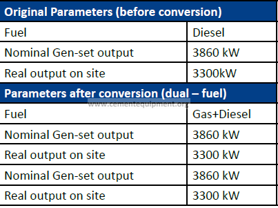
8.5.1 Partial Gas Conversion to reduce Fuel Oil Consumption:
Bi Fuel Conversion :
Conversion of Diesel Engines to Bi Fuel (two fuels at the same time Diesel/
HFO and Gas)
BI-Fuel (Dual Fuel) Conversion of Diesel & HFO generating sets:
With Bi-fuel conversion of the standard diesel engine the actual dieseling
process must be always maintained. No Bi-fuel kit can replace 100% of the
engines diesel use with available gas.
The natural gas will be introduced to the engine cylinders for the Bi-fuel
conversion and used as the substitute fuel for the generation of cylinder
power.
With the ComAp solution following parameters are controlled/monitored
automatically:
1) The diesel portion
2) The Engine exhaust temperatures
3) The boost air temperatures
3) Knocking (via frequency based pre-detonation control system)
4) The actual load and electrical tolerances
Bi-fuel conversion requires virtually no engine modification and brings
double benefits in every application:
– Affordable diesel engines combined with inexpensive natural gas
– Economic solution for slow-speed, middle-speed and high-speed
engines
– Flexible use of fuel
-Guaranteed power output
– Efficient and safe operation with lower emissions
– Longer engine life and reduced maintenance costs makes it less
payback period.
Norms of Specific Fuel Consumption for Diesel/HFO Gensets:
Diesel Engines – High Speed : 260 to 275 ml per Kwh
Diesel Engines – Slow Speed : 245 to 265 ml per Kwh
Density : 0.83 Kg per Litre
HFO Engines – Slow Speed : 190 to 210 ml per Kwh
Density : 0.96 Kg per Litre
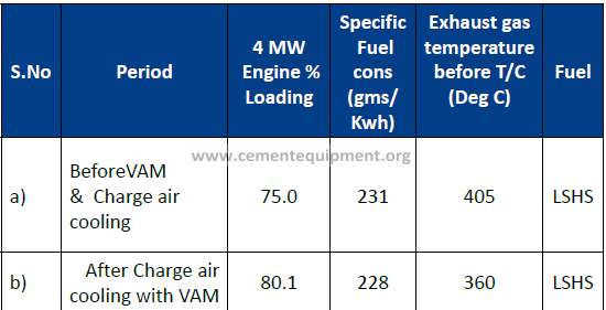
8.5.2 Charge Air Cooling:
Effect of Charge air temp on Fuel Consumption & Loading:
Fuel Consumption : 1.5 gms/Kwh for every 100C temp rise
Engine Loading Reduction : 5 %
Check the following parameters for Engine loading is limitation
-High HT Water Temperature
-High Charge Air Temperature
-High Exhaust Gas Tempemperature
4 MW Engine Block Cooling Jacket Hot water based Chiller Capacity : 130 TR
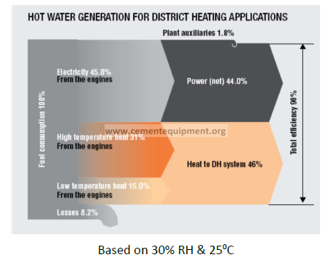
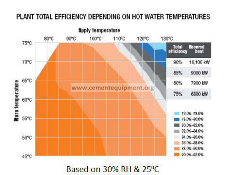
8.5.3 Combined Heat and Power Generation:
Hot water generation from engine waste heat and use the hot water for
absorption chiller to use in air conditioning application / cold storage.
8.5.4 Know the Fuel Oil Quality and its effects on Engine:
High dirt matter: Increased wear and tear and increase in specific fuel
consumption.
High viscosity : Poor atomization and increase in specific fuel consumption
High Sulphur : Increased wear and tear and increase in specific fuel
consumption / SOx Pollution
High Carbon Residue: Increased soot formation and increase in fuel
consumption / smoke emission.
Section 4
Latest Developments
9.1 FL Smidth In-Line Calciner (ILC) for NOx reduction
In-Line Calciners:
In-Line calciners are generally known
to generate lower NOx emissions
than Separate-Line calciners since all
of the kiln exhaust gases must pass
through the calciner.
100% of the fuel is fired to the kiln
riser duct. As a result, it is possible to
obtain both reducing conditions and
high temperature zone in one simple
system (without multiple firing
points) for the lowest possible NOx
emissions.
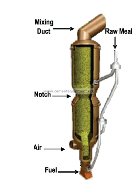
The fuel is injected into the kiln riser
below where the tertiary air enters
at the base of the calciner. This socalled
reduction zone, sized for a particular gas retention time, has an
oxygen deficient atmosphere that promotes NOx reduction.
The optimum temperature in the zone is controlled by a material split
from the second lowest stage between the calciner and the kiln riser.
This material split is also used to control possible build-up within the
kiln riser. Above the reduction zone is the main calciner vessel, which is
divided into two or more sections separated by a notch.
The changes in cross-sectional areas create turbulence that ensures
effective mixing of fuel, raw meal and gas, improving heat transfer and
combustion.
The calciner outlet loop duct ensures optimum gas retention time,
further mixing and complete fuel combustion. Optionally, the secondor
third-lowest stage cyclone material can be further split to allow for diversion of a portion of the meal directly into the upper section of the
calciner. This creates a “hot zone” in the lower section of the calciner
that is conducive to burning difficult fuels and further NOx reduction.
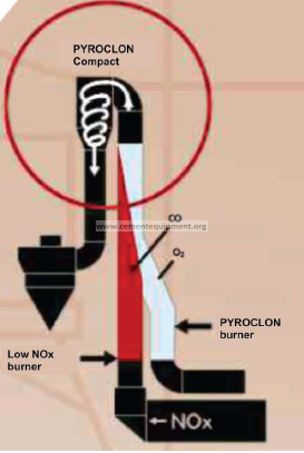
9.2 KHD Humboldt Wedag PYROCLON Calciner:
The standard calciner for oil
and gas is the PYROCLON®- R
with PYROTOP® compact swirl
chamber. The PYROCLON®- R
LowNOx with PYROTOP® is the
standard calciner for using
solid fuels.
Both calciners have proved their
capabilities of reaching emission
limits of worldwide legislation
without the use of additives.
The reduction of NOx emissions
in the LowNOx calciner is based
on the principle of “continuous
staged combustion”. Meal and fuel are fed into
both parallel gas flows. In the
LowNOx zone, a portion of the
fuel is burned with the kiln gases generating a reducing atmosphere
zone which lowers the NOx content of the kiln waste gases.
The reducing gas strand from the LowNOx zone is united with the
oxidizing gas strand and later intensely mixed in the PYROTOP® compact
swirl chamber. Due to this turbulent mixing, the remaining CO oxidizes
to CO2 with the oxygen present in the gas stream.
To achieve a highly efficient thermal utilization for less ignitable fuels,
e.g. petcoke or anthracite, the calciner can be easily extended to increase
the retention time to more than five seconds.
Depending on the physical and chemical properties of the secondary
fuels, up to 100 percent of the fuel required in the calciner can be
substituted
The reducing gas strand from the Low NOx zone is united with the
oxidizing gas strand and later intensely mixed in the PYROTOP® compact
swirl chamber. Due to this turbulent mixing, the remaining CO oxidizes to CO2 with the oxygen present in the gas stream. The use of lumpy
secondary fuel or fuels characterized by poor ignitability becomes
possible by additional installation of a combustion chamber equipped
with a “hot spot” burner. Depending on the physical and chemical
properties of the secondary fuels, up to 100 percent of the fuel required
in the calciner can be substituted.
Advantages:
– Even distribution of raw meal, fuel and combustion air across
-the entire section
-Complete fuel burnout
-Optimum heat transfer between fuel and raw meal
– High calcination rate up to 95 percent.
– staged combustion
– Emission level: < 500 mg NO2/Nm3 with gas,oil, lignite and most
kind of coals
9.3 Latest Generation Coolers:
9.3.1 Cladius peter η-Cooler:
Static inlet:
The HE-Module opens up from the kiln drop point to the transport lanes
by means of refractory concrete. Here an optimal clinker distribution
over the width is achieved. With the HE module, which consists of a
static inclined grate, the risk of snowmen forming is virtually eliminated,
while also ensuring a protective clinker layer on the module itself. The
HE module is aerated via independent zones, each zone has it’s own flap
to adjust the air volume. Due to the flexibility of the air distribution, it is
possible to control the kiln discharge conditions even with the changing
environment, due to the use of different fuels and raw materials
fluctuations.
Transport System:
The η-Cooler uses a transport system that is unique to any of the present
coolers. The transport is based on the well proven ‘moving floor’ system
that has long been in operation for materials handling. The η-Cooler
consists of parallel transport lanes which are moved together in the
direction of the clinker transport (forward stroke) and individually or
alternatively in groups retracted (backward stroke).
Depending on the required throughput capacity, a corresponding
number of parallel transport lanes is installed, each supported on
independent rollers.
Due to Independent Lane Movement (ILM) (parallel, individually driven
aerated lanes), the flow behaviour and material speed at the sides can
be actively influenced. The slots for the air supply are integrated in
the transport lanes by utilizing the Mulden grate plate principle Each
transport lane is sealed by means of a labyrinth, which eliminates the
need for a dust removal system. This together with the fact that the
transport lane system is typically offered without any inclination makes
the η-Cooler design extremely compact.
Aeration Concept:
Since no installations are required inside the clinker layer the entire
cooler bottom is fully aerated leading to uniform cooling and optimum
recuperation. Additionally the η-Cooler still makes use of the chamber
aeration principle – a well-proven aeration concept in conventional
grate cooler design. However, in contrast to reciprocating grate coolers
the η-Cooler allows for a longitudinal division into chambers. This gives
the advantage of chamber side aeration (CSA), which improves cooling
at the critical side areas of the cooler. With Chamber Side Aeration (CSA)
and Independent Lane Movement (ILM) Claudius Peters can, as no other
cooler supplier, actively influence the two most important parameters
in clinker cooling. This gives us the possibility to virtually eliminate such
problems as red river.
Features:
– Extremely compact design
-No dust removal system required
-Complete autogenous wear protection
– Long strokes = low grate speed
– Variable stroke length over the cooler width
– No conveying parts within the clinker bed
– less wear significantly reducing maintenance
– no obstructions to the clinker flow
– constant transport efficiency over cooler life
– Controlled air distribution – chamber side aeration
Benefits:
– Low construction height
– Modular design – quick to install
– Optimum cooling and heat recovery
– Optimal distribution of clinker across cooler width
-Lower operating costs
-High reliability
9.3.2 FLS – SF Cross bar cooler:
Advantages:
-High thermal efficiency
– High secondary and tertiary air temperature
-Stationary air distribution plates
– Clinker conveying and air distribution systems are separated
– No sealing air
– Air distribution plates with mechanical flow regulators (MFR)
– Reduced electrical power consumption
– No thermal expansion of grate line
– Long service life of air distribution plates
– No fall-through of clinker
– No undergrate clinker conveying system
– Easy operation
– Easy maintenance
– Easy installation & Modular design
Innovative features: Cross-bars, separate clinker conveying device
The SF Cross-Bar Cooler has no movable grate plates. There is no
fall-through of clinker and no undergrate clinker conveying system is
required. A static layer of clinker protects the air distribution plates
against heat and wear, so the plates will remain in service for a long
time. Reciprocating crossbars fitted above the stationary air distribution
system effectively convey, mix and shear the clinker while at the same
time preparing the clinker for efficient exposure to the cooling air.
The cross-bars work according to the same principle as reciprocating
cooler grates, but gradual wear of the cross-bars has no effect on cooler
operation and thermal efficiency, as the conveying and air distribution
systems are separate.
The cross-bars are held in position by retainer brackets. All wear parts
are easy to install and replace.
Mechanical flow regulators and air distribution plates
Mechanical flow regulator In the SF Cross-Bar Cooler each air
distribution plate is equipped with a Mechanical Flow Regulator (MFR)
which regulates the airflow to each plate via a self-adjusting orifice. The
MFR maintains a constant airflow through the air distribution plate and
clinker bed, irrespective of clinker bed height, particle size distribution,
temperature, etc.
If for some reason the restriction of airflow through the clinker layer
changes locally, the MFR automatically compensates for the variations
in restriction and maintains the desired airflow.
The MFR working principle is entirely based on simple physical laws
without any electrical controls. The MFR prevents the cooling air
from taking the “path of least restriction”. This helps to optimise heat
recuperation and distribution of air throughout the entire grate cooler,
which in turn allows fuel savings and/or an increase in throughput.
Air distribution plate
The air distribution plates of the SF Cross- Bar Cooler are characterised by low pressure drop. The MFR system adds little to the pressure drop
during normal operation, due to the large orifice area. So the undergrate
pressure is considerably lower than in traditional coolers, which in turn
saves electrical energy.
Air is supplied from one fan to each undergrate compartment, established
when fitting the modules side by side together. The SF Cross-Bar Cooler
has no internal ducting within the undergrate compartments.
The protective layer of static clinker between the cross-bars and the air
distribution plates prevents wear of the air distribution plates.
Modular concept
The entire SF Cross-Bar Cooler is constructed as a modular system
with a fixed inlet module followed by standard modules (1.3 m wide
x 4.2 m long or 4 x 14 air distribution plates). The standard modules
are preassembled in the workshop to ensure high quality and swift and
easy installation. Each module includes a movable frame activated by
a hydraulic cylinder. The movable frame is guided by four linear guide
bearings and has two drive plates.
The drive plate penetrates the grate line via two slots, which extend
throughout the entire module length. On top of the drive plates a
patented sealing profile forms a dust trap, preventing clinker from
entering the undergrate compartment and, consequently, eliminating
the need for a dust spillage conveyor. The sealing profiles extend
throughout the entire cooler length, which means that during the
reciprocating movement of the profiles, the ends are never exposed to
wear by the clinker.
Because the standard modules consist of standard mechanical
components, very attractive equipment delivery times can be offered.
The modular cooler concept allows different configuration patterns for
various cooler sizes, depending on production level, clinker temperature
requirements, etc.
Process improvements
The SF Cross-Bar clinker cooler concept features improved thermal
efficiency, resulting in high secondary and tertiary air temperature,
which lowers overall heat consumption. High thermal efficiency and
reduced power consumption are maintained throughout the life of the
cooler, irrespective of the wear on the conveying system.
This is due to the:
-impact zone with stationary inlet module
-compartment aeration without inefficient sealing air
-optimised air distribution throughout the service life of the cooler,
ensured by the mechanical flow regulators reduced amount of
cooling air and consequently
– lower air quantity for dedusting
– reduced number of cooling air fans
– separated mechanisms for conveying of clinker and cooling of
clinker
Easy maintenance
The number of wear parts has been minimized through the simple
design of:
-Cross-bars
– Retainer brackets
– Sealing profiles.
Moreover, these parts are designed to last two “campaigns” or more.
Grate plates are no longer considered wear parts. All wear parts in the
cooler are easily replaced in less than four days.
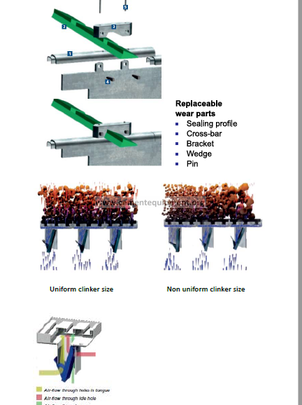
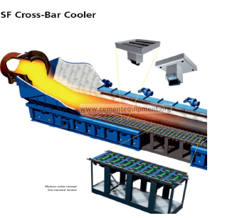
9.3.3 Humboldt Wedag grate coolers:
Advantages:
– Optimized heat transfer ensuring high thermal efficiency
-Reduced heat consumption for the kiln process
-High clinker quality due to rapid cooling
-Excellent control of cooled clinker temperature
-Less cooler vent air for greater ecological acceptability
– Suitable for all kiln processes
– Considerably reduced grate riddlings
– Higher specific grate loading
– Automatic operation
– High operational reliability due to the robust design
– Less maintenance
HUMBOLDT WEDAG grate coolers with capacities over 5000 t/d have
been installed throughout the world. Experience gained with more
than 400 rotary kiln cement plants has led to the development of the
third generation of HUMBOLDT WEDAG grate coolers, The recuperation
efficiency of a PYROSTEP® grate cooler is between 70 and 76 %,
depending on the type of kiln systern.
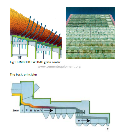
Zone I:
comprises a stationary step grate with horizontal air outlets in the
plates. The individual rows are aerated in several transverse sections
with a pulsating and individually adjustable stream of air. This design
ensures that the clinker is uniformly distributed over the full width of
the cooler.
The classical “horse-shoe” coverage of individual plates is reduced or
disappears entirely and the creation of a “red river” is eliminated by
directing the air flow to specific areas in the clinker bed.
The thermal and mechanical stresses imposed on the step grates are
minimized by the constant presence of a layer of cold clinker.
Zone II
This is a reciprocating grate section equipped with newly developed
omega plates for aeration in rows. These plates have small pockets in
which the clinker accumulates, thus ensuring a widespread and uniform
flow of air through the layer of clinker.
The lip of the omega plate is also cooled with air to extend the service
life. A wearresistant external telescopic seal makes it possible to supply
cooling air to the moving rows via rigid pipes, thus making hoses and
flexible connections unnecessary. In the case of small cooler units, zone
II is followed directly by zone V with chamber aeration.
Zone III
comprises a stationary step grate similar to zone 1. This ensures that
the advantages of a step grate can be fully utilized, even at high clinker
throughput rates, without the risk of clinker flushes.
Zone IV
This is also equipped with omega plates (similar to zone II). The length
of this one depends on the process requirements and the capacity of
the pyro process System.
Zone V
This is aerated by chambers and can be equipped with standard or omega
plates. The specific cooling air distributed to each plate is calculated to
ensure the prevention of inrushes of air causing clinker to whirl up in
fountains. The clinker is consequently cooled very uniformly. The gaps
between the plates have been narrowed to reduce clinker trickling.
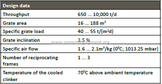
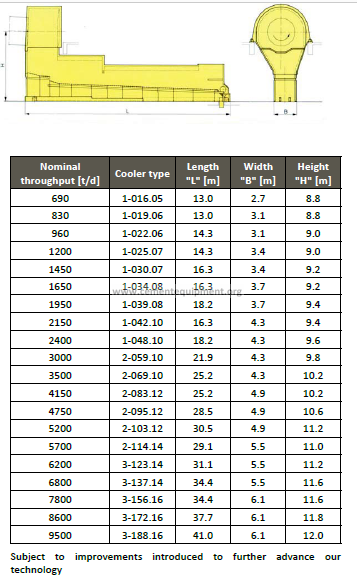
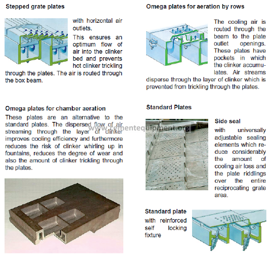
9.3.4 IKN Pendulum Cooler
Features and general process description
– Horizontal aeration (COANDA effect)
– Fixed clinker inlet distribution system (KIDS)
– Slow grate speed and reduced number of mobile rows
-Hydraulic drive with single or double cylinder located outside the
cooler housing
-Low specific electrical energy consumption
– Constant thrust gaps and maintenance free grate suspension due to
IKN Linear Pendulum Support (LPS)
– Cooler capacity of up to 13.000tpd in operation as of 2012
The sintered clinker leaves the outlet of the kiln with an estimated temperature
of 1400°C and drops onto the static inlet (clinker inlet distribution system),
referred to as KIDS (Fig.1), where the clinker is initially cooled and conditioned
for uniform distribution to the pendulum-supported grate (Fig.2). The clinker
is transported by linear strokes of the pendulum section, every third row
being movable. The clinker bed, 550-650mm deep, travels past the middle air
offtake which is located separately behind the kiln hood. Typically middle air
is utilized for waste heat recovery systems or for drying purpose
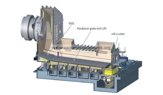
After travelling the total grate length the clinker temperature will have been
reduced to a theoretical value of about 65°C plus the ambient temperature
when it falls onto the roller crusher. The crusher has three to six rollers with
maximum width of 4.8m.
Each crusher roll is driven by an electric motor with bevel planetary gear.
After crushing the clinker maximum grain size is 25 x35mm and it leaves the
cooler via a chute which discharges the clinker onto the clinker conveyor for
transport to the clinker silo.
Fig. 2: IKN cooler including KIDS
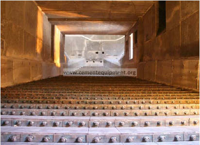
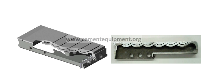
Fig. 3a/b: IKN grate plate with Coanda-Nozzles
The Coanda Nozzles of the pendulum section are formed by several blades
which are inserted into a common supporting frame. The curved air
openings between the blades generate the desired horizontal Coanda jets
(Fig.4).
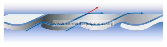
Fig. 4: Coanda-effect
The surface of the frame is completely covered by the blades to form a grate
surface which is no longer composed of entire grate plates. The supporting
frame is not subject to wear.The blades are loosely interlocked into a base
frame and are free of mechanical and thermal stress. This is crucial as it
allows the material composition to be optimized for wear resistance only.
The blades are made as hard as the clinker, significantly increasing the
service life of the grate surface. While each cooler has thousands of such
blades, only single blade replacements have been reported.
Clinker Inlet Distribution System (KIDS)
The IKN KlDS (Fig.5) distributes the clinker evenly across the grate width and
conditions the clinker bed to improve its air permeability. The inclined slots
of the Coanda Nozzles generate horizontal air jets which pressurize the
bottom layer of theclinker bed. The air jets become vertical upon striking
against clinker particles and uniformly penetrate the clinker bed. Fines are
sifted out of the voids between larger particles and accumulate at the
surface where they fluidize.The bed voidage in each layer within the clinker
bed is maximized. The main features of the IKN KIDS are:
-Uniform clinker distribution across the grate width
-Transport of the fines to the bed surface
-Rapid cooling of the lower clinker bed
-Lower clinker outlet temperature
-Less maintenance of the grate
– Improved recuperation
– Power savings due to reduction of cooling air and pressure
– Stabilized kiln/cooler operation
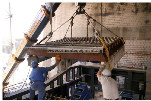
Fig. 5: KIDS erection
KIDS, stands for a revolutionary success in clinker cooling – in mechanical
and process terms. Typical improvements are measured as heat savings of
20 to 100 kCal/kg depending on the base line. IKN guarantees savings in
terms of cooler losses which result in a reduction of kiln fuel consumption.
Linear Pendulum Support
The high degree of precision in design and fabrication achieved with the
blade technology called for a dedicated gap management between movable
and stationary rows. This requirement was solved by the LPS support of the
movable structure. LPS is short for Linear Pendulum Support (Fig.6), IKN’s
patented support, guaranteeing a linear movement, which provides a
constant gap width at all times. The LPS is the advancement of IKN’s
pendulum strap suspension, which proved successful for almost two
decades. It is a combination of wearless and maintenance free suspension
blades making up a compact unit with dimensions of 1.3 m x 1.6 m.This makes it easy to place it underneath the grate or integrate it into the cooler
housing.
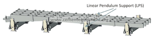
Fig. 6: Linear Pendulum Support (LPS)
The LPS had to perform a 1.5 million stroke test run with a simulated clinker
bed.The optimum layout and its durability were confirmed by various tests ‘
and calculations. The first installation has been in operation since April 2003.
Grate system and Coanda-Effect
The effective conditioning of the clinker bed on the KIDS and the efficient
cooling throughout the cooler is achieved through horizontal aeration.
This is created by narrow, inclined and curved slots (Fig. 3a/b). They
generate sharp jets of air with high dynamic pressure horizontally in the
transport direction of clinker. The Coanda effect forces the jets to curve
parallel to the surface of the grate plate instead of following the direction of
the slot. Fines are swept to the clinker bed surface and the Coanda Nozzles
are completely covered by cooling air. During normal operation a
temperature of 30°C to 40°C is measured close to the grate surface making
emergency power supply to any cooling fans obsolete. A high degree of
precision in design and fabrication of the movable gaps results in the
elimination of air ducts and the return to compartment aeration after the
stationary inlet (KIDS).
9.3.5 Thyssenkrupp Polysisus AG, POLYTRACK Cooler:
The POLYTRACK® clinker cooler is a combination of a static, horizontal aeration
floor and an above-floor clinker conveying system. Its convincing advantages
are the very high clinker bed transporting efficiency and strict separation of
the functions of transportation and aeration, due to:
– Optimum transverse distribution of the clinker resulting in uniform
and efficient cooling of all particle size fractions over the entire
width of the cooler
-Extremely low overall height
– Very high thermal efficiency
– Robust, low-wear, easy-to-maintain design providing outstanding
availability and Consistent modular construction
– Moreover, the POLYTRACK® tolerates fluctuations in the
kiln process; its flexible and high-performance clinker bed
transportation system copes with even the most difficult operating
conditions
The clinker bed transportation principle:
The clinker bed transportation principle – a special feature of this clinker
cooler – is very effective: In the direction of conveyance of the clinker, transport
tracks move to and fro above the static aeration floor.
The rows of transport tracks are installed at a particular distance to each
other. Between them the cooling air enters the bed of clinker. The required
width of the cooler determines the number of transport track rows. Each row
of transport tracks spans the entire length of the cooler.
To convey the clinker bed the transport tracks are moved forward together
and are then individually moved back. By varying the transport stroke length
and frequency, the conveying speed of the clinker bed and thus the clinker
bed depth and the clinker throughput can be optimally controlled over the
entire width of the cooler.
This well-tried clinker bed transportation principle of the POLYTRACK® provides
the best preconditions for thorough cooling of all particle size fractions.
Aeration concept:
To prevent the wear of one component from affecting the efficiency or
throughput of the machine, the functions „clinker bed transportation“ and
„cooling air distribution in the clinker bed“ are strictly separated from each
other in the POLYTRACK®.
The air distribution takes place via static aeration units located between the
transport tracks. These large-area pockets integrated in the aeration floor are
permanently filled with clinker and thus provide autogenous wear protection.
Wear of the transport tracks is minimal, due not least to the robust design,
and has no effect on the aeration of the clinker bed.
Sealing concept:
Special, wear-free sliding element pairs reliably seal the few contact zones
between static and moving cooler components. Consequently, there is no
need for wear prone conveyors for evacuating clinker that has fallen through
the grate. This is a further advantage with regard to minimizing the overall
height.
The modular concept
The modules are 4.8 m or 7.2 m long and available in widths of 1.5 m/2.0 m
and 2.5 m. With small module dimension steps – of 0.5 m over the width and
only 2.4 m over the length – it is possible to precisely design coolers to suit
spatial and process technological requirements.
Particularly in the case of system conversions, these small module dimension
steps permit optimum adjustment to the given building structures without
detracting from the process technology.
The modules are preassembled in the manufacturing shop. This ensures
optimum alignment of the transport tracks and aeration units, saving time
and effort at the plant site, shortening the installation and commissioning
periods and, in the case of conversions, also reducing the plant downtime.
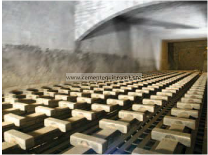
The highly effective clinker bed transportation principle, there is no need for
inclination of the cooler and the whole structure is therefore of horizontal
design.
The POLYTRACK® consequently has an extremely low construction height.
Despite the limited installation height, it is still possible to install a roll crusher
as intermediate crusher in order to intensify the cooling process.
Intermediate crusher concept:
The intermediate crusher, the cooling process on the second grate is optimised,
reducing the ultimate clinker temperature and thus also producing higher
cooler exhaust air temperatures. These higher exhaust air temperatures have
a decisive influence on the operating economy of cooler waste heat utilisation
systems (e.g. heat utilisation for power generation; heat utilisation for drying
etc. The exposed hot interior of the clinker broken by the intermediate roll
crusher is effectively cooled on the second grate and the extracted heat is
transferred to the cooler exhaust air.
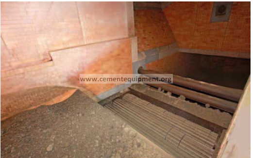
9.4 Increasing pet coke consumption as a fuel:
Petcoke is characterised as a high grade fuel with high calorific value of more
than 8,000 KCal per kg, having low ash content and low volatile matter but
high sulphur content, up to 7%.
Petcoke provides scope for manufacturing higher grade of cement with the
same raw material or same grade of cement using marginal and low grade
limestone contributing to resource conservation. Due to higher calorific value
compared to coal, less quantity of petcoke needs to be moved from source to
plant site, which reduces the cost of transport.
However, as the sulphur content in petcoke is high, its larger use increases
the sulphur cycle and aggravates build-up formation in the kiln system. The
total sulphur content in the clinker needs to be maintained below 2 per cent
from product quality point of view. For using petcoke in the cement industry,
there is, therefore, a need for changes in raw mix design and finess of fuel and
modifications in burner, calciner and cooler so that a trouble-free and cost
effective operation is achieved.
Recent studies have shown that fuel costs can be reduced by promoting the
use of petcoke. Fuel alone accounts for about 40% of the cost incurred by the
cement industry.
Alternate fuels like petcoke can reduce fuel costs to a great extent. Studies
shows that green delayed petcoke is suitable for use in calciner, fluid petcoke
is suitable for use in burning zone and calciner.
Petcoke should be used when the plant is equipped with multi-chanel burner,
when alkali deposits are high, when there is a margin in coal milling capacity
and primary air fan quantity and when riser duct is fitted with coating repellent
refactory.
Studies form the plant 1 and plant 2 shows that almost more than 80% of the
fuel is pet coke only. These plants changed their raw mix design analysis of the
average kiln feed and clinker is given below.
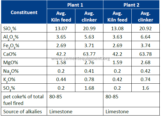
It is observed that there is no aggrevates build up in the kiln/preheater after
changing the raw mix design. Multi channel burner is used to fire pet coke and
burner momentum increased to 1790 % m/s. Incase if alkali% in limestone is
less then alkaline Feldspars added as an additive to fire higher amounts of pet
coke firing in kiln and caliner.
Some of the plants are operating with 100% fuel as pet coke without any
aggrevates build up in Kiln/prehear.