Contents
Everything you need to know about Rings, Balls and Build-Ups
1. INTRODUCTION
Rings and deposits are accumulations of solid materials (from the powdery kiln charge) in the rotary or static sections of clinker production lines. They have been encountered since the earliest days of rotary kiln production, with each development in process technology, e.g. grate and cyclone pre-heaters, grate cooler, bringing with them their own specific type of deposit.
Rather than being of academic interest, ring and deposit formation has an appreciable influence on plant operations, frustrating operations personnel by their impairing or even impeding production, and annoying the company management by lowering production (and sales) and increasing production costs.
As a direct consequence of rings and deposits, the gas and material flow through the kiln is restricted, resulting in a reduced kiln output. Especially in the sinter zone, the presence of rings can interfere with combustion of the fuel and can result in improper combustion. From time to time unstable rings and deposits can break away leading to blockage or mechanical damage in the cooler, or in cyclone blockages. The partial shedding of coating from the exhaust fan blades results in severe vibration which mostly requires a short shutdown for complete removal. The breaking of a ring almost always causes a flush of material into the burning zone and a temporary loss of stable kiln operations.
The formation of deposits in cyclones results in extra costs for the labour needed to remove the deposits by poking. The introduction of air canons (big blasters) provides a method for their regular automatic removal and has been installed in Group plants with persistent pre-heater blockages. High pressure water jets may also be employed.
In the worst cases, a complete shutdown is necessary to allow entrance to the affected area and mechanical removal of the blockage with compressed air drills. This shutdown invariably weakens the sinter zone refractories, and accelerates the next shutdown for rebricking.
2. LOCATION OF RINGS
2.1 Classification
Unwanted build-ups may be classified with regard to the type of material from which they are formed, either sintered or unsintered. Within these two groups the various types can be classified as follows:
unsintered:
• exhaust fan deposits
• cyclone and grate preheater deposits slurry or mud rings
• meal rings
sintered:
•middle ring
•sinter ring
•clinker ring
•”snowman” in grate cooler kiln charge ball
Process technological characteristics of such build-ups e.g. kiln type, location, temperature of gas and kiln charge can be seen in Table 1. Material technological characteristics e.g. state of kiln charge, enrichment in various elements, and type of texture are summarised in Table 2.
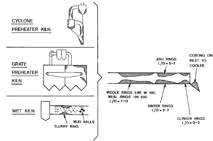
The location of the various types of the above rings and deposits can be seen in Fig. 1.
Fig.1 Rings and Build-ups in Different Kiln Systems
3. THEORETICAL ASPECTS OF RING AND DEPOSIT FORMATION
Although of much practical significance, little quantitatively based, fundamental knowledge is available on the formation of deposits from solids suspended in gas streams. In a qualitative way, however, the more important features of such processes are known.
The formation of a deposit is always a dynamic process in which the factors responsible for formation outweigh the forces of degradation. In general, the stronger the forces of destruction, the more unlikely the chance of deposit formation, but when this does occur, a strong, hard to remove agglomeration is the result.
After the transport of material to the area of deposition, a definite force is required to make it adhere to the wall. This can range in magnitude from that caused by turbulence within the gas stream, increasing to centrifugal forces when the stream changes direction, to that due to mechanical pressure. Whereas pre-heater deposits involve the first two, mechanical pressure certainly plays a part in ring formation within the rotating kiln.
The forces according to Rumpf considered to cause deposit formation can be grouped as follows:
a) melting or softening of surface due to friction or collision
b) melting or freezing due to addition or removal of heat
c) interlocking of aggregates built up of finer particles held together by surface forces
d) interlocking of long fibrous particles
e) electrostatic attraction
The mechanisms b, c and d are the ones encountered in kiln operations. In general, the finer the powder, the greater the tendency towards agglomeration, and in many cases the absence of particles under a critical size (e.g. 5 um) ensures freedom from deposition.
4. CHARACTERISTICS OF VARIOUS RING AND DEPOSIT TYPES
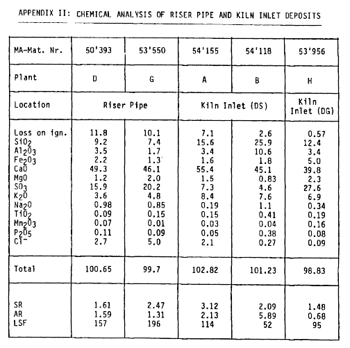
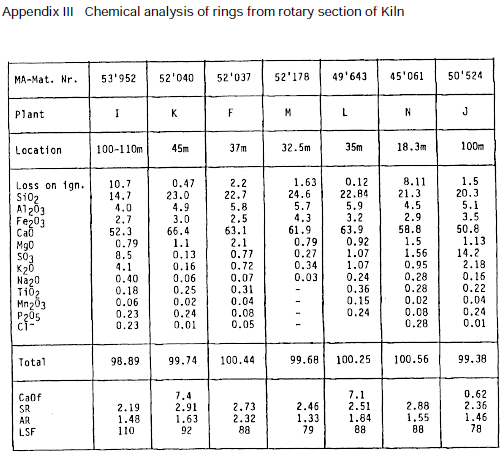
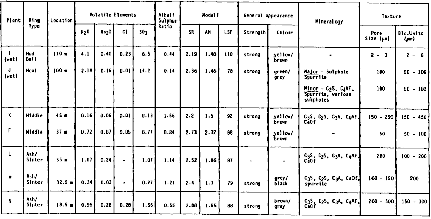
Tables 3 and 4 contain a list of typical properties of rings and build-ups encountered within the Holcim Group plants (with full chemical analysis being provided in Appendices I, II and III). Included are such factors as volatile element concentrations and moduli of the deposited materials. As an indication of the texture, the size of the pores and the particles or aggregates of particles, from which the materials were built up, is given. In many cases the mineralogical composition is also given.
4.1 Exhaust Fan Deposits
In the case of kilns with pressure filter systems, in which unfiltered dust-laden gas passes through the exhaust gas fan, deposit formation causes problems. These arise when the deposit falls off one blade, and brings the rotating fan out of balance. Deposits of up to 3.5 kg/blade are known to occur.
4.1.1 Characteristic properties:
Exhaust fan deposits, composed of the finest raw meal particles are usually red-brown, hard and quite brittle. They exhibit a compact layered structure and have a very low porosity of 8%.
Their chemical and mineralogical composition is basically that of the raw meal but often the plate-shaped clay particles are preferentially deposited parallel to the blade surfaces. Due to their long stay in the system, fan deposits are enriched in the volatile components K2O, Na2O, SO3. Typical values include the following:
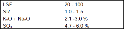
The SO3 is usually present as anhydrite (CaSO4).
Binding mechanism:
In this case, the temperature is such that liquid phase involvement – aqueous or molten salts – can be ruled out.
The dust particles, because of the fan rotation, strike the blade surfaces with a high velocity and are so compacted. As the texture of the surface, after even a short time in operation, possesses undulations in the order 0.5 – 20 um, the smaller dust particles can be mechanically “locked-on”. Subsequent development of the deposit follows by an identical mechanism.
4.2 Slurry Rings (including mud balls)
Characteristic properties:
These occur in long wet kilns and are composed of the partially dried kiln charge somewhat enriched in alkalis and SO3. They are soft and can usually be broken – and hence prevented by – heavier chains. The H2O content lies between 20 and 30%, a range in which clay materials exhibit a sticky, plastic consistency. The content of the alkalis which greatly increases the tendency to adhesion (influence on rheological properties) can be up to 10% K2O + Na2O, and about the same level of SO3. In many cases, balls form (in addition) on the chain links by the same mechanism. A typical example of a mud ball is plant I in Table 4.
Binding mechanism:
The binding mechanism is the well known ability of clays to form a sticky, plastic mass when containing the correct quantity of H2O, and to harden on the further water loss. To this mechanism must also be added the crystallization of K2SO4 solution and the further strengthening of the structure by formation of CaSO4. Photo 1a gives an example of such a ring.
4.3 Cyclone and Grate Preheater Deposits
Characteristics:
These deposits form on the roofs, walls, outlet and riser pipes of cyclone preheaters, in the hot chamber of grate preheaters, and vary considerably in appearance and homogeneity. In general, they have a light colour varying from cream to brown to pink, indicating that the component particles had not been heated higher than 1200°C. In some cases, darker zones of harder burnt material can be observed. Depending on their place of deposition, they range from a dense, compact, definitely layered structure, hard to break to a porous (30%) material with only moderate strength with less obvious layering. The former type is typical of cyclone cones and discharge pipes while the latter is to be found in the transition and swirl chambers. Soft deposits can, however, also be found in the cyclones.
From a chemical viewpoint, this deposit type usually is characterized by a concentration of the volatile elements in the following range:
K2O = 1 – 30%
SO3 = 1 – 35%
Cl = 1 – 25%
Na2O = 0 – 2%
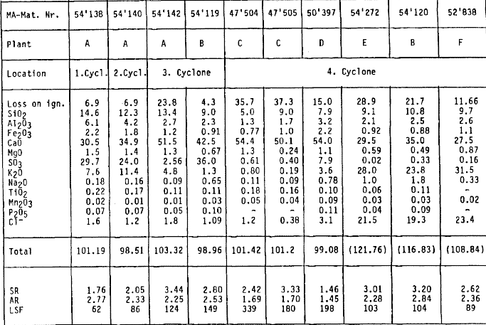
In some cases, therefore, deposits can occur with no appreciable increase in concentration. Typical analyses found for deposits are given in Table 3 and Appendix I.
The mineralogical composition of preheater deposits differs as would be expected from that of the raw meal in that the clays are essentially decomposed, and a reaction to form intermediate minerals has taken place. Minerals containing only the volatile elements can also be found.
Amongst the minerals found in preheater deposits are the following:
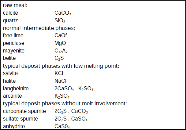
Formation mechanism:
The binding substance in this deposit type is the low melting point Na2O, K2O, SO3, Cl based compounds. These are molten in the kiln gas and are deposited on the cyclone walls and pipes, or first on dust particles which then themselves are deposited out of the gas stream in these areas. Cooling on contact or with increasing thickness results in an appreciable strengthening of the originally sticky deposit. Because of the extensive duration of stay in the kiln system, a reaction takes place with gaseous CO2 and SO3, resulting in the formation of lath shaped spurrite and sulfate spurrite which additionally strengthen the texture. Typical textures for unsintered, pre-heater and kiln inlet deposits can be seen in photos lb – ld.
4.4 Meal Ring (Calcining Ring) in Long Kilns
Characteristics and formation:
The meal rings, often called “calcining rings” in long kilns, are in their properties and mechanism of formation very similar to those of pre-heater deposits in heat exchanger kilns. This is perhaps not surprising in that both build-ups occur in the same temperature zone. Meal rings are mostly less troublesome than pre-heater deposits because often, due to their relatively poor strength, thermal fluctuations, kiln deformation and the action of the material stream, they fall off periodically under their own weight. A typical example of a calcining ring is plant J in Table 4.
4.5 Middle Rings in Large Pre-heater Kilns
Characteristics:
Unlike meal rings, middle “rings” are dense (fine grained) of low porosity, very hard and seldom fall off during operations. Although termed as a ring they are rather more elongated, like a band, being often some 15 – 20 m long extending from 7 to 11 diameters from the outlet, e.g. 35 – 55 m for a 5 m kiln. Unlike previous types, this deposit is clinker like in colour indicating it being composed of well burnt kiln charge. Perpendicular to the direction of deposition, the fine layered structure can be seen showing the curvature of the kiln shell.
The chemical composition of middle rings is very similar to that of clinker. This is surprising because considering the long duration of the stay in the kiln, no increase in concentration of the alkalis or SO3 takes place, and often the ring shows lower volatile element values than for clinker. Typical analyses of a middle ring are given in Table 5.
The minerals found in middle rings are the clinker minerals elite, belite, aluminate, ferrite and free CaO, the elite having often decomposed into microscopically mixed belite and free CaO, resulting from the temperature at the site of the ring being under the lower stability temperature of elite (i.e. 1260°C).
Formation Mechanism:
The mechanism of bonding is the freezing of the clinker alumino-ferrite melt. Due to a long cool flame, the clinker has a tendency to be fine, and the smallest clinker particles of 150 – 450 um are carried back by the flame and deposited onto the kiln wall in a zone where temperatures of below 1250°C exist. The particles immediately freeze in place, and because the kiln charge is still fine, it does not possess sufficient abrasive action to remove the growing ring. The typical compact structure of a middle ring can be seen in photo 1e.
4.6 Sinter Rings (excluding coal-ash rings)
Characteristics:
These occur at the beginning of the sinter zone some 4 – 5 D from the kiln outlet. They are greyish-black in colour, strong and are (usually) agglomerations of small clinker pellets and clinker dust. No layer structure is obvious because of the presence of large pores and voids.
In general, the chemical composition is that of the clinker with no appreciable concentration of volatile elements.
From a mineralogical viewpoint, the normal clinker minerals elite, belite, aluminate, ferrite and free CaO are observed, with reactions to form belite and CaOfree, spurrite and belite being found with increasing depth in the ring, i.e. decreasing temperature, similar to the case of middle rings.
Bonding mechanism:
The bonding is created by the freezing of the alumino ferrite clinker liquid in the case of pure sinter rings. This phenomenon occurs especially at the beginning of the sinter zone, where the liquid phase is just starting to form (approx. 1280°C). Due to the rotation of the kiln, the charge in this zone freezes with each kiln revolution: a new wet layer sticks on, and with time a thick deposit builds up consisting of particles of less than 1mm.
4.7 Coal Ash Sinter Rings
Characteristics:
In kilns fired with a high ash content coal, sinter/coal ash rings can form at 7 – 8.5 D from the kiln outlet. They are dense, often layered and sometimes glassy in appearance and built up from particles some 150 250 um in size. They are rather less dense and have larger pores and voids than middle rings. Photo 1f gives an example of the microstructure of such material, showing the coal ash layers.
From the viewpoint of their chemical and mineralogical composition they are essentially similar to clinker, exhibiting the minerals elite, belite, aluminate, ferrite and free CaO. With decreasing temperature (increasing ring depth) reactions to form spurrite and calcite take place, and also the transformation of alite belite + CaOf and belite belite. Details of the chemistry and mineralogy are given in Table 6 . No enrichment of the volatile phases can be observed. Because of the enrichment in coal ash, the belite content is higher than that of the clinker, and tends to be found in layers.
Formation mechanism:
The bonding medium here is the sticky molten coal ash particles and perhaps to a slight extent, the alumino ferrite clinker liquid phase occurring by a mechanism such as in Fig. 2 showing the typical build up during kiln rotation.
Fig. 2: Mechanism for ring formation
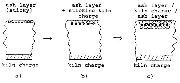
The molten coal ash droplets adhere to the exposed kiln lining at a point and temperature at which they are still partially fluid and sticky. When this sticky layer passes under the kiln charge on each rotation, it is assumed that a single layer of the still very fine kiln charge adheres to it. Because of the presence of fine crystalline elite and the overall occurrence of liquid phase, it must be assumed that the material temperature at the position of the ring lies above 1260°C.
The elite crystals are very small and certainly much smaller than those of the clinker. Because of this, it can definitely be said that the ring is not formed from clinker dust blown back down the kiln.
4.8 Clinker Rings / Cooler Inlet Deposit (snowman)
Such rings and deposits are formed from normal size clinker granules and have a high porosity containing many voids. They are usually not troublesome to kiln operations as they can easily be removed. Their composition and mineralogy is identical to clinker, but in some cases, rings of up to 3.5% K2O and 3.0% SO3 have been observed.
The mechanism of bonding is the freezing of the clinker liquid phase as the clinker passes through the cooling zone (ring) or on falling down the chute into a grate cooler, grate kilns being usually operated so as to have no cooling zone within the kiln itself.
4.9 Kiln Charge Balls
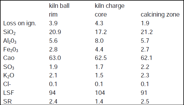
Kiln balls occur in cases where a tendency to meal or sinter ring already exists and can be up to 1m in diameter. The chemical composition is, thus, an important factor. They are usually found upstream of meal or sinter rings. They are usually made up of already calcined material and can have a porosity of up to 55%, consisting of many fine pores. Often they consist of a hard dense porous core, surrounded by the majority of porous material. The core usually is a piece of coating from say the lower heat exchangers or the transition chamber, and often has a come position different from the kiln charge in the area of formation. Differences in composition can be seen in Table 7.
The mechanism of meal ball formation can be due to either, or a combination of the following factors:
• stripping and subsequent “balling” of old, excess coating
• agglomeration enhanced by available clinker and/or salt melt
• ring section acts as a dam, retaining “pieces” of material for long periods. Radial growth of the pieces occurs by compaction and adherence of fresh surface due to continual rolling action of the pieces/balls over the charge.
In most cases, no liquid phase participation in sufficient quantities is possible so that the balls behave like a snowball and by their own pressure material sticks to the surface. This mechanism is similar to that of deposition on the exhaust fan blades.
5. METHODS OF REMOVAL/ELIMINATION
An important prerequisite for minimizing the tendency to form objectionable coatings and rings, is stable kiln operation. This applies to the composition, fineness and feed rate of the raw material and fuel, and burning zone heat control.
The tendency to form coatings in the kiln is reduced by lowering the dust load of the kiln gas.
Objectionable coatings and rings which are formed as a consequence of high concentrations of various circulating elements can be obviated by appropriate reduction of the cycles in question.
This can be achieved by:
• Employing different raw materials and/or fuel with lower concentration of the offending element. This is generally not practicable.
• Control of the raw meal milling so as to reduce the concentration of the very fine particles of sizes under 20 m.
• Intervention into cyclic process by either discarding dust in which the circulating elements have become concentrated, or by means of a bypass installation which extracts a portion of the kiln gas.
The penetration of false air into the preheater and kiln inlet chambers should be avoided, as such cold areas will act as sites for preferential build-up.
In order to reduce the tendency to form sinter rings, it is in the first place necessary to reduce the proportion of fusible matter in the clinker, i.e. the lime standard and silica modulus should be increased. “Coating-inactive” bricks have also proved successful in certain cases, in reducing the tendency toward sinter ring formation.
In coal-fired kilns a coal with a normal ash content should be employed as coals having ash contents of 40% are characterized by a very high tendency to ring formation. No general approach can be given to the effectiveness of other measures, e.g. alteration to firing conditions, as these represent variables which are peculiar to the particular installation.
Clinker rings can be avoided by shifting the flame further back, thus increasing the clinker temperature at the kiln outlet. As a result of this, however, the “stickiness” range of the clinker is shifted towards the cooler inlet. Coatings can then be formed on the cooler inlet chute. This is particularly problematic with satellite coolers. In instances where this occurs with grate coolers, these coatings can be eliminated by the use of water cooled plates on the inlet chute.
Table 1 Time and Location of Rings and Coating (according to Opitz, 1974)
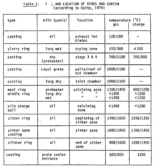
Table 2 General Characteristics of Various Ring Types
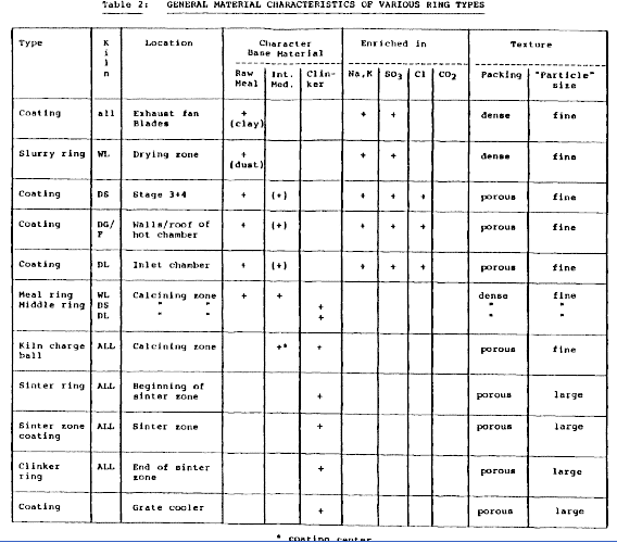
Table 3 Properties of Build-ups Examined
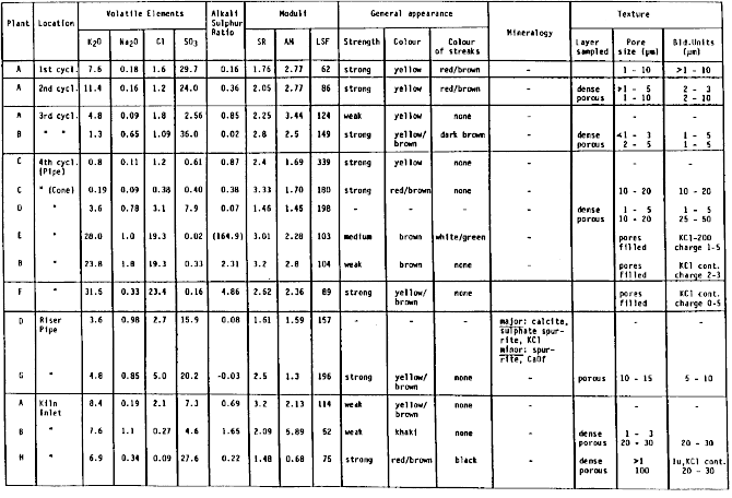
Table 4 Properties of Rings Examined
 `
`
Table 5 : Typical analyses of a middle ring at various depths
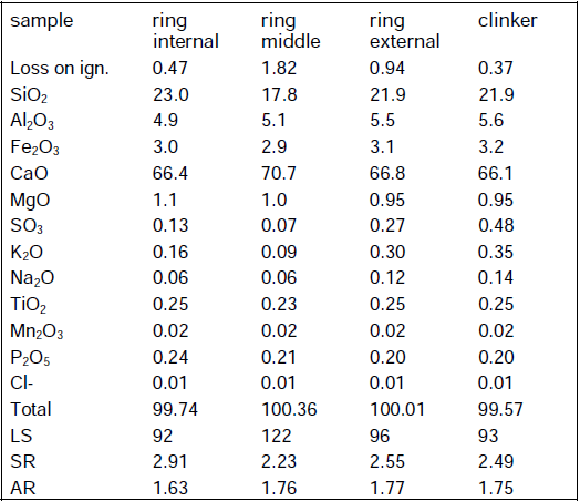
Table 6: Chemistry and Mineralogy of a (coal ash) ring
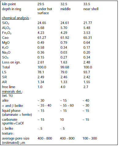
Table 7. Chemical comopsition of core and rim of meal ball and the kiln charge composition at the corresponding zone
Appendix I: Chemical analysis of preheater cyclone deposits