Contents
BUCKET ELEVATOR HP AND SHAFT CALCULATIONS
HORSE POWER AND CALCULATIONS
A bucket elevator is a complex system with many variables to consider. As discussed in previous chapters these include bucket size, bucket spacing, speed, and various components. Some of the most critical, and sometimes hard to understand principles of bucket elevator design include the sizing of the motor and shafts. These components require a detailed look into their sizing and selection. Utilizing the information contained in this chapter one should begin to gain a basic understanding of the various factors which influence the design of these components.
When designing a bucket elevator there are more variables to be considered than can be listed in this publication. Many bucket elevators are very tall and heavy and pose a significant safety risk if there are not implemented correctly. In addition to proper design of the components listed here proper casing design (chapter 5) is also critical to the successful and safe operation of a bucket elevator. Because of the severity of failure of these key components and complexity of design it is important to always work with an experienced bucket elevator manufacturer who can help in the design and implementation of a successful bucket elevator project.
Determining Horse Power
In order to accurately determine the power requirements of a bucket elevator, the internal forces acting on the unit must first be understood. Although there are many components in the bucket elevator, only the upward movement of the conveyed product needs to be considered. This is because the weight of the belt and buckets are identically balanced on both sides of the head shaft. Only the internal friction caused by the movement of these components needs to be considered when calculating the HP requirements.
There are many variations of Horse Power (HP) calculations found in historical and individual manufacturer’s literature. The formulas below are used to determine the power requirements of a bucket elevator throughout the industry. Although references are made to belt and pulley style bucket elevators, the principles of design contained in this chapter apply to sprocket and chain style bucket elevators, as well.
A basic power calculation is the measure of force over a distance per time period.
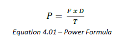
Where:
P = Power
F = Force
D = Distance
T = Time
In a bucket elevator the power requirement can be directly calculated using this formula.
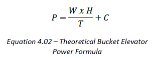
Where:
P = Power to convey the product
W = Weight of material being lifted
H = Lift Height
T = Time
C = HP required to overcome the friction in the system.
The frictional losses in the system come primarily from the following factors:
• Drive Inefficiencies
• Belt slip on the head pulley
• Chain slip on sprockets
• Bearing friction
• Digging by elevator buckets in the boot
When designing relatively small bucket elevators, the digging losses can be the most significant of these factors. When designing taller bucket elevators with larger drives, the drive inefficiency is usually emphasized.

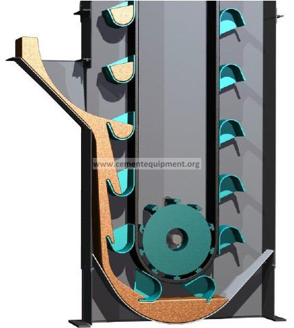
Figure 4.01 – Bucket Digging
Digging losses can be estimated using the length equivalency method. This method is used to account for the frictional horsepower loss caused by the buckets digging material as they pass around the tail pulley and is calculated by multiplying the “length equivalency factor” or Leq by the diameter of the boot pulley and adding it to the lift height (H) of the bucket elevator. The Leq is a usually between 5 and 15 and depends upon the application. Consult your CEMA bucket elevator supplier for additional information about this factor.
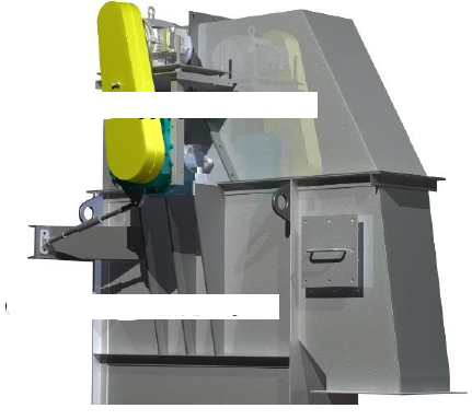
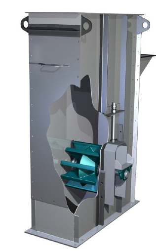
Figure 4.02 – Bucket Elevator Shaft Mount Drive
Drive inefficiency and other frictional losses that grow in proportion to the drive size are reflected by the efficiency factor, Ceff. The value of Ceff varies between 1.1 and 1.3 depending upon the drive configuration and other factors. Note that motor inefficiency is NOT included because these formulas are used to determine the motor size. Motor HP ratings include their inherent inefficiencies. Again, consult your bucket elevator supplier for further information.
Using equation 4.02, substituting the gravimetric flow rate of a bucket elevator and adding the terms for frictional losses, the following equation can be derived.
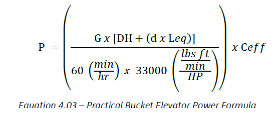
Where:
P = Power (HP)
G = Gravimetric Rate (lbs per hour)
DH = Discharge Height (ft)
d = Diameter of tail pulley (ft)
Leq = Length equivalency factor (ft)
Ceff = Efficiency factor (dimensionless)
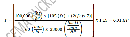
Using the above formula the following example can be solved for horse power.
Example 4.1:
A Customer would like to convey 100,000 lbs per hour of sand to a height of 105 feet. Determine the required HP.
Solution:
Given:
Rate (G) = 100,000 (lbs per hour)
Discharge Height (DH) = 105 (ft)
Tail Pulley Diameter = 2 (ft)
Length equivalency factor (Leq)= 7 (Assumed)
Efficiency factor (Ceff)= 1.15 (Assumed)
Headshaft Design
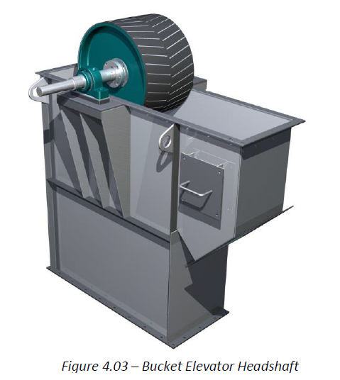
The bucket elevator’s headshaft diameter should be designed with consideration of the loads that it bears and also for the consequences of its failure. Because the headshaft supports the weight of the belt, buckets, and material being elevated, a broken headshaft can release significant potential energy. On larger elevators, a broken headshaft can be catastrophic. In addition to the safety concerns, replacement of a broken headshaft is difficult because the belt, buckets, and shaft mounted drive must be supported while the broken headshaft is extracted and replaced. On a large elevator, this usually necessitates the use of a crane. Due to the critical nature of this component, a generous safety factor is recommended.
Below are the calculations for the maximum stress and deflection the shaft will see based on the loading of the head pulley, belt, buckets and material being lifted. Both calculation sets should be performed on the headshaft. The calculation which yields the largest required shaft diameter should be utilized for the bucket elevator design. Note that it is never advisable to use a bearing diameter less than the pulley bushing diameter. To do so would require a stepped shaft which would place a stress concentration in a critical area. Additional Information about proper bearing selection can be found in chapter 5.
The formulas included here can also be utilized for a bucket elevator design to use chain and sprockets instead of belt and pulleys as discussed. In addition, some small pulleys only utilize a single bushing, instead of the double bushing shown.
Headshaft Design for Stress
As discussed above the design of the headshaft for a bucket elevator is one of the most critical calculations for a proper design. The first criteria to evaluate is the maximum stress in the shaft. The formula below is a conservative approach to shaft design and a generous safety factor should be utilized. In addition, the formula below does not account for a large drive being overhung outside of the bearing centerlines. Large overhung loads will need to be evaluated in a method separate from the information provided in this guide.
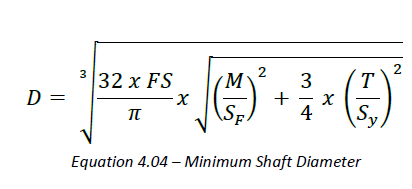
Where:
D = Minimum Shaft Diameter (in)
FS = Factor of Safety
M = Bending Moment (In-lbf)
Sf = Corrected Shaft Fatigue Limit (lbf per square inch)
T = Torsional Moment (lbf-in)
Sy = Maximum Shear Stress (lbf per square inch)
The corrected shaft fatigue limit is adjusted for the conditions of the material used to make the shaft utilizing the following factors
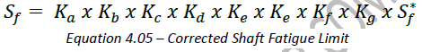
Where:
Ka = Surface Factor (0.8 for machined shafts)
Kb = Size Factor (D-0.19)
Kc = Reliability Factor (0.897)
Kd = Temperature Factor (1.0 for -70ºF – 400ºF)
Ke = Duty Cycle Factor (1.0, provided stresses do not exceed Sf)
Kf = Fatigue Stress Concentration Factor:

Where:
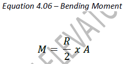
M = Moment (in-lbf)
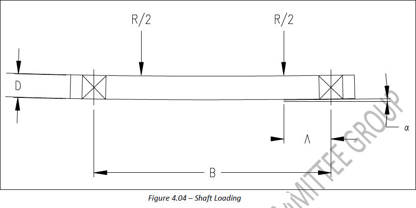
R = Full load directed downward on headshaft (lbs)
A = Distance between the pulley bushing and the headshaft bearing center (in)
To solve this formula, it is necessary to determine all of the loads acting on the headshaft (R) at the pulley bushing locations. Usually the belt tension is calculated from three components: T1, T2, and T3. T1 represents the tension due to the weight of the product being elevated. T2 represents the weight of the up side belt and buckets. T3 represents the slack side tension necessary to prevent belt slippage against the head pulley. The only other load to be considered is the weight of the head pulley itself.
The formula for headshaft loading at the pulley bushings can be written:
𝑅 = 𝑇1 + 𝑇2 + 𝑇3 + 𝑃𝑊
Equation 4.07 – Headshaft Loading
Where:
R = Full load directed downward on headshaft (lbs) T1 = Weight of material being lifted (lbs)
T2 = Weight of up side belt and buckets (lbs)
T3 = Slack side tension (lbs)
PW = Weight of the head pulley (lbs)
The belt tension component due to the weight of material being elevated, T1, can be written:
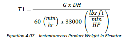
Where:
T1 = Weight of material being lifted (lbs)
G = Gravimetric Flow Rate (lbs per hour)
DH = Discharge Height (ft)
T2 represents the weight of the up side belt and buckets. Note that we are not concerned with the weight of the down side belt and buckets since they are subsumed by T3. T2 can be written as:
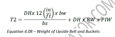
Where:
T2 = Weight of Up Side Belt and Buckets (lbs)
DH = Discharge Height (ft)
bw = Weight per bucket including hardware (lbs)
bs = Bucket Spacing (in)
BW = Belt Width (in)
PIW = Weight of Belting (lbs per inch width per linear foot)
T3 represents the minimum tension required to prevent belt slippage against the head pulley. Special consideration should be taken for take-ups which will exert force in addition to that calculated in formula 4.14. The K factors were empirically determined some time ago and their source is unknown. They are commonly used and range from 0.5 to 0.9. T3 can be written as:
𝑇3 = 𝑇2 + 𝑇1 𝑥 𝐾
Equation 4.09 – Slack Side Tension
Where:
T3 = Slack Side Tension (lbs)
T2 = Weight of Up Side Belt and Buckets (lbs)
T1 = Product Weight in Up Side buckets (lbs)
K = Take-up Tension Factor
The Torsional Moment (T) is the force excreted on the headshaft by the drive and is defined as:
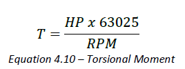
Where:
T = Torsional Moment (Lbf-in)
HP = Horse Power of the Motor
RPM = Revolutions per Minute of the shaft
Drive Considerations
There are many drive types employed on bucket elevators. While a shaft-mounted gear drive is most typical, other configurations such as chain drives, and support stand supported drives also exist and are widely used. Due to variations of drive types and mounting configurations, it is not possible to include a comprehensive shaft design analysis in this document. Significant forces that should be considered include:
• Reaction force from the torque arm of shaft mounted drives
• Chain tension from chain drives
• Weight of shaft mounted drives
Headshaft Design for Deflection
CEMA pulley standards specify a maximum shaft slope measured at the pulley bushings of 0.0015 in/in. The intent is to minimize the bending moment being applied to the pulley end discs through the connection to the shaft. In some cases, the minimum shaft diameter to meet this deflection criteria will exceed the shaft diameter calculated using a maximum stress approach. In this cases, it is recommended that the larger of the two diameters be selected.
The shaft slope at the pulley bushings can be determined from the following formula.
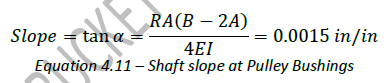
Where:
𝛼 = Angle Shaft Deflection
R = Full load directed downward on headshaft (lbs)
A = Distance between the pulley bushing and the headshaft bearing center (in)
B = Distance between headshaft bearing centers (in)
E = Modulus of Elasticity of the headshaft material (psi)
I = Moment of inertia of shaft cross-section (in4)
Using equation 4.11 we can insert our known variables and solve for minimum headshaft diameter, D, which satisfies the CEMA shaft slope criteria.
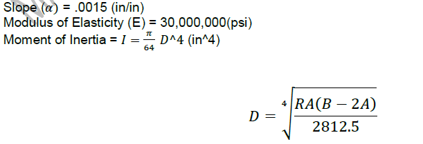
Equation 4.12 – Minimum shaft diameter to satisfy CEMA Pulley criteria
Determining Bootshaft Diameter
The bootshaft is the shaft in the boot supporting the tail pulley of the bucket elevator. The bootshaft is not subjected to the same loads as the headshaft. Since there is no torsion we are only concered about the bending moment excetrted on the shaft. Because of this the stress formula shown above (formula 4.04) can be simplified as follows.
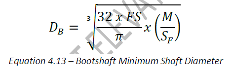
Where:
DB = Minimum Bootshaft Shaft Diameter (in)
FS = Factor of Safety
M = Bending Moment (In-lbf)
Sf = Corrected Shaft Fatigue Limit (lbf per square inch)
Formula 4.6 for the bending moment is utilized in the above formula, however the resultant load (R) on the bootshaft is expressed as:
𝑅𝑏=𝑇1 𝑥 𝐾−𝑃𝑊
Equation 4.14 – Bootshaft loading formula
Where:
Rb = Bootshaft Load (lbs)
T1 = Product Weight in Up Side buckets (lbs)
K = Take-up Tension Factor
In general, the loads imposed on the bootshaft are very low when compared to the headshaft. Special consideration should be taken for take-ups which will exert force in addition to that calculated in formula 4.14. Most manufacturers will us a simple rule for the bootshaft diameter to be some fraction of the diameter of the headshaft.
thank you for the information