Contents
Everything you need to know about Modeling in Cement Kiln Operations
[wpecpp name=”package” price=”75″ align=”center”]
by Georg Locher* and Martin Schneider*
Mathematical modeling of production processes is already far advanced in many branches of industry, but so far very few approaches exist for the clinker burning process during kiln opera-tions in cement industry. An important reason for this is the complexity of the heat transfer about which comparatively little is known, and which takes place simultaneously with chemical, physical, and mineralogical reactions. Operational measurements to investigate the processes are compli-cated and in many cases not yet technically possible. In particular, this includes measurement of the heat transfer in rotary kilns and calciners, and of the heat transfer between gas and kiln feed in the individual cyclone stages as well as between cooling air and clinker in the grate cooler.
Nevertheless, many of the phenomena relevant to the clinker burning process have been investigated individually in detail. These include, for example, calcination, clinker phase formation, combustion of fuels, and heat transfer in packed beds. These processes are now sufficiently well understood to be able to develop mathematical expressions and compare their results with practical measurements. They can be combined to form a complete model so that the interactions between plant sections and individual reactions can also be taken into account.
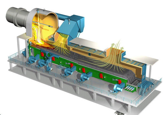
The model described here includes the phenomena from the entry of kiln feed to the discharge of clinker from the cooler, and covers process engineering, material, and thermal phenomena. The emphasis is on the interactions between the processes, which is why the modeling of the individual plant components is kept simple at first. An example of mathematical modeling based on heat flow between kiln feed and gas in a segmented rotary kiln is shown in Figure 10.2.1. In many cases it can be refined, but this would lead to unacceptably long calculation times. At present it takes 15 to 30 minutes (Pentium III, 800 MHz, Windows NT) for calculating the steady-state condition for a complete plant consisting of preheater, calciner, bypass, kiln, and cooler –with the result that it is still possible to carry out calculation studies with parameter variations.
It is not the aim of the work introduced below to adapt the model empirically to measured data. The results so far show that this would certainly be possible with a few additional parameters. The intention is rather to investigate the extent to which the current understanding of the process is appropriate and complete. A comparison between calculation and measurement indicates that deviations can generally be attributed to phenomena which were not adequately taken into account during the modeling. Against this background a gain in understanding can be expected only when the corresponding differences are worked out and explained, and are not obscured by parameters that have no reference to the phenomena in the process.
An important aim of the work is use of the calculations to optimize the clinker burning process. This relates, for example, to a changed mode of operation of the plant, the use of secondary materials, plant modifications, and measures to increase efficiency. The best possible agreement between the model and reality is an essential precondition.
BACKGROUND AND PREVIOUS WORK
Cyclone Preheaters
Cyclone preheaters in the cement industry operate on a principle which can be described as a combination of co-current and counter-current heat exchange. The kiln feed is fed into the gas duct of one stage, entrained by the gas during which it is heated, and finally collected in the cyclone. It then drops into the gas duct of the next lower stage, is heated further by the gas, and is collected again. As a consequence, there is co-current transmission of the heat in each individual stage, but the preheater as a whole can be regarded as a counter-current heat exchanger.
The effectiveness of a preheater can be considered against this background. In principle, a greater quantity of heat can be transmitted from the gas to the kiln feed in counter-current than in co-current. The attempt is made to achieve this in practice by using a large number of cyclones. It is also important that these cyclones separate the kiln feed and gas as efficiently as possible, as heat is carried in co-current with any kiln feed which has not been collected and, as a result, acts against the counter-current principle. The flow regime in the gas ducts and cyclones as well as the wall heat losses also influence the effectiveness of preheaters. Wall heat losses result in a direct reduc-tion in the quantity of heat which can be transferred from the gas to the kiln feed, but the flow regime influences the distribution of the kiln feed in the gas flow and hence the corresponding heat transfer.
Fundamental thought had already been given to the effectiveness of heat exchangers in the 1960s (Vogel, 1968; Hohenhinnebusch, 1969; and Frankenberger, 1969) and included not only practical investigations but also an increasing range of theoretical calculations. Vosteen (1971) was able to prove mathematically that in each stage the gas and kiln feed reach virtually the same temperature. However, the theoretical estimate did not include any heats of reaction. With increased demands on the accuracy of the investigations it was therefore necessary to take into account that the heat exchange during calcination is also affected by the reaction kinetics (Vosteen, 1974; Reh, 1983; and Rosemann, 1986a). Clinker phase formation, which can be associated with a considerable contri-bution to the heat balance, may also occur (Rosemann, 1983).
The quality of heat exchangers depends on the quantity of heat transferred and was investigated mathematically at an early stage (Frankenberger, 1970; and Ritzmann, 1971). However, it cannot be measured directly in the cement manufacturing process, since not only the sensible heat but also the heat of reaction has to be taken into account, which requires determination of the composition of the kiln feed as well as the temperature. These calculations are made even harder by the fact that substantially calcined dust is entrained in the kiln exhaust gas mixes with the kiln feed in the pre-heater and simulates too high a degree of calcination in the preheater. Vogel (1968) investigated these relationships to prove the dependence of the degree of calcination on the dust transport in the preheater.
Rotary Kiln
Rotary kilns in the cement industry operate on the counter-current principle. In the dry process the hot meal which has been between 50% and more than 90% calcined, depending on the preheater, passes counter-current to the hot process gases. During this process it is heated from about 900°C to 1500°C, during which the chemical and mineralogical transformations necessary for cement clinker formation take place. The necessary energy is provided by the combustion of fuels.
The heat transfer between kiln feed and gas takes place both directly and indirectly and is made up of convection and radiation components. With direct transfer, the heat is exchanged directly between gas and kiln wall. The wall is also heated by the combustion gases and exchanges heat with the kiln feed both to its upper side (radiation) and during contact of the wall with the underside of the kiln feed. Heat losses as a result of thermal conduction through the kiln wall and into the surroundings depend essentially on the type and thickness of the brickwork.
The main contributions to the kiln heat balance come from combustion, calcination, formation of β-C2S, possibly vaporization of alkali chlorides, and melt phase formation. The kiln feed enters the kiln with varying levels of calcination which depend on the preheater. The length of the calcining zone and heat requirement for the remaining calcination depend on the degree of calcination on entry to the rotary kiln. Any alkali chlorides present vaporize at temperatures above 900°C to 1000°C and are carried away with the combustion gases. The heat of vaporization is expended in the kiln and released again as heat of condensation in the preheater or calciner.
The heat released during the formation of β-C2S is available in the kiln for meeting the heat requirement. Formation of the melt phase starts at temperatures around 1280°C, for which energy is required. The energy is released again in the precooling zone of the kiln and in the front of the cooler.
Measurements within the kiln and at the kiln inlet and outlet are difficult and at present are possi-ble to only a limited extent. As early as the beginning of the 1960s, Weber (1960) investigated a Lepol kiln, a cyclone preheater kiln, and a long wet kiln by placing sampling holes along the kiln axis. This made it possible to measure temperatures and take samples. Attempts were also made at an early stage to investigate the processes in the kiln mathematically. Rosa (1970) put forward a mathematical model in which the preheater, kiln, and cooler were subdivided into a total of nine zones. Conversion reactions between raw material, entrained dust, flue gas, fuel, and air were formulated for the individual zones and calculated iteratively with the aid of a computer. Frankenberger (1971) calculated an average heat transfer co-efficient for the entire kiln in order to predict specific fuel heat consumptions. Onissi (1980) drew conclusions about the temperature profile in the kiln from material investigations after kiln stoppages, and from the findings he deduced equations for dimensioning kilns. At the same time, he indicated the importance of heat transfer by radiation and its dependence on the dust loading. In the development of a mathemati-cal model Gardeik (1979a, 1979b) started initially from idealized conditions –more extensive considerations were concerned in particular with the relationship between direct and indirect heat transfer. Frisch (1983) built on this and extended the model to take into account not only the radi-ation but also chemical reactions. Parameter variations showed that the description of the material properties of the kiln feed can have considerable effect on the result of the calculation. In the work by Maas (1995) the corresponding mathematical description was refined so that the calculations could be used for designing rotary kilns. For this purpose raw meals were investigated in a gradient furnace and the results were used in the mathematical model for calculating the process engineering design variables. Nowadays commercially available programs enable extensive mixed differential algebraic equation systems for the clinker burning process to be solved with normal personal computers (Klein, 1999).
Grate Cooler
The task of the clinker cooler is to cool the cement clinker in continuous operation to the lowest possible temperature with a temperature regime adapted to suit the quality. At the same time, the combustion air required for the burning process should be preheated to a temperature level such that the kiln feed temperature required for clinker formation in the sintering zone of the rotary kiln is achieved with the lowest possible use of fuel energy.
During this process the temperature change in the clinker has an important influence on the qual-ity of the cement produced from it, especially on its composition, setting, and hardening. It is advantageous for the strength development that the clinker is not cooled too rapidly from the sintering temperature down to about 1250°C as this allows the clinker melt to crystallize in fine-grained form. On the other hand, the cooling in the temperature range between 1250°C and 800°C must be carried out as quickly as possible to prevent decomposition of the C3S. Below a tempera-ture of 800°C the rate of cooling has no further effect on the quality.
For industrial clinker cooling it is necessary to differentiate between the pre-cooling zone of the rotary kiln and the cooling in the clinker cooler. The clinker is cooled while it is still in the rotary kiln because the highest kiln feed temperature is reached at least several meters before the kiln outlet. In addition to this, the colder secondary air carries out counter-current cooling of the clinker while it is still in the rotary tube. The cooling in the pre-cooling zone is relatively slow because of the comparatively poor heat transfer and heat conduction conditions. The model presented here is based on expressions for calculating the heat transfer between particles and fluid in particulate beds and the cooling of a sphere in a stream of gas.
Complete Plant
Any ideas about optimization of the cement clinker burning process should include the complete plant from preheater to clinker cooler as the sections of plant are closely linked to one another by mass and energy flows. The investigations described in the literature focus on the expenditure of fuel energy. As a rule, the mathematical models have concentrated on the area of the preheater and calciner and have dealt with the kiln and cooler by using empirical equations.
As early as 1980, Elkjær (1980) described a model with which it was possible to calculate the heat consumption of a kiln with a four- or five-stage preheater and, where applicable, also a bypass. Parameter studies involved false air at the kiln meal feed, radiation losses, and collecting efficien-cies of the cyclones as well as operation with a bypass. Gardeik (1981a) investigated the influence of a reduced sintering zone temperature on the energy consumption of the plant and calculated a saving of about 4.5% for a reduction from 1450°C to 1250°C. Further, different modes of operation of a plant with calciner and bypass were investigated (Gardeik, 1981). It was assumed that the calculated rise in energy consumption with increasing proportion of fuel in the secondary firing system was due to a higher raw gas temperature which could be utilized with an additional cyclone stage. On the basis of a model which was not described in detail, Rother (1982) reported that an additional fifth cyclone stage can enable significant savings to be made where there are high costs for thermal energy and high proportions of fuel in the secondary firing system. Menzel (1987) compared various cyclone preheaters with one another and came to the conclusion that simpler preheater processes were to be preferred because of lower capital costs in spite of the heat technol-ogy disadvantages.
CONCEPT OF MODELING
Material, Gas, and Fuel
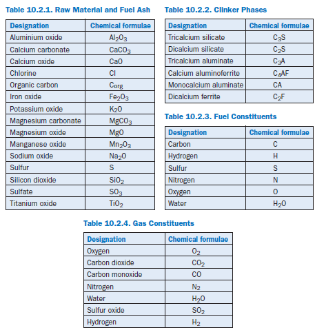
The modeling is based on material and energy balances carried out on the material flows. For the solids a distinction is made between the raw material components (Table 10.2.1), the clinker phases (Table 10.2.2), and the chemical constituents of the fuels (Table 10.2.3). Comparable consideration is also given to the individual gas constituents (Table 10.2.4).
Clinkering Reactions
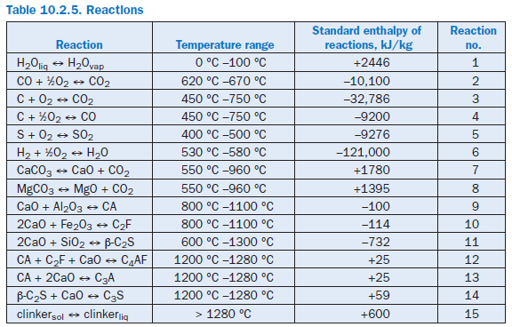
The formation of the clinker phases from a raw material mix is made up of many individual reac-tions of which the most important from the materials and energy point of view are modeled as follows (Table 10.2.5).
Evaporation of liquid water. Any liquid water which may be present (raw material and fuel moisture) is evaporated completely at a temperature of 100°C and passes into the gas phase. In the modeling it is assumed that the requisite evaporation enthalpy is not applied solely when the boiling temperature is reached, but instead is allowed for continuously during the heating in the tempera-ture range up to 100°C (Reaction 1 in Table 10.2.5).
Reaction of carbon monoxide (CO) in gas phase. According to the model, there must be a minimum temperature of 620°C for the conversion of CO to CO2.If this is the case, then the enthalpy of reaction is taken as 10100 kJ/kgCO.The quantity converted is determined by an upper limiting temperature of 670°C. Above this temperature complete conversion is assumed; at temper-atures between the minimum temperature and the limiting temperature the conversion is linearly dependent on the final temperature achieved in the reactions space (Reaction 2 in Table 10.2.5).
Reaction of organic constituents in solids. Carbon in the solids can derive both from the raw material and from incompletely burnt fuel. Depending on the supply of available oxygen and the temperature, carbon either reacts to form CO2 or CO or else may emerge unchanged from the particular balance area. According to the model, the reactions start at a temperature of 450°C and are complete at 750°C, provided sufficient oxygen is present (Reactions 3 and 4 in Table 10.2.5).
Combustion reactions. Various types of fuel can be fired in the clinker burning process. The composition of the resulting flue gases is governed by the composition of the fuel used (Table 10.2.3) as well as by the local gas composition (especially the available oxygen), and is determined in the model with the aid of chemical reaction equations (Reactions 3 to 6 in Table 10.2.5). This procedure makes it possible to cater not only for standard fuels but also for secondary fuels. The burn-out behavior is modeled by neglecting kinetic effects and forming a mathematical series-connection of several balance areas, in which in each case the calculation only covers the conver-sion of part of the total fuel used, e.g., in the rotary kiln.
The composition of the resulting flue gas is dependent on, among other things, the relevant quan-tity of available oxygen. If oxygen is present in sufficient quantity it is assumed that the carbon, hydrogen, and sulfur are fully converted into CO2,H2O, and SO2. The reactions are incomplete if there is a lack of oxygen. In this case it is assumed that the hydrogen is converted preferentially; any remaining oxygen is then credited to the reaction with sulfur. The reaction of carbon to form CO and CO2 takes place last. Any hydrogen from the solids which has not been converted in these reactions passes into the gas phase, while sulfur and carbon continue to remain in the solid phase.
The temperature of the flue gases is determined with the aid of an energy balance for the particular balance area. The first step is to calculate the composition and quantity of the flue gases resulting from the above-mentioned chemical reactions. In the next step, the quantity of heat released during combustion is determined in terms of the calorific value. When applied to the quantity of flue gas and the resulting ash, this gives the theoretical combustion temperature.
The fuel ash which mixes with the other solids in the particular combustion zone is also taken into account in the calculation. In the primary firing system, for example, it initially forms a constituent of the dust entrained in the gases before it is collected by the kiln or the cyclones of the preheater in accordance with their collecting efficiencies. It then mixes with the local stream of solids and contributes to the reactions of the solids in accordance with its composition.
Calcination. The temperature range for calcination is assumed to be between 550°C and 960 °C during which CO2 is expelled into the gas phase from CaCO3 and MgCO3. The dissociation enthalpies are taken as 1780 kJ/kgCaCO3 and 1395 kJ/kgMgCO3 respectively (Reactions 7 and 8 in Table 10.2.5).
Clinker phase formation. The clinker phases C3S, C2S, and C4AF are produced from the inter-mediate products CA, C2F, and β-C2S. The conversions and reaction enthalpies are as proposed by Rosemann (1986b) (Reactions 9 to 14 in Table 10.2.5).
Liquid phase formation. Formation of the liquid phase is assumed to take place above 1280°C (Reaction 15 in Table 10.2.5). The calculation is based on the assumption that in the temperature range between 1280°C and 1450°C, the clinker phases C3A, C4AF, and C2F pass completely into the liquid phase and that 5% of the C2S passes into the liquid phase. The enthalpy of liquid phase formation is assumed to be 600 kJ/kgliq.The temperature dependence of all material parameters (density, specific heat, thermal conductivity, dynamic viscosity) of the solids, gases, and water is taken into account with the usual polynomial expressions.
Critical Unit Operations
In the clinker burning process, finely ground kiln meal is heated counter-current to the process gases. The associated reactions are characterized at many points by the contact between kiln meal and gas, and therefore have certain chemical engineering similarities. This concerns, for example, the dispersion of kiln meal in the process gas, which is repeated many times in the preheater, calciner, bypass, and rotary kiln. The temperature and composition of the kiln meal and gas do in fact change, but the chemical engineering unit operation of dispersion of finely ground meal in gas remains the same.
This circumstance is utilized in the model by formulating the unit operations so that they are generally applicable to the entire clinker burning process. For example, the processes during the heating of a stream of solids are modeled so that they cover the entire relevant temperature range and the usual range of composition of kiln feed and gas. Because of this approach it is not necessary to stipulate at which point in the process certain reactions take place. For example, due to the local conditions it will become clear during the calculation whether the clinker phase formation has already started in the calciner or only starts in the kiln. This avoids having to make a commit-ment in advance.
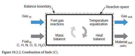
A description is given below of the unit operations which can be used to describe many phenom-ena in the clinker burning process. In addition to the unit operation for combustion of fuels (Figure 10.2.2), they also concern the material conversion phenomena and relate to any of the reac-tion spaces in the preheater, calciner, bypass, and rotary kiln. The calculations are based on the reaction equations listed in Table 10.2.5 for which the material and energy balances are drawn up and solved in the unit operations.
Heating/cooling of a stream of solids. This situation relates to a stream of solids of any composition which is being heated or cooled (abbreviation HS, Figure 10.2.3). Depending on the composition and temperature, the listed reaction (Table 10.2.5) can also take place. For example, if kiln feed of appropriate composition is heated sufficiently during calcination, this leads to the formation of CO2,which passes into the gas phase. In addition, the fact that the reactions can also depend on the composition of the gas phase is taken into account. Organic carbon, for example–depending on the total available oxygen in the gas and solids –can be converted into CO or CO2 or else, in the absence of oxygen, only change in temperature while remaining materially unchanged.
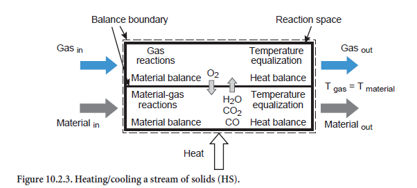
Emerging from the balance area therefore are a materials stream and a gas stream with compositions which generally differ from those of the input state. In the present situation for the unit operation of heating/cooling a stream of solids, it is assumed that the two emerging streams (gas and solids) have the same temperature, e.g. during the heating of the meal in the kiln by its long and persistent contact with the hot inner wall of the kiln. If, on the other hand, the heat is only partially transferred between gas and material, then this has to be taken into account with the aid of another unit operation as is explained in the forthcoming Section on Dispersion of solids in gas.
On the assumption that the emerging gas and the emerging solids have the same temperature, it is possible to calculate their compositions and temperature using the above-mentioned reactions, the material balances for all the gas and fuel components, and the energy balance.
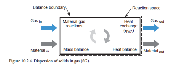
Dispersion of solids in gas. In this case a stream of solids of any composition is dispersed in a gas stream (abbreviation SG, Figure 10.2.4). Depending on the particular temperatures, heat exchange occurs in conjunction with the corresponding reactions (see above). If the heat exchange is complete, then there is no difference in temperature between the emerging gas stream and the emerging stream of solids. In this situation the maximum heat has been exchanged between the two streams.
Practically complete heat exchange between gas and material was assumed by Vosteen (1971) on the basis of theoretical considerations for cyclones in preheaters for the clinker burning process, provided it was not necessary to cover the heat requirement for a reaction. It was also supposed that the kiln feed is completely dispersed in the gas. However, the two assumptions are not entirely valid. Complete dispersion can certainly be assumed for those gas and dust flows which leave the cyclone in the direction of the next highest stage. However, this is not necessarily the case for the fraction of kiln feed which has been separated.
It is necessary to check whether sufficient time is available for these reactions to take place. In the model this is assumed for all reactions in the gas phase, for the conversion of organic constituents in the kiln meal, and for condensation and evaporation of water. However, this assumption is not immediately justifiable for the calcination reactions as the time required for calcination at a temperature of, say, 800°C to 950°C, can be 1 to 100 sec depending on the particle size of 10µm to 100µm (Reh, 1983). The residence time in a cyclone is therefore not sufficient under some circum-stances for completion of the reaction in the larger particles.
This is taken into account in the model with the aid of an efficiency for the heat exchange (ηWA). It is dependent both on the available reaction time and on the extent to which calcination is involved in the overall reaction. The efficiency ηWA is lowest, and can drop to about 65%, for the extreme case where the heat exchange between gas and kiln feed is used entirely for calcination for which little time is available.
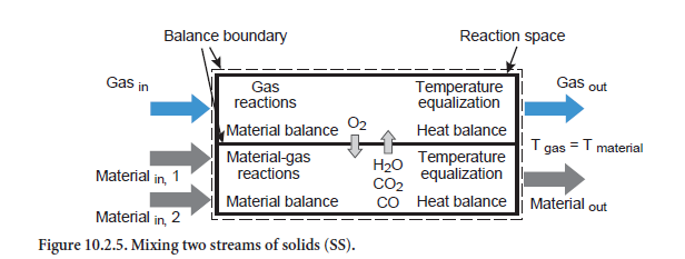
Mixing two streams of solids. The composition of a total stream mixed from two individual streams of solids is obtained initially from a mix calculation (abbreviation SS, Figure 10.2.5). If, however, there is a temperature difference between the two input streams, then heat exchange occurs as well. This can be associated with chemical and physical reactions in which the gas phase is also involved. In addition, there is a corresponding change to the composition of the emerging total stream of solids. Comparable with the unit operation for heating/cooling of a stream of solids, it is also assumed in this situation that the gas and solids leave the balance area with the same temperature.
Heating/cooling a gas stream. This unit operation is used to calculate the heat exchange between a gas stream and its surroundings (abbreviation HG, Figure 10.2.6). Reactions can also occur if CO and/or H2 is present together with O2 and a minimum temperature is exceeded. The level of conversion is governed by the temperature reached in the reaction space. The conversion is complete if an upper limiting temperature is exceeded. In the temperature range between the minimum temperature and the limiting temperature, the conversion is proportional to the temperature change.
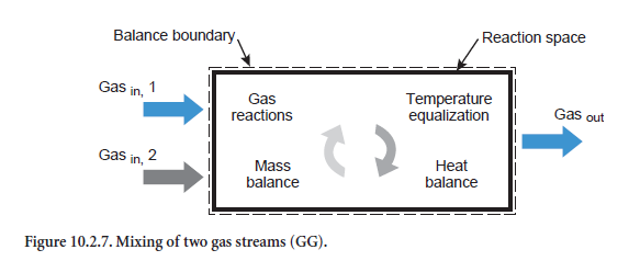
Mixing two gas streams. When two gases are mixed (Figure 10.2.7) a gas is produced with a corresponding mixed composition (abbreviation GG). Respective gas phase reactions can also occur, as with the heating/cooling of a gas stream, HG (see above). It is assumed that the emerging gas not only has a homogeneous composition but a completely uniform temperature as well.
Cyclone Preheater
In the calculations, the preheater is subdivided into single cyclone stages, and the mixing of gas and kiln feed is determined in each stage. The kiln feed is fed into the riser duct of a stage and is heated in the flow. It is separated from the gas in the cyclone in accordance with the dust collection efficiency (ηA) and deposited in the stage below. Heat is exchanged between the two flows through the intensive mixing of kiln feed and gas. The procedure is repeated in each stage, always at a higher temperature, during which the kiln feed is partially calcined.
The calculations for a single cyclone stage are based on the unit operations explained above. On entering the cyclone stage (Figure 10.2.8), the gas from the previous stage mixes with false air and is correspondingly cooled (mixing of two gas streams, GG). The kiln feed (dust) entrained in thegas mixes in a comparable way with the kiln feed collected from the next higher stage (mixing of two streams of solids, SS). The heat loss through the cyclone wall is then calculated with an expres-sion which includes the thickness of the brickwork and the surface area of the cyclone. The heat loss is taken into account in the gas stream which is correspondingly cooled (heating/cooling a gas stream, HG).
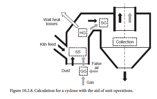
The most important step from the heat engineering aspect is the subsequent mixing of dust and gas (dispersion of solids in gas, SG). Complete temperature equalization between dust and gas is not assumed in principle in the calculations. This would correspond to the maximum heat exchange. The effectiveness of heat exchange, which is referred to below as thermal efficiency (ηWA), depends on the design of the cyclone and as a rule is unknown. The thermal efficiency could be determined in a specific instance with the aid of operational measurements and an energy balance for the individual cyclone. However, such measurements are complicated and at present are not feasible in the lower stages of a preheater from the aspect of measurement technology. Calculations based on flow models would also be possible but require detailed understanding both of the energy exchange between gas and dust and also of the dust collection efficiency.
The last step in the calculations for a single cyclone stage consists of dividing the dust stream in accordance with the dust collection efficiency (ηA). The fraction which has been collected leaves the cyclone and passes to the stage below, while the dust which had not been collected is trans-ported to the stage above together with the gas. Like the thermal efficiency ηWA, the dust collection efficiency (ηA) is dependent on the design of the cyclone. However, unlike the thermal efficiency, the dust collection efficiency is defined in the model. Relevant data are available, especially for the upper stages, as measurements there are less complicated than in the lower stages.
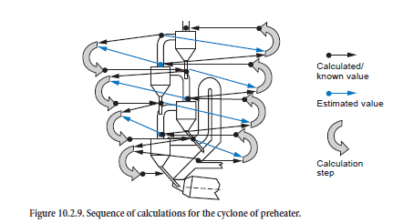
The calculations for the individual cyclones must be combined with one another for the complete calculation for the preheater during which the streams of kiln feed, dust, and gas are linked with one another. The situation in each stage is determined in succession starting from the top cyclone; the calculation therefore initially follows the direction of the kiln feed flow (Figure 10.2.9, left-hand side). This condition of the kiln feed entering a stage is therefore given directly from the calculation for the stage above (black arrows). On the other hand, the condition of the gas-dust mixture entering a stage is initially unknown and must be estimated (red arrows).
When the calculation for a preheater based on the estimated values for gas and dust has reached the bottom stage, the sequence of the calculation is reversed in the direction of the gas flow (Figure 10.2.9, right-hand side). This enables the estimated values to be improved as the condition of the gas and dust stream entering a stage is given directly from the calculation for the stage below (black arrows). Now, however, the condition of the incoming kiln feed is unknown and is taken from the previous calculation (gray arrows).
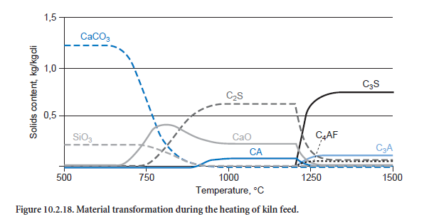
The calculations are repeated until the energy and mass balances both for the individual cyclones and for the entire preheater are fulfilled with sufficient accuracy. For cyclones, the maximum permissible balance error is 1 W or 10 g/h and for the entire preheater, it is 50 W or 50 g/h.
Calciner
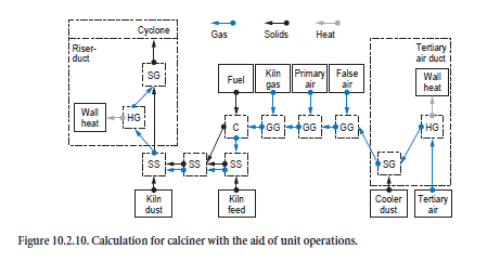
The process taking place in the calciner proceeds on the basis of the mixing of tertiary air, kiln inlet gas, and combustion gases from the firing system with the appropriate streams of dust and kiln feeds. Figure 10.2.10 shows how the unit operations are linked to one another.
The first step is to calculate the processes taking place in the tertiary air duct. Gas and dust from the cooler which pass through it to the calciner are cooled in accordance with the wall heat losses in the duct (heating/cooling of gases, HG). Complete temperature equalization is assumed between gas and dust (dispersion of solids in gas, SG).
The mixing of the tertiary air with false air, primary air, and kiln gas (mixing of gases, GG) is calculated in the next step before the combustion calculation (C). The composition of the resulting combustion gas and ash depends on the gas and fuel composition. The tertiary air dust mixes with the kiln feed from the preheater and is heated by the combustion gases (mixing of two streams of solids, SS). The mixing with the ash from the combustion and with the kiln dust is then taken into account (mixing of two streams of solids, SS). Complete temperature equalization between gas and dust (dispersion of solids in gas, SG) is assumed for the calculation of the processes taking place in the calciner riser duct. The wall heat losses are taken into account here at the same time (heating/cooling of gases, HG). The gas-dust mixture leaving the calciner riser duct enters a cyclone, and the dust is collected from the gas in accordance with the collecting efficiency. The calculation for the processes taking place within the calciner cyclone follows the same procedure already described above. Gases and dust from the calciner leave in the direction of the preheater, while the material collected in the cyclone passes to the kiln inlet.
In some plants a small fraction of the gas stream is drawn off to limit recirculating chlorine and/or sulfur systems between the kiln and preheater/calciner. This is cooled with air to condense chlorine and sulfur on the dust particles. This process is catered for in the model by branches in the gas and dust streams at the kiln inlet. The gas and dust which have been drawn off are then mixed theoretically with the ambient air.
Rotary Kiln
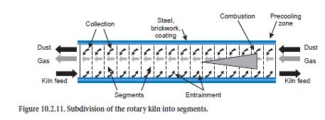
For calculating the steady-state operating condition, the rotary kiln is subdivided theoretically along the axis into segments (about 20 to 50, Figure 10.2.11) for which the material and heat balances are solved. Gas, dust, and fuel enter each segment from the adjacent segments in the appropriate direction of flow and react with one another. Exchanges of energy (e.g., through radiation and convection) and mass (e.g., through calcination) occur, and the combustion of the fuels and the heat losses as a result of thermal conduction through coating, brickwork, and steel shell are taken into account. Entrainment of kiln feed by the kiln gas, as well as the collection of the dust from the kiln gas in the bed of kiln feed, sometimes leads to mixing of the two streams of material and this may also be associated with reactions.
Flame shape and burn-out characteristics differ depending on the fuel, and affect the temperature and concentration profiles of the combustion gases along the kiln axis. This is taken into account in the model by mathematical allocation of the total quantity of fuel to the relevant segments. Combustion gases and heat are liberated accordingly in segments along the kiln axis. To a first approximation this makes it possible to investigate the use of fuels with different burn-out charac-teristics and different compositions.
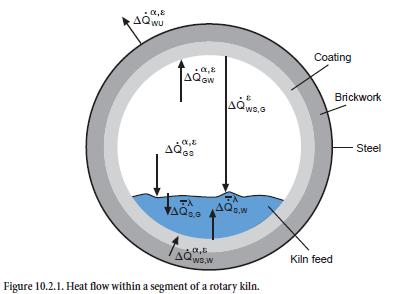
Heat exchange. The heat transfer by radiation, convection, and thermal conduction is calculated with the mathematical expressions normally used in heat technology. Within a segment, the model largely follows the approach used by Frisch (1983). There is both direct and indirect exchange of heat between kiln feed and gas (see Figure 10.2.1 already shown). The direct exchange at the surface of the kiln feed is made up of a convection and a radiation component (∆Q• GSα,ε), and the indirect heat exchange involves the wall which is also heated by the combustion gases by convection and radiation (∆Q• GWα,ε) and gives back part of this heat to the kiln feed. Both the upper side and the underside of the kiln feed are involved in this process; the heat at the upper side of the kiln feed is exchanged exclusively by radiation (∆Q• WS,Gε) but at the underside, part of the heat is also transferred by convection (∆Q• WS,Wα,ε). Heat transport within the kiln feed (∆ S,Gλ, ∆Q• S,Wλ) requires a temperature gradient to overcome the thermal resistance. Heat losses to the surround-ings (∆Q• WUα,ε) arise as a result of thermal conduction through coating, brickwork, and steel shell and are calculated in accordance with the equations given by Gardeik (1985).
The heat flows which are taken into account within a segment can therefore be summarized as follows:
• Heat exchange between gas and kiln feed (radiation ∆Q• GSε and convection ∆Q• GSα)
• Heat exchange between gas and kiln wall or coating (radiation ∆Q• GWε and convection ∆ •QGWα)
• Heat exchange between kiln wall and kiln feed at the upper side of the kiln feed (radiation ∆ •QWS,Gε)
• Heat exchange between kiln wall and kiln feed underside of the kiln feed (radiation ∆Q• WS,Wε and convection ∆Q• WS,Wα)
• Heat flow from the outside of the kiln feed to the inside of the kiln feed (thermal conduction ∆Q• S,Gλ and ∆Q• S,Wλ)
• Heat loss at the outside of the shell (radiation and convection ∆Q• WUε and convection •QWUα)
According to these models, the total heat ∆QBG flowing into the kiln feed within a segment is therefore made up of five heat flows, of which two are transferred directly from the gas (∆ •QGSα, ∆ •QGSε) and the other three are transferred indirectly via the kiln wall (∆ •QWS,Wα, ∆ •QWS,Wε,∆ •QWS,Gε) The chemical, physical, and mineralogical changes in the kiln feed are essentially deter-mined by this overall heat exchange.
The overall heat exchange of the gas ∆ •QGas with its surroundings can also be considered in the same way. It consists of the convection and radiation components both in the exchange with the kiln feed (∆ •QGSα, ∆ •QGSε) and with the kiln wall (∆ •QGWα, ∆ •QGWε) and, together with the gas reac-tions, affects the temperature change of the gas as it flows through the segment.
Material-flows. The mass balance for a segment is characterized essentially by the incoming and outgoing mass flows of the feed and gas. Mass transfer between the material-flows can occur within a segment through reactions. In particular, this includes the calcination of the limestone during which the CO2 contained in the CaCO3 is transferred to the kiln gas. Dust flows are also taken into account in the model as dust is carried from the cooler into the kiln with the secondary air. It mixes with the fuel ash and, depending on the gas velocity, is transported through the entire kiln to the preheater or calciner, or is deposited on the kiln feed. Kiln feed can also be carried away from the material bed by the kiln gas if it is entrained as a consequence of the rotational movement of the kiln and mixes with the dust in the kiln gas.
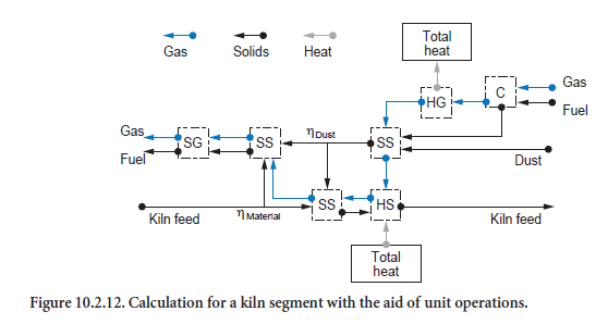
Calculation procedure. During the calculations, repeated use is made of the unit operations (Figure 10.2.12). The mixing of kiln feed and dust is determined by two parameters. ηdust describes the dust collection in the kiln and ηmaterial describes the entrainment of the kiln feed. The part of the kiln feed which has been entrained mixes with the dust in the gas phase (mixing two streams of solids, SS) and leaves the segment under consideration after complete temperature equalization with the gas (dispersion of solids in gas, SG). The majority of the kiln feed, however, mixes with the collected dust (mixing two streams of solids, SS), is heated (heating/cooling of solids, HS), and then leaves the segment. Incoming gas is possibly first heated by the combustion of fuels (combus-tion calculation, C) before heat exchange with the surroundings takes place. The ash produced during the combustion mixes with the dust entrained in the gas (mixing two streams of solids, SS).
Calculations running in opposing directions along the kiln axis have to be repeated many times (approximately 30 to 80 times) before the results are matched sufficiently accurately to one another. The requirement for this calculation is comparatively high; overall it is usually necessary to carry out the calculations listed in Figure 10.2.12 approximately 10,000 to 100,000 times before the calculated solution for the entire kiln is in numerical equilibrium. It must be borne in mind that each of these calculations is associated with the solutions (also iterative) of the balance equa-tions for several unit operations.
Grate Cooler
The calculations are based on empirically determined heat transfer laws for forced convection in particulate packed beds through which a flow is passing and which consists of individual particles (VDI, 1994). They were determined by extensive test series and describe the heat transfer between clinker (particles) and cooling air (fluid) by functions with characteristic Nusselt, Reynolds, and Péclet numbers. Among other things, the equations take account of the material properties of the cooling air and particles, the size and shape of the particles, the volume of voids in the particulate bed, and the nature of the approach flow to the particles. An equation can only be utilized in appli-cations which are covered by the test program. This can be checked using the validity ranges speci-fied for the characteristic numbers.
The heat flow at the contact surface between cooling air and clinker grain can be calculated with the aid of the heat transfer coefficient. The actual heat transferred depends on whether sufficient heat can be transported from the inside of the clinker grain to its surface. This process depends essentially on the material properties and on the duration of the cooling. Corresponding equations for unsteady-state heat conduction can also be taken from the literature (VDI, 1994) and make it possible to determine the requisite quantity of heat. Here again it is assumed as a simplification that the clinker particles are spherical.
Melt phase and radiation. In accordance with the definition of the model, the clinker at temper-atures above 1280°C contains clinker melt which is formed in the sintering zone of the kiln through the input of heat. During the crystallization of the melt in the precooling zone of the kiln and in the cooler, this heat of fusion is liberated again and contributes to heating the secondary and tertiary air. The model equations take account of this heat input in the energy balance of the cooler in accordance with the assumptions presented above. On the other hand, the influence of the melt phase on the heat transfer in the particulate bed and on the unsteady-state heat conduc-tion in the clinker particles is ignored. In addition to the forced convection there is also an exchange of radiant heat between the top layer of clinker and the roof and walls of the cooler. As a result of thermal conduction the radiant heat is dissipated through the brickwork and steel hous-ing and contributes to the heat loss from the clinker.
Particulate dust. Clinker from the rotary kiln enters the grate cooler and is transported toward the cooler outlet by the grate movement. During this process the friction between the particles produces dust which is entrained and carried away by the cooling air. Depending on where the dust is formed it can leave the cooler in various ways. For example, it can be transported away with the secondary air toward the kiln, with the tertiary air toward the calciner firing system, or with the cooler exhaust air toward the cooler dedusting system. In the calculations it is assumed that the dust is entrained uniformly on the entire length of the cooler. The total quantity depends on the dust levels chosen for the secondary air, tertiary air, and cooler exhaust air. These, together with the quantity of cooling air, are used to calculate the clinker mass flow carried out by the dust.
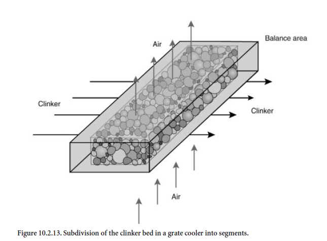
Subdivision of the cooler into balance segments. For calculation purposes the length and height of the clinker bed in the grate cooler are subdivided into individual balance segments which cover the entire width of the cooler. The results presented were calculated for a cooler in which the length was divided into 45 segments and the height into 6 segments. The dimensions of a segment are about 0.5 m in length, 0.1 m in height and 3.0 m in width. As is shown schematically in Figure10.2.13, the clinker flows horizontally and the cooling air flows vertically through each balance segment. The balance segments are filled with spherical clinker of varying particle size for which a size distribution is specified. In practice it is dependent on material and on process engineering conditions which are not included in the framework of the model. The calculations described here differentiate between fine, medium, and coarse clinker (Figure 10.2.14).
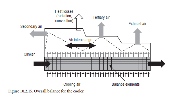
Above the clinker bed the cooling air combines to form secondary, tertiary, and exhaust air in accordance with the guidelines (Figure 10.2.15). In practice the proportions of secondary, tertiary, and cooler exhaust air in the total quantity of cooling air used are dependent on several factors. These include, for example, the settings of the cooling air fans, the firing systems in the kiln and calciner, and the flow resistances in the kiln and tertiary air duct. To some extent they concern questions of gas flow which are not covered by the model. The proportions in which the total quantity of incoming air is divided into secondary, tertiary, and cooler exhaust air must therefore be specified for the calculations.
The calculations start with the assumption that the secondary air comes exclusively from the front section of the cooler and that the off-take for the tertiary air is adjacent to this. The remaining air is removed as cooler exhaust air. The secondary air reaches its highest temperature under these conditions. As a rule, however, there is an interchange between secondary and tertiary air so that their temperatures approach one another to a greater or lesser extent depending on the mixing. In practice the degree of mixing depends mainly on the structural shape of the cooler, so it cannot be calculated from the model but is specified with the aid of a parameter.
Overall Plant Operation
The model for the complete plant is based on the models of the plant sections. Steady-state operat-ing conditions of preheater, calciner, kiln, and cooler are each determined in steps using iterative calculation procedures; the initially estimated solutions of the balance equations for mass and energy are improved with the aid of similar calculation steps until the required accuracy is achieved.
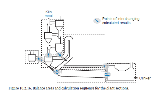
On top of this, the calculation of the steady-state condition for the complete plant combines these solution steps and exchanges the results for the steady-state operating conditions of preheater, calciner, bypass, kiln, and cooler at their interfaces (Figure 10.2.16). At the beginning an estimate is made of the condition of the gas and kiln feed at these interfaces. These include the gas outlet from the bottom cyclone, the kiln inlet with gas off-take, the cooler inlet, and the tertiary air duct. On this basis the iteration starts with the calculations for the preheater. One of the results which is used further is the condition of the kiln feed before entry into the riser duct of the calciner, which is included in the calculations for the calciner. This calculation step then gives the condition of the kiln feed at the kiln inlet. This is followed by the kiln calculation, the results of which determine the condition of the clinker entering the cooler. The results of a cooler calculation supply not only the outlet condition of the clinker but also the temperature and composition of the secondary and tertiary air as well as of the dust contained in them. The calculations for the bypass complete one iteration step and the calculations are then continued with a fresh calculation for the preheater.
Within one iteration step for the complete plant the results for the plant sections are exchanged between the sections. For example, after a kiln calculation, new results are available for the clinker at the cooler inlet and for the kiln gas and dust at the kiln inlet. These are used immediately in the calculations for the cooler and calciner. The results are also passed on in a similar way to the other plant sections so that there is a progressive change in the input variables for the model. However, during the calculation these changes become ever smaller until after a certain time the results reach a steady state condition.
For the results presented here the calculation ends as soon as all the model sections and the complete model fulfill the requirements for the accuracy of the balances listed in Table 10.2.6 and the temperature profile of the kiln has not changed at any point by more than 2 K in 10 successive iteration steps. As a rule this is the case after 30 to 80 steps and requires about 20 minutes in a normal commercial PC (Pentium III, 800 MHz, Windows NT). The calculations have shown that lower demands on the accuracy for the unit operations can lead to numerical problems when solving the balances for the plant components which are based on them.
RESULTS AND DATA ANALYSIS
Heating the Kiln Feed
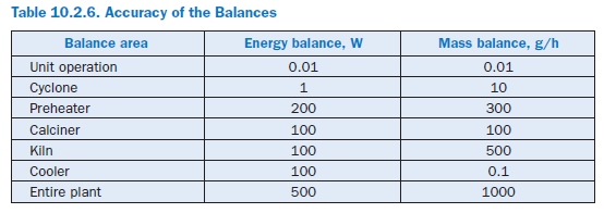
The heat requirement based on the above-mentioned model assumptions for heating kiln feed of normal composition is illustrated in Figure 10.2.17 with the aid of two heating curves. The first curve only describes the heats of reaction, i.e. those quantities of heat which are converted as a result of chemical reactions of the kiln feed. The second curve describes the total energy require-ment, i.e. that heat which in total is needed to reach the corresponding temperature.
Exothermic reactions lead to a drop in the curve for the heats of reaction (black) and endothermic reactions lead to a rise. For the kiln feed on which these curves are based there is a theoretical heat energy requirement for the clinker burning process of a total of 1540 kJ/kgcli. This is about 100 to 200 kJ/kgcli lower than is usually given as in the present case the combustion of organic constituents in the kiln feed already covers part of the heat requirement. This can be seen in the curve for the heats of reaction from the drop in the temperature range between 450°C and 750°C. On the other hand the total heat converted is higher; it comes to 3456 kJ/kgcli for a final temperature of 1450°C.
The strongly endothermic calcination reaction is conspicuous in the temperature range above about 650°C. It starts as low as 550°C and is completed at about 960°C. Between 600°C and 1300°C it overlaps with the reaction of clinker phase formation, to which the exothermic reaction of β-C2S formation makes a particularly significant contribution. Liquid phase formation begins when the temperature exceeds 1280°C. The phase transition of the kiln feed from solid to liquid requires heat which leads to a further rise in the heat requirement.
One of the differences between the heat of reaction and the total heat is that heat is needed for rais-ing the temperature of the reaction products – gases and solids. This heat can be recovered to some extent in the clinker burning process as the clinker does not leave the process at, for example, a tem-perature of 1450°C. The heat produced during its cooling is available for heating the kiln feed and offsetting heat losses, and makes a corresponding reduction in the total heat energy requirement.
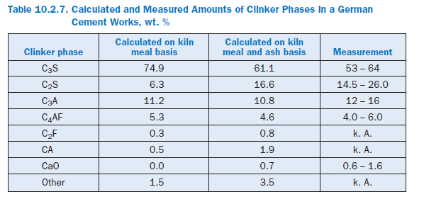
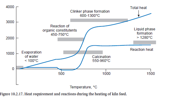
Figure 10.2.18 shows how the kiln feed composition changes as it is heated. Calcination proceeds with increasing strength at about 650°C; there is a corresponding decrease in the CaCO3 concen-tration while at the same time CaO is formed. However, the increase in CaO is diminished by the formation of C2S, as CaO and SiO2 are consumed in this reaction. The clinker phases CA and C2F (not shown) are also produced at even higher temperatures, above about 800°C. Above 1200°C they are converted into C3A and C4AF, while C2S is converted into C3S. CaO also takes part in these reactions.
The calculated percentages of the clinker phases are listed in Table 10.2.7. The results shown in Figure 10.2.18 and the second column of Table 10.2.7 are based on a calculation which was carried out with the kiln meal from a German cement works. The ash fractions from the fuel are therefore not included in the calculation. The results show comparatively high levels of C3S and low levels of C2S. The figures in the third column, however, come from a calculation for the entire plant in which the ash introduced into the kiln and calciner mixes locally with the hot meal. Its SiO2 content leads to lower levels of C3S and higher levels of C2S in the clinker. The results agree well with typical figures for the works.
The Complete Plant
The calculations were performed for the four-stage preheater plant shown in Figure 10.2.16, for which an energy balances is available. All the data on the marginal conditions for the process were taken from the test report as long as appropriate measurements had been carried out. This included, for example, the information on the input materials and all the adjustments undertaken by the operating personnel. Parameters which were not available were estimated on the basis of literature information and empirical values from operational measurements.
Based on such a reference condition it is possible to apply changes to the model in order to investi-gate the overall results. For this, the results of the reference condition are compared to those which were obtained under changed conditions. It must be borne in mind that clinker with a quality comparable with that of the reference condition must still be produced under the changed condi-tions. This was ensured by assuming in the calculations that the same kiln feed temperature as in the reference conditions must still be achieved in the sintering zone under the changed conditions. In the studies this temperature was therefore adjusted to match the temperature in the reference condition with the aid of the fuel feed to the primary firing system. The additional use or saving of fuel therefore permits an initial estimate to be made of the effects of the parameter change on the energy in the complete process.
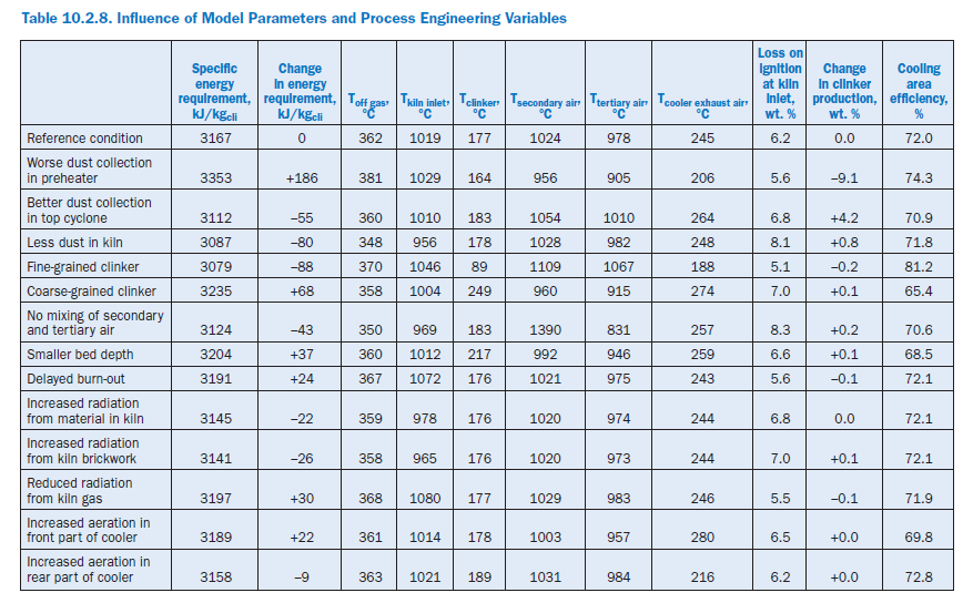
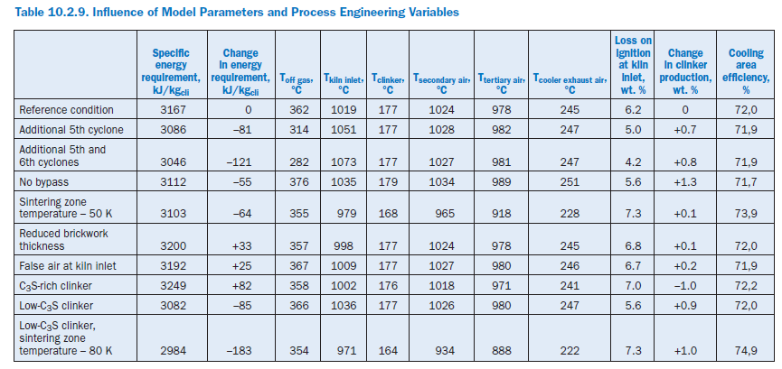
The following calculation studies on the complete model refer not only to the effect of model parameters and process engineering variables (Table 10.2.8) but also to changes in the complete plant and material criteria (Table 10.2.9). In each case an individual parameter was changed and at the same time the kiln feed temperature in the sintering zone was adjusted to match the reference condition with the aid of the fuel feed to the primary firing system.
Additional correction measures – particularly optimization of the operating condition – were dispensed with so as not to mask the effects of the parameter change. The calculations presented here should therefore not be evaluated as being the result of plant optimization to achieve the lowest possible specific energy requirement. This requires further calculations in which specific changes are also made to other settings. In addition, practical implementation would have to be checked in each individual case in order to avoid plant stoppages or damage.
Dust collection in preheater. The changes in the recirculating dust systems in the preheater have a comparatively significant effect on the specific energy consumption of the plant. A deterio-ration in the collecting efficiency of the two top cyclones by 5% in each case to 90% and 85%, respectively, and in the third cyclone by 10% to 60% lead to an additional consumption of 186 kJ/kgcli (+5.9%). A substantial proportion of this is accounted for by the losses with the off gas (103 kJ/kgcli) and the off gas dust (58 kJ/kgcli). The slightly increased wall heat losses contrast with somewhat lower losses through cooler exhaust air and clinker.
Increased dust losses reduce the clinker production by 9.1% and in this way also affect the temper-ature profile in the plant. The cooling air in the cooler is distributed to a smaller mass of clinker so that this is cooled to a greater extent. At the same time there is a drop in the temperatures of the secondary and tertiary air and in the temperature in the sintering zone (-44 K). This results in a deterioration of the heat transfer from the gas to the kiln feed, and the gas temperature at the kiln inlet rises by 10 K. Increased recirculating dust systems lead to the establishment of higher temper-atures than in the reference condition, especially in the upper part of the preheater.
Similarly, an improvement in the collection efficiency of the top cyclone from 95% to 98% with otherwise unchanged collection efficiencies produces saving of 55 kJ/kgcli (-1.7%) and an increase of 4.2% in the clinker production.
Dust generation in rotary kiln. In the reference condition the dust concentration in the kiln gas rises along the kiln axis from 0.112 kg/m3stp, dry (0.036 kg/kgcli) in the incoming secondary air to 1.38 kg/m3stp, dry (0.564 kg/kgcli) at the kiln inlet. During the parameter studies a lower dust gener-ation was assumed so that the dust content of the gas at the kiln inlet rose to only 0.654 kg/m3stp, dry (0.268 kg/kgcli). This led not only to a reduction of 27% in the exchange of kiln feed and kiln feed dust between kiln and preheater but also of a reduction of 80 kJ/kgcli (2.5%) in the specific energy consumption, with an increase of 0.8% in clinker output.
Half the saving is due to the off gas which leaves the preheater at 348°C instead of 362°C. Lower bypass losses and reduced wall heat losses account for further savings of about 10 kJ/kgcli each.
The changed recirculating dust systems lead to a displacement of the material flows and therefore also of the temperature profile. The smaller quantity of dust means that less heat is carried from the kiln into the preheater and calciner so that there is a general decrease in the temperatures there. In the kiln the kiln feed is heated more rapidly than in the reference condition as the heat from the firing system is distributed to a smaller quantity of kiln feed. This increases the gas temperature in the sintering zone, which assists the heat transfer from gas to kiln feed. As a result the gas temperature at the kiln inlet drops to 956°C, which is 63 K lower than in the reference condition, while the temperature in the cooler remains virtually unchanged.
Particle size distribution of clinker. Fine-grained clinker is easier to cool than coarse-grained clinker. The assumptions made here about the particle size distribution (Figure 10.2.14) have signifi-cant effect on the efficiency of the cooling area; for fine-grained clinker the calculation gives an unrealistically high value (81.2%). The change in the particle size distribution has a direct influence on the specific energy consumption of the plant. In the case of fine-grained clinker, it gives a saving of 88 kJ/kgcli (2.8%) and for coarse-grained clinker results in an additional consumption of 68 kJ/kgcli (2.2%). In both cases this is primarily attributable to changed energy losses through the clinker and cooler exhaust air. At the same time the temperature profile of the kiln, preheater, and calciner is raised for fine-grained clinker and lowered for coarse-grained clinker.
Mixing of secondary and tertiary air in cooler. The temperatures of the secondary and terti-ary air depend on the mixing of the air within the cooler, which can be specified in the model with the aid of a parameter. Without any mixing the strongly heated air from the first few segments passes exclusively into the secondary air and the less strongly heated air from the following segments passes into the tertiary air. In the case of complete mixing the two air flows leave the cooler at the same temperature.
Full theoretical separation of the two air streams leads to an energy saving of 43 kJ/kgcli. The majority of this is due to savings in the off gas (32 kJ/kgcli). The wall heat losses are also reduced by 18 kJ/kgcli, and the losses due to the exhaust air temperature from the cooler, which is 12 K higher, are increased by 11 kJ/kgcli.Under these theoretical preconditions the secondary air reaches an unrealistically high temperature of 1390°C. This has the effect of increasing the gas temperature in the sintering zone of the kiln by 28 K to 1928°C. Because of the resulting improved heat transfer from gas to kiln feed the gas temperature at the kiln inlet falls to 969°C, which is 50 K lower than in the reference condition. This difference is reduced in the direction of the gas flow, and the raw gas leaves the preheater with a temperature which is 12°K lower than in the reference condition.
Depth of clinker bed in cooler. By increasing transport speed of the clinker in the cooler, the depth of the clinker bed was reduced from 63 cm to 50 cm. This shortens the path of the air through the clinker and reduces the contact zone between cooling air and clinker. There is a corre-sponding deterioration in the heat transfer, and the efficiency of the cooling area decreases to 68.5%, which is 3.5% lower than in the reference condition. The additional heat losses from the cooler increase the specific energy requirement by 37 kJ/kgcli (1.2%), and the temperatures of the secondary and tertiary air each fall by about 30°K.In contrast, the temperature of the clinker at the cooler outlet rises by 40°K to 217°C and the temperature of the cooler exhaust air rises by 14°K to 259°C. Temperature distribution and flows of kiln feed in the other parts of the plant change only very slightly.
Burn-out behavior of fuel in kiln firing system. In the reference case it is assumed that the coal fed into the primary firing system is completely burnt in the first 15 m of the flame and that there is a linear decrease in the quantity of fuel converted. These preconditions produce a linear depend-ence of the amount of heat liberated on the flame length. An extension of this burn-out distance by 50% to 22.5 m leads to an additional heat requirement of 24 kJ/kgcli (0.7%) caused by displacement of the temperature profile toward the preheater. This raises the temperature of the gas at the kiln inlet by 32°K and in the off gas by 5°K, and leads to higher raw gas and bypass gas losses.
Radiation properties of brickwork, kiln feed, and gas. The radiation properties of a material are described by the emissivities of the brickwork, kiln feed, and gas. The parameters can adopt values between 0.0 and 1.0, in which high numerical values signify a good radiation heat exchange between the medium in question and its surroundings. In three independent calculations the emis-sivities of the brickwork, kiln feed, and gas in the kiln were each changed by 0.3. The effects on the specific energy requirement amounted to 0.7% to 1.0% and can be attributed entirely to the temperature changes of off gas and bypass gas.
Raising the emissivity of the kiln feed in the kiln from 0.6 in the reference condition to 0.9 theoret-ically assists its heat exchange with the surroundings. There is an improvement in the heat transfer from the kiln gases to the kiln feed in the kiln and the specific energy requirement is reduced by 22 kJ/kgcli (0.7%). Compared with the reference condition the gas temperatures fall by 23°K near the firing system and by 41°K at the kiln inlet. However, this temperature difference from the refer-ence condition is reduced in the preheater and calciner and is only 3°K in the off gas. The effects on the processes in the cooler are slight as the clinker leaves the kiln at practically the same temperature as in the reference condition.
Raising the emissivity of the brickwork from 0.5 to 0.8 leads to comparable results, with an energy saving of 26 kJ/kgcli (0.8%). In this case only the kiln wall has a major involvement in the increased heat flow from the kiln gas to the kiln feed. Theoretically, a reduction in the emissivity of the kiln gas from 0.8 to 0.5 leads to worse heat transfer in the kiln. The temperature of the gas at the kiln inlet rises by 37°K to 1056°C, and higher gas temperatures (+26°K) are also reached in the sintering zone.
Distribution of cooling air in cooler. In the reference condition all three grates of equal size in the cooler are uniformly aerated. Two independent calculations were carried out to investigate the influence of increased aeration of the front grate and of the rear grate, respectively, with a constant total quantity of cooling air. During aeration of the rear grate with 50% of the cooling air, the temperatures of the secondary and tertiary air are increased while the temperature of the cooler exhaust air falls. The overall effect is slight and leads to an improvement of only 9 kJ/kgcli in the specific energy requirement. Increased cooling in the front part of the cooler, however, raises the specific energy requirement by 22 kJ/kgcli.
Additional cyclone stages. The heat exchange between gas and kiln feed can be improved through additional cyclone stages in the preheater. Theoretically, a new fifth stage reduces the specific energy requirement of the plant by 8 kJ/kgcli (2.6%) and a sixth stage produces a total saving compared with the reference condition of 121 kJ/kgcli (3.8%). In both cases this is attributa-ble entirely to the reduced heat losses through off gas and off gas dust, the temperatures of which are reduced by 48°K in the case of the five-stage preheater and by 80°K in the case of the six-stage preheater. At the same time the temperature level at the kiln inlet also rises as a result of the more intensive heat exchange in the preheater, and there is a corresponding drop in the loss on ignition of the kiln feed. The increase in clinker production by 0.7% and 0.8% respectively can be attrib-uted to the increased total dust collection by the preheater, as it is assumed in all cases that the collection efficiency of the top cyclone is 95%.
Operation without bypass. The gas off-take at the kiln inlet of 3.5% relative to the gas volumetric flow is omitted during the operation without bypass. This results in savings in the gas and dust of 92 kJ/kgcli and 7 kJ/kgcli,respectively. At the same time the kiln throughput is increased by 1.3% because of the lower dust losses. The greater quantity of clinker in the cooler causes the temperatures of the secondary and tertiary air to rise by about 10°K and also contributes to the fact that the gas tempera-ture at the kiln inlet is 16°K higher than in the reference condition. The higher temperature level is maintained as the gas passes through the preheater and leads to higher off gas losses (+51 kJ/kgcli) than in the reference condition. There is an overall heat gain of 55 kJ/kgcli (1.7%).
Lowering the sintering zone temperature. As a rule the sintering zone temperature cannot be lowered without also changing the nature of the clinker. However, under certain conditions it is possible, by using fluxing agents and/or mineralizers, to keep these changes within justifiable limits. In the present case it was assumed that such measures allow the sintering zone temperature to be reduced by 50°K. This results in an overall fuel saving of 64 kJ/kgcli (2%). This is attributable primarily to lower losses in the off gas and cooler exhaust air. However, there is also a reduction in the total wall heat losses by 14 kJ/kgcli as well as in the heat losses through the clinker.
Wall thickness of brickwork. As part of the calculations the thicknesses of the brickwork for the kiln, calciner, tertiary air duct, and cyclones were each reduced by 50 mm. This increased the wall heat losses from 323 kJ/kgcli to 374 kJ/kgcli.In conjunction with the lower off gas losses this resulted in total in an increase in the specific energy requirement by 33 kJ/kgcli (1.1%).
False air at kiln inlet. False air at the kiln inlet can be caused by, for example, a defective kiln inlet seal. Additional air ingress of 0.052 m3stp, dry/h was assumed for the calculations so that the O2 concentration at this point rose from 4.9% to 6.2%, and the kiln feed was cooled. To compen-sate for this the heat input had to be raised by 25 kJ/kgcli (0.80%) in order to maintain the sinter-ing zone temperature. The losses occur primarily in the off gas, leaving the preheater at a temperature which is 5°K higher than in the reference condition.
Clinker quality. Material influencing factors were investigated by assuming differing levels of lime in the kiln meal. In the reference condition, the lime standard of the mixture of kiln meal and fuel Table 10.2.10. Calculated Clinker Phases, wt. %ash was 93.6. This mixture was changed in two calculations so that the lime standards were 100.0 and 86.0, respectively, for the same silica ratio, alumina ratio, and silicic acid modulus.
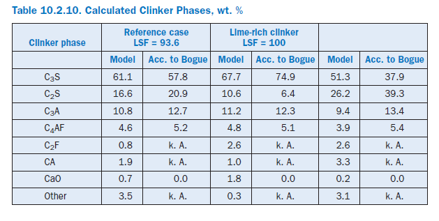
Burning the lime-rich clinker theoretically increases the specific energy requirement by 82 kJ/kgcli as a result of the chemical reactions. This is due primarily to the additional energy for calcining the CaCO3,which is partially offset by the heat recovery during the clinker phase formation. Unlike Bogue (1929) calculation, the model also takes into account the formation of intermediate phases which are not present in the burnt clinker (Table 10.2.2). The percentage of C3S increases from 61.1% to 67.7% (Table 10.2.10) at the expense of the percentage of C2S, which decreases from 16.6% to 10.6%. At the same time, the clinker production is reduced by 1.0%. The use of the low-lime kiln feed mix has the opposite effect. With a LSF (Lime Saturation Factor) of 86 the specific energy requirement falls by 85 kJ/kgcli compared with the reference condition and leads to a C3S content of only 51.3%. At the same time, the clinker production rises by 0.9%.
In practice the change in LSF is generally linked with a change in process temperatures. With the simultaneous assumption of a low-lime kiln feed mix and a sintering zone temperature which is reduced by 80°K, there is theoretically a reduction in the specific energy requirement by183 kJ/kgcli. This is made up primarily of savings in the chemical reactions (87 kJ/kgcli), off gas (34 kJ/kgcli), cooler exhaust air (24 kJ/kgcli), and wall heat (23 kJ/kgcli). It should be mentioned that in order to save fuel energy there have been repeated attempts to produce low-lime “belite clinker” and adjust the quality of the cement by grinding to a higher fineness. However, the success of this procedure is debatable because of the greater energy expenditure for grinding the clinker.
FUTURE WORK AND RECOMMENDATIONS
Simplified expressions for burning cement clinker in rotary kiln plants in the cement industry have been combined in this work to form a mathematical model. It takes into account material as well as process engineering and plant processes, and is currently applied to improve the mode of opera-tion of plants with respect to energy-saving and environmental protection.
The model provides results which agree with the present understanding of the process. However, they can be verified only in individual cases as it is not yet possible to make sufficiently accurate measurements in all areas of the kiln plant. This applies, for example, to measurements within the kiln and cooler. Measurements between the cyclone stages, at the calciner and bypass, and at the kiln inlet and kiln hood are in fact possible but require considerable effort. Further development of possible measuring techniques for these areas is therefore desirable.
Improvements to the model are needed, especially with respect to the material processes. From the energy point of view these processes can be comparable with plant and process engineering factors and must therefore not be neglected in the energy and mass balances. They are also important with respect to clinker quality and environmental protection. In particular, the reactions and recirculat-ing systems of sulphur, chlorine, and alkalis should be included in the model. Clinker phase forma-tion must also be described more accurately to provide better coverage of the processes in the different zones of the kiln.
From the point of view of process engineering, the very significant influence in the model of parti-cle size distribution of clinker on the heat transfer in the grate cooler should be checked with the aid of operational measurements. Laboratory measurements of the radiation properties of the kiln feed could contribute to improved calculations of the heat transfer in the kiln. the kiln feed on the basis of particle size fractions would permit a more sophisticated examination of the collection characteristics of the preheater.
Even in its present state the model can be used to carry out theoretical investigations of changes in a plant in advance. With a procedure analogous to that used in this work, the changes can be assessed by comparing the calculations for a reference condition with the calculated results for the modified plant. At present this primarily concerns energy and material questions for optimizing the mode of operation. In future, this can be extended to cover emissions.
REFERENCES
Bogue, R. H., “Calculating the Chemical Composition of Portland Cement,” Ind. Eng. Chem. 1, No.4,1929, pages 192-197.
Elkjær, H. P., “Determining the Heat Consumption of a 4-Stage Preheater by Applying a Mathematical Model,” Zement-Kalk-Gips International, Vol. 33, No. 2, 1980, pages 63-68.
Frankenberger, R., “Conclusions from Thermal Efficiencies of Suspension Preheaters,” Zement-Kalk-Gips International, Vol. 2, 1969, pages 89-94.
Frankenberger, R., “Effect of Dust cycles on the Efficiency of Raw Meal Preheaters,” Zement-Kalk-Gips International, Vol. 6, 1970, pages 254-262.
Frankenberger, R., “Contribution to the Calcination of Heat transfer in Rotary Cement Kilns,” Zement-Kalk-Gips International, Vol. 4, 1971, pages 152-156.
Frisch, V., and Jeschar, R., “Possibilities for Optimizing the Burning Process in Rotary Kiln Systems,” Zement-Kalk-Gips International, Vol. 10, 1983, pages 549-560.
Gardeik, H. O., “Simplified Mathematical Models for Calculating the Heat Transfer in Internally Heated Adiabatic Tubes (Convection Models). Part 1: Idealized Rotating Tube with Infinitely Large Thermal Conductivity Coefficient of the Wall,” Zement-Kalk-Gips International, Vol. 5, 1979a, pages 201-210.
Gardeik, H. O., “Simplified Mathematical Models for Calculating the Heat Transfer in Internally Heated Adiabatic Tubes (Convection Models). Part 2: Rotating Tube with Finite Value of the Thermal Conductivity of the Wall,” Zement-Kalk-Gips International, Vol. 9, 1979b, pages 434-441.
Gardeik, H. O., “Influence of the Clinkering Temperature on the Specific Energy Consumption in Cement Clinker Burning,” Zement-Kalk-Gips International, Vol. 34, No. 4, 1981a, pages 169-174.
Gardeik, H. O., and Rosemann, H., “Fuel Energy Consumption and Fuel Energy Apportionment in the Precalcining Process,” Zement-Kalk-Gips International, Vol. 34, No. 9, 1981b, pages 435-444.
Gardeik, H. O., and Ludwig, H., “Calculations of Heat Loss Through the Walls of Rotary Kilns and Mills. Part II: Approximation Equations and Applications,” Zement-Kalk-Gips International, Vol. 38, 1985, pages 144-149.
Hohenhinnebusch, W., and Dercks, W., “Heat and Flow Studies for the Development of the Krupp-Counterflow-Preheater,” Zement-Kalk-Gips International, Vol. 2, 1969, pages 66-74.
Kirchhoff, R., and Bauer, W., “Determination of the Spectral Emissivities of Temperature Resistant Structured Ceramics,” 40th International colloquium on heat resistant material, Aachen, Germany, September 30th – October 1st 1997.
Klein, H., Modular Models and Dynamic Simulation of the Cement Clinker Burning Process, (in German), Master thesis, University of Siegen, Germany, 1999.
Maas, U., Determination of Design Criteria for Rotary Kilns for The Burning of Highly Calcined Cement Raw Meal, (in German), PhD Thesis, Technical University of Clausthal, Germany, 1995.
Menzel, K., “Cyclone Preheaters –A Heat technological Comparison,” Zement-Kalk-Gips International, Vol. 40, No. 3, 1987, pages 118-126.
Onissi, T. R., “Some Considerations on the Heat Transfer in the Cement Rotary Kiln,” Zement-Kalk-Gips International, Vol. 12, 1980, pages 639-647.
Reh, L., “Calcining in the Circulating Fluidized Bed,” Zement-Kalk-Gips International, Vol. 9, 1983, pages 512-516.
Ritzmann, H., “The Influence of the Dust Cycles on the Heat Consumption of Rotary Kiln Plants with Raw Material Preheaters,” Zement-Kalk-Gips International, Vol. 12, 1971, pages 576-580.
Rosa, J., “Mathematical Formulation of the Heat Transfer in the Rotary Kiln,” Zement-Kalk-Gips International, Vol. 8, 1970, pages 368-377.
Rosemann, H., and Gardeik, H. O., “Influence upon Energy Conversion in Calciners in the Precalcination of Cement Raw Meal,” Zement-Kalk-Gips International, Vol. 9, 1983, pages 506-511.
Rosemann, H., “Energy Transfer in Precalcining Installations,” Zement-Kalk-Gips International, Vol. 2, 1986a, pages 84-86.
Rosemann, H., Theoretical and Practical Investigations on Energy Consumption of Cement Rotary Kilns with Calciners, (in German), PhD Thesis, Technical University of Clausthal, Germany, 1986b.
Rother, W., and Menzel, K., “Construction of Raw Meal Preheaters, Taking Present Cost Factors into Consideration,” Zement-Kalk-Gips International, Vol. 35, No. 2, 1982, pages 66-70.
VDI-Wärmeatlas, VDI Verlag GmbH, 7th edition, 1994, Düsseldorf, Germany.
Vogel, R., and Schwerdtfeger, I., “Conclusions from Thermal Efficiencies of Suspension Preheaters,” Zement-Kalk-Gips International, Vol. 3, 1968, pages 120-123.
Vosteen, B., “The Thermal Efficiency of Cement raw Meal Preheater. Part I: On Questions of Temperature Equilibrium in Tube-Separator Stages,” Zement-Kalk-Gips International, Vol. 7, 1971, pages 301-311.
Vosteen, B., “Preheating and Complete Calcination of Cement Raw Meal in a Suspension Preheater,” Zement-Kalk-Gips International, Vol. 9, 1974, pages 443-450.
Weber, P., Heat Transfer in Rotary Kilns under Consideration of Recirculating Systems and Clinker Phase Formation, (in German), PhD Thesis, Bauverlag GmbH, Germany, 1960, Wiesbaden.