Contents
Everything you need to know about Cement Characteristics
[wpecpp name=”package” price=”75″ align=”center”]
by Paul D. Tennis* and Steven H. Kosmatka**
The detailed discussions on raw materials and processing in other chapters all speak to the manu-facturing of portland cement clinker. The final product, portland cement (see Figure 9.1.1), its properties, and some applications are described here.
Hydraulic cements are complex materials comprised of several chemical phases and influenced in their performance by their characteristics, as well as the processing and environmental conditions in which they are used. It is important to note that concrete performance is affected by many other variables, such as mixture proportioning (and the properties of all of the components: cement, aggregate, mineral and chemical admixtures) placing methods and conditions, and environmental and mechanical history; however, the characteristics of cement can have an impact on concrete performance. This chapter also provides some limited guidance on the influence of cement charac-teristics on the performance of the concrete. For a more detailed discussion, see Johansen and Taylor (2004).
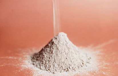
Figure 9.1.1. Portland cement is a fine, gray powder.
The data reported here are from a 1998 survey of portland cement mill test reports in the United States, conducted by PCA (Tennis, 1999). Other chapters* in this book detail specifications and types of cement from around the world. Although much of the discussion will apply to cements in other areas of the world, data provided is summarized from that collected predominantly from U.S. and Canadian cement plants.
HYDRAULIC CEMENTS
Hydraulic cements for general construction purposes are specified in the United States using ASTM C 150, ASTM C 595, and ASTM C 1157. A brief description of the major types of hydraulic cements listed in these specifications is provided here.
Types of Portland Cements
Different types of portland cement are manufactured to meet various normal physical and chemi-cal requirements for specific purposes. Portland cements are manufactured to meet the specifica-tions of ASTM C 150, or ASTM C 1157. ASTM C 150 provides for eight types of portland cement using Roman numeral designations as follows:
Type I Normal
Type IA Normal, air-entraining
Type II Moderate sulfate resistance
Type IIA Moderate sulfate resistance, air-entraining
Type III High early strength
Type IIIA High early strength, air-entraining
Type IV Low heat of hydration
Type V High sulfate resistance
ASTM C 1157 provides for six types of portland cement as discussed under “Hydraulic Cements” below. A detailed review of ASTM C 150 cements follows.
Type I. Type I portland cement is a general-purpose cement suitable for all uses where the special properties of other types are not required. Its uses in concrete include pavements, floors, rein-forced concrete buildings, bridges, tanks, reservoirs, pipe, masonry units, and precast concrete products.
Type II. Type II portland cement is used where precaution against moderate sulfate attack is important. It is used in normal structures or elements exposed to soil or ground waters where sulfate concentrations are higher than normal but not unusually severe (see Table 9.1.10). Type II cement has moderate sulfate resistant properties because it contains no more than 8% tricalcium aluminate (C3A). Sulfates in moist soil or water may enter the concrete and react with the hydrated C3A, resulting in expansion, scaling, and cracking of concrete. Some sulfate compounds, such as magnesium sulfate, directly attack calcium silicate hydrate.
Use of Type II cement in concrete must be accompanied by the use of a low water to cementitious materials ratio and low permeability to control sulfate attack.
Type II cements specially manufactured to meet the moderate heat option of ASTM C 150 will generate heat at a slower rate than Type I or most Type II cements. The requirement of moderate heat of hydration can be specified at the option of the purchaser. A cement in which heat-of-hydration maxima are specified can be used in structures of considerable mass, such as large piers, large foundations, and thick retaining walls. Its use will reduce temperature rise and temperature related cracking, which is especially important when concrete is placed in warm weather.
Some cements may be labeled with more than one type designation, for example Type I/II. This simply means that such a cement meets the requirements of both cement Types I and II.
Type III. Type III portland cement provides strength at an early period, usually a week or less. It is generally chemically and physically similar to Type I cement, except that its particles have been ground finer. It is used when forms need to be removed as soon as possible or when the structure must be put into service quickly. In cold weather its use permits a reduction in the length of the curing period. Although higher-cement content mixes of Type I cement can be used to gain high early strength, Type III may provide it easier and more economically.
Type IV. Type IV portland cement is used where the rate and amount of heat generated from hydration must be minimized. It develops strength at a slower rate than other cement types. Type IV cement is intended for use in massive concrete structures, such as large gravity dams, where the temperature rise resulting from heat generated during hardening must be minimized. Type IV cement is rarely available.
Type V. Type V portland cement is used in concrete exposed to severe sulfate action—principally where soils or groundwaters have a high sulfate content. It gains strength more slowly than Type I cement. Table 9.1.10 lists sulfate concentrations requiring the use of Type V cement. The high sulfate resistance of Type V cement is attributed to a low tricalcium aluminate content, not more than 5% and a low ferrite content. Use of a low water to cementitious materials ratio and low permeability are critical to the performance of any concrete exposed to sulfates. Even Type V cement concrete cannot withstand a severe sulfate exposure if the concrete has a high water to cementitious materials ratio. Type V cement, like other portland cements, is not resistant to acids and other highly corrosive substances. ASTM C 150 allows both a chemical approach and a physi-cal approach (ASTM C 452 expansion test) to assure the sulfate resistance of Type V cement. Either the chemical or the physical approach can be specified, but not both.
Air-entraining portland cements. Specifications for three types of air-entraining portland cement (Types IA, IIA, and IIIA) are given in ASTM C 150. They correspond in composition to Types I, II, and III, respectively, except that small quantities of air-entraining material are inter-ground with the clinker during manufacture. These cements produce concrete with improved resistance to freezing and thawing. Such concrete contains minute, well-distributed, and completely separated air bubbles. Air entrainment for most concretes is achieved through the use of an air-entraining admixture, rather than through the use of air-entraining cements. Air-entrain-ing cements are available only in certain areas.
Types of Blended Cements
Blended cements are used in all aspects of concrete construction in the same manner as portland cements. Blended cements can be used as the only cementitious material in concrete or they can be used in combination with other supplementary cementitious materials added at the concrete plant. Blended cements are often designed to be used in combination with local pozzolans and slags. If a blended cement or portland cement is used alone or in combination with added pozzolans or slags, the concrete should be tested for strength, durability, and other properties required in proj-ect specifications (PCA 1995 and Detwiler, Bhatty, and Bhattacharja 1996).
Blended hydraulic cements are produced by intimately and uniformly intergrinding or blending two or more types of fine materials. The primary materials are portland cement, ground granulated blast-furnace slag, fly ash, silica fume, calcined clay, other pozzolans, hydrated lime, and preblended combinations of these materials (Fig. 9.1.2). Blended hydraulic cements must conform to the requirements of ASTM C 595 or ASTM C 1157. ASTM C 595 recognizes five primary classes of blended cements as follows:
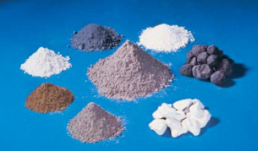
Figure 9.1.2. Blended cements use a combination of portland cement or clinker and gypsum blended or interground with pozzolans, slag, or fly ash. ASTM C 1157 allows the use and optimization of all these materials, simultaneously if neces-sary, to make a cement with optimal properties. Shown is blended cement (center) surrounded by (right and clockwise) clinker, gypsum, portland cement, fly ash, slag, silica fume, and calcined clay.
Type IS Portland blast-furnace slag cement
Type IP and Type P Type I(PM) Portland-pozzolan cement
Type S Slag cement
Type I(SM) Slag-modified portland cement
Types IS, IP, P, I(PM), and I(SM) are general purpose cements; these and subcategory types are reviewed in the discussion below. ASTM C 1157 provides for six types of blended cement as discussed under “Hydraulic Cements” below. Blended cements meeting the requirements of C 1157 meet physical performance test requirements without prescriptive restrictions on ingredients or cement chemistry. This allows the cement manufacturer to optimize strength and durability prop-erties through use of a variety of cementitious materials, such as portland clinker, fly ash, slag, silica fume, and calcined clay.
A detailed review of ASTM C 595 blended cements follows:
Type IS. Portland blast-furnace slag cement, Type IS, may be used in general concrete construc-tion. Historical use of slag blended cements dates back to the beginning of the 20th century in Europe, Japan, and North America (Abrams 1925). In producing these cements, granulated blast-furnace slag is either interground with portland cement clinker, separately ground and blended with portland cement, or produced with a combination of intergrinding and blending. The blast-furnace slag content of this cement is between 25% and 70% by mass. Subcategory types (optional special properties) such as air-entrainment, moderate sulfate resistance, or moderate heat of hydration may be specified by adding the suffixes A, MS, or MH. For example, an air-entraining portland blast-furnace slag cement that has moderate sulfate resistance would be designated as Type IS-A(MS). See Klieger and Isberner (1967) and PCA (1995).
Type IP and Type P. Portland-pozzolan cements are designated as Type IP or Type P. Type IP may be used for general construction and Type P is used in construction not requiring high early strengths. These cements are manufactured by intergrinding portland cement clinker with a suit-able pozzolan, by blending portland cement or portland blast-furnace slag cement and a pozzolan, or by a combination of intergrinding and blending. The pozzolan content of these cements is between 15% and 40% by mass. Laboratory tests indicate that performance of concrete made with Type IP cement as a group is similar to that of Type I cement concrete. Type IP may be designated as air-entraining, moderate sulfate resistant, or with moderate heat of hydration by adding the suffixes A, MS, or MH. Type P may be designated as low heat of hydration (LH), moderate sulfate resistant (MS), or air entraining (A).
Type I (PM). Pozzolan-modified portland cement, Type I(PM), is used in general concrete construction. The cement is manufactured by combining portland cement or portland blastfurnace slag cement and a fine pozzolan. This may be accomplished by either (1) blending port-land cement with a pozzolan, (2) blending portland blast-furnace slag cement with a pozzolan,(3) intergrinding portland cement clinker and a pozzolan, or (4) a combination of intergrinding and blending. The pozzolan content is less than 15% by mass of the finished cement. Air-entrain-ment, moderate sulfate resistance, or moderate heat of hydration may be designated in any combi-nation by adding the suffixes A, MS, or MH. An example of an air-entraining, moderate-heat-of-hydration Type I(PM) cement would be designated as Type I (PM)-A(MH).
Type S. Slag cement, Type S, is used with portland cement in making concrete or with lime in making mortar, but is not used alone in structural concrete. Slag cement is manufactured by either (1) blending ground granulated blastfurnace slag and portland cement, (2) blending ground gran-ulated blast-furnace slag and hydrated lime, or (3) blending a combination of ground granulated blastfurnace slag, portland cement, and hydrated lime. The minimum slag content is 70% by mass of the slag cement. Air-entrainment may be designated in a slag cement by adding the suffix A, for example, Type S-A.
Type I (SM). Slag-modified portland cement, Type I(SM), is used for general concrete construc-tion. This cement is manufactured by either (1) intergrinding portland cement clinker and granu-lated blast-furnace slag, (2) blending portland cement and finely ground granulated blast-furnace slag, or (3) a combination of intergrinding and blending. Slag is less than 25% by mass of the finished cement. Type I(SM) may be designated with air-entrainment, moderate sulfate resistance, or moderate heat of hydration by adding the suffixes A, MS, or MH. An example would be Type I(SM)-A(MH) for an air-entraining, slag-modified portland cement with moderate heat of hydration.
Types of Hydraulic Cements Under ASTM C 1157
Hydraulic cements set and harden by reacting chemically with water. They also stay hard and maintain their stability under water. They are used in all aspects of concrete construction. All port-land and blended cements are hydraulic cements. “Hydraulic cement” is merely a broader term. See also ASTM C 219 for terms relating to hydraulic cements.
The 1990s saw the creation of a performance specification for hydraulic cements—ASTM C 1157. This specification is designed generically for hydraulic cement to include portland cement, modi-fied portland cement, and blended hydraulic cement. Cements meeting the requirements of C 1157 meet physical performance test requirements, as opposed to prescriptive restrictions on ingredients or cement chemistry as found in other cement specifications. ASTM C 1157 provides for six types of hydraulic cement as follows:
Type GU General use
Type HE High early strength
Type MS Moderate sulfate resistance
Type HS High sulfate resistance
Type MH Moderate heat of hydration
Type LH Low heat of hydration
In addition, these cements can also have an Option R–Low Reactivity with Alkali-Reactive Aggregates—specified to help control alkali-silica reactivity. For example, Type GU-R would be a general-use hydraulic cement with low reactivity with alkali-reactive aggregates.
When specifying a cement under C 1157, the specifier uses the nomenclature of “hydraulic cement,” “portland cement,” “air-entraining portland cement,” “modified portland cement” or “blended hydraulic cement” along with a type designation. For example, a specification may call for a Hydraulic Cement Type GU, a Blended Hydraulic Cement Type MS, or a Portland Cement Type HS. If a type is not specified, then Type GU is assumed.
ASTM C 1157 defines a blended cement as having more than 15% mineral additive and a modified portland cement as containing up to 15% mineral additive. The mineral additive usually prefixes the modified portland cement nomenclature, for example, slag-modified portland cement. ASTM C 1157 also allows a strength range to be specified from a table in the standard. If a strength range is not specified, only the minimum strengths apply. Strength ranges are rarely applied in the United States. A detailed review of ASTM C 1157 cements follows:
Type GU. Type GU is a general-purpose cement suitable for all uses where the special properties of other types are not required. Its uses in concrete include pavements, floors, reinforced concrete buildings, bridges, pipe, precast concrete products, and other applications where Type I is used.
Type HE. Type HE cement provides higher strengths at an early age, usually a week or less. It is used in the same manner as Type III portland cement.
Type MS. Type MS cement is used where precaution against moderate sulfate attack is important, as in drainage structures where sulfate concentrations in ground waters are higher than normal but not unusually severe (see Table 9.1.10). It is used in the same manner as Type II portland cement. Like Type II, Type MS cement concrete must be made with a low water to cementitious materials ratio to provide sulfate resistance.
Type HS. Type HS cement is used in concrete exposed to severe sulfate action—principally where soils or ground waters have a high sulfate content (see Table 9.1.10). It is used in the same manner as Type V portland cement.
Type MH. Type MH cement is used where the concrete needs to have a moderate heat of hydra-tion and a controlled temperature rise. Type MH cement is used in the same manner as a moderate heat Type II portland cement.
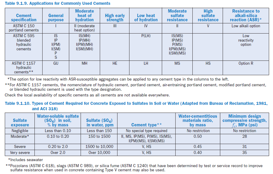
Type LH. Type LH cement is used where the rate and amount of heat generated from hydration must be minimized. It develops strength at a slower rate than other cement types. Type LH cement is intended for use in massive concrete structures where the temperature rise resulting from heat generated during hardening must be minimized. It is used in the same manner as Type IV portland cement. Table 9.1.9 provides a matrix of commonly used cements and where they are used in concrete construction.
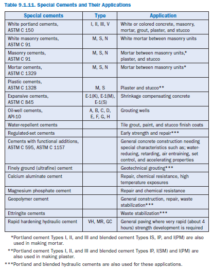
SPECIAL CEMENTS
A number of special cements are available as well,with particular characteristics developed for particular applications; however, their properties are beyond the scope of this review. Table 9.1.11 summarizes various special cements. See Odler (2000) and Klemm (1998) for more information.
CHEMICAL CHARACTERISTICS OF CEMENTS
Chemical analyses of portland and hydraulic cements are typically reported as oxide equivalents, although the elements are not necessarily present as oxides. This convention started with the early days of cement chemistry and provides for a convenient method of comparison.
Major elements in portland cement (as oxide equivalents) include, CaO, SiO2,Al2O3,Fe2O3, and MgO. For example, aluminum is reported as Al2O3,however, portland cement does not contain any free alumina. Instead aluminum is found as forms of calcium aluminate. The chemistry of the cement (along with kiln and cooler conditions) establish the amounts of the primary phases in the cement. Sulfate (reported as SO3) is present to control setting, as well as drying shrinkage and strength gain (Tang, 1992). Minor and trace elements and their effect on cement properties are discussed by Bhatty (1995) and PCA (1992). Minor oxides (in amount, not necessarily minor with regard to properties) include, Na2O, K2O, TiO2,P2O5,and many other compounds. These are largely included as impurities in the raw materials.
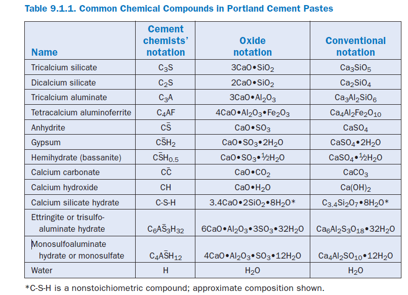
Because these oxides are combined in somewhat complicated compounds, cement chemists use the following chemical shorthand (abbreviations) in describing cement and its reactions:
A = Al2O3,C = CaO, C– = CO2,F = Fe2O3,H = H2O, M = MgO, S = SiO2, and Æ = SO3.
Thus, tricalcium silicate, Ca3SiO5 in conventional notation becomes 3CaO•SiO2 in oxide notation or C3S in cement chemists’ notation. See Table 9.1.1 for examples.
Methods of analysis are described in ASTM C 114. In cases of dispute, classical wet chemical meth-ods govern the results, but almost universally other so-called rapid instrumental techniques are used. Rapid methods are any analytical technique that can be demonstrated to give at least the level of precision stated in Table 1 of ASTM C 114. A common rapid method is X-ray fluorescence (XRF) spectroscopy.
Oxides
Portland cements are composed predominantly of calcium, silicon, aluminum, iron and sulfur, which are present as impure forms of C3S, C2S, C3A, and C4AF.
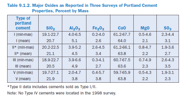
Table 9.1.2 reports ranges of major oxides in portland cement, along with the mean values (Tennis, 1999). Calcium is the most common cation in portland cement by mass with calcia accounting for between 60% and 68% by mass. Silica in the next most common oxide, amounting to about 19% to 23%. Alumina and iron oxide are the next most common constituents, but generally only are pres-ent in amounts less than 6% or so. Sulfates account for roughly 2% to 4% by mass. Selected minor elements are shown in Table 9.1.3.
Primary Phases
During the burning operation in the manufacture of portland cement clinker, calcium combines with the other components of the raw mix to form four principal chemical phases that typically make up more than 90% of cement by mass. Gypsum (4% to 6%), or other calcium sulfate source, is added during grinding, possibly along with other grinding aids. The four primary phases in portland cement and their approximate chemical formulas are
Tricalcium silicate C3S
Dicalcium silicate C2S
Tricalcium aluminate C3A
Tetracalcium aluminoferrite C4AF
Although the reporting of these phases is typically based on estimations provided by the Bogue calculations (Bogue, 1929; ASTM C 150), these and other phases may be directly determined through the use of microscopical techniques (ASTM C 1356, and Campbell, 1999) or X-ray diffrac-tion (XRD) (ASTM C 1365).
Common forms of calcium sulfate and their shorthand notation are:
Anhydrous calcium sulfate CÆ
Calcium sulfate dihydrate (gypsum) CÆ
Calcium sulfate hemihydrate CÆH1/2
Gypsum (calcium sulfate dihydrate) is the predominant source of sulfate used in cement. However, during milling, some of the gypsum is partially dehydrated by the heat generated and the other calcium sulfate forms are obtained; they are all readily soluble and contribute to setting control.
Present knowledge of cement chemistry indicates that the primary cement phases have the follow-ing properties:
Tricalcium silicate. Also referred to as alite or its shorthand notation, C3S, tricalcium silicate hydrates and hardens rapidly and is largely responsible for initial set and early strength (Figure 9.1.3). In general, the early strength is higher for portland cement concrete with increased percent-ages of C3S. Table 9.1.4 shows that the mean C3S content for all types of portland cements is 56%by mass, with some cements as low as 42% and some over 65%.
Dicalcium silicate. Dicalcium silicate is C2S, or belite, and hydrates slowly. It does however contribute appreciably to strength, although largely to strength development at ages beyond one week. Most portland cements contain between 10% and 30% by mass of C2S, with an average of about 17% (Table 9.1.4).
Tricalcium aluminate. Tricalcium aluminate, C3A, reacts rapidly and liberates a large amount of heat during the first few days of hydration and hardening. As noted earlier, calcium sulfates are added to control C3A from reacting rapidly, which can potentially cause setting problems. C3A contributes slightly to early strength development. Cements with low percentages of C3A are more resistant to soils and waters containing sulfates; for that reason specifications like ASTM C 150 limit the C3A content to a maximum of 8% by mass for Type II moderately sulfate resistant cements and to a maximum of 5% for Type V highly sulfate resistant cements. Type I and Type III cement range to about 14% by mass C3A in rare cases, with an average of about 9%. Type II cements range between about 3% and 8%, averaging 6%, while Type V cements range between 1%and 5%, averaging 4%.
Tetracalcium aluminoferrite. Also referred to as ferrite (or less often, brownmillerite), C4AF, is the product resulting from the use of iron and aluminum raw materials to reduce the clinkering temperature during cement manufacture. It contributes little to strength. Most color effects that make cement gray are due to C4AF. There is some evidence of a positive impact of higher C4AF contents on sulfate resistance (Lea, 1971). As shown in Table 9.1.4, portland cements are around 8% to 10% by mass C4AF on average, although the range is from 1% to 15%.
Calcium sulfate. Anhydrite (anhydrous calcium sulfate), gypsum (calcium sulfate dihydrate), or hemihydrate (also known as plaster of paris, or bassanite, or, formally, calcium sulfate hemihydrate) is added to cement during final grinding to provide sulfate to react with C3A to form ettringite (calcium trisulfoaluminate hydrate). This controls the hydration of C3A. Without sulfate, cements and concretes would set rapidly. In addition to controlling setting and early strength gain, the sulfate also helps control drying shrinkage and can influence strength through 28 days (Lerch, 1946).
The various forms of calcium sulfate are analyzed as SO3. This analysis also includes sulfate contributed from the clinker, generally in the form of alkali sulfates which are readily soluble and contribute to set control and other properties. A small amount may also be incorporated in the interior of cement grains, and thus may only become released as the cement hydrates. As shown in Table 9.1.2, U.S. cements contain between about 2% and 4.5% SO3.
Minor Elements
In addition to the primary cement phases, numerous other minor phases also are found in cements (PCA, 1992, Taylor, 1997). Bhatty (1995) reviewed literature on the effects of minor elements on cement properties. These elements (generally present at less than 1% by mass) are found in widely varying amounts in cements from plant to plant because they are present in different proportions in the raw materials available to each plant. Other sources of minor elements include fuel for combustion and even wear from refractory kiln linings and grinding media. Essentially all elements in the periodic table, in addition to those previously mentioned (Ca, Si, O, Al, S, Fe) might be found in portland cements. Therefore a complete discussion is not possible here.
Alkalies. The most common alkalies in portland cement are sodium and potassium. Their effects on cement behavior are to increase the OH– concentration of the pore solution. This generally increases the reaction rate for other hydration reactions and permits precipitation of calcium hydroxide, which helps maintain the high pH necessary for the chemical stability of the paste.
The high pH of pore solutions in cement-based materials can also react chemically with certain aggregate types in a generally (but not always) deleterious phenomenon known as alkali-silica reaction (ASR). A less common reaction (alkali-carbonate reaction, ACR) is also known, but restricted to particular geographic regions. In ASR, certain siliceous components of the aggregates react in the high pH pore solution to form a gel that may expand when exposed to moisture. The pressures generated by the expansion may be enough to cause cracking and deterioration of concrete structures. For more information, see the report by Farny and Kosmatka (1997).
Magnesia. Magnesia is limited by some specifications in order to prevent another deleterious expansive mechanism caused by the reaction between periclase (free MgO) and water to form brucite, Mg(OH)2.This is one possible source of unsoundness in cements, but is rarely encoun-tered in modern concrete. MgO is found in quantities of up to 6% in U.S. portland cements (Table 9.1.2), but only a portion of that is periclase, with the remainder being incorporated into other cement phases (Taylor, 1997). Cements are tested by the Autoclave Expansion Test (AET, ASTM C 151) which accelerates the reaction and allows unsound cements to be detected.
Free lime. Free lime (uncombined CaO) in cement is another possible source of unsoundness in cements due to its expansive reaction with water. It is also detected using the AET (or the LeChatelier method) and is not generally found in modern cements in sufficient quantities to be of concern. Free lime generally accounts for less than 1% by mass of portland cements.
Fly Ash, Pozzolans, and Slag
Materials such as fly ashes, pozzolans, and ground granulated blast furnace slags react in blended cements to generally improve the properties of concrete in the long term; however, as with any component of concrete mixtures, testing unfamiliar materials is necessary to acquaint the user with the properties of the material before use in the field. These materials, also known as supple-mentary cementitious materials (SCMs), generally react slower than portland cements and their inclusion as part of the cementitious materials may affect setting and strength development. Particular care in curing may be important as a result. However, when used in appropriate quanti-ties, long-term concrete strength is generally improved and durability is also often improved, due to reduced permeability of the concrete pore structure.
Other durability-enhancing mechanisms may be at work as well. For example, alkalies may be diluted or bound in the additional hydration products produced by these materials, and/or water demand might be reduced due to particle packing or shape effects, leading to a less permeable structure (Detwiler, 2002).
Although the chemistry and reactivity of these materials varies, the classic pozzolanic reaction, is a first approximation of the mechanism for increasing strength and durability by increasing the amount of C-S-H. The silicates in pozzolans react with calcium hydroxide (or with calcium in solution) to form additional C-S-H according to the following reaction:
CH + S → C-S-H
This additional C-S-H fills in porosity, making concrete or mortars less permeable to aggressive species or water.
Other reactions may also be important; for example, aluminum-bearing phases in fly ash (includ-ing in some cases C3A) can form calcium sulfoaluminate phases like the calcium aluminate phases in cement. This is important to bear in mind because the sulfate content of the cement, having been optimized for the cement aluminates alone, may not be sufficient to control the setting of the combined cement-fly ash system. This is a rare phenomena, but can lead to setting problems for concrete. Note that for fly ashes used in blended cements (i.e. not added when batching the concrete), this should not occur because the sulfate content of the final cement is optimized.
Proportions of fly ashes, pozzolans, and slags vary in blended cements due to material characteris-tics and optimization for particular properties. Limits (discussed earlier in this chapter) are provided in ASTM C 595 for some blended cements.
Fly ashes, pozzolans, and slags are also added to concrete as separate components of the mixture. In fact, the majority of concrete produced in the United States contains one of these supplemen-tary cementitious materials (SCMs). Data provided by a survey conducted by NRMCA in 1998 (PCA, 2000), indicate that 54% of concrete produced in the United States contained fly ash (on average 21% by mass of the cementitious materials). Further 9% contained ground, granulated blast-furnace slag (42% by mass on average). Less than 0.5% used other SCMs.
PHYSICAL PROPERTIES OF CEMENTS
Specifications for cement may place limits on both its physical properties and chemical composi-tion with respect to cement type. An understanding of the significance of the physical properties is helpful in interpreting test results. Tests of the physical properties of the cements should be used to evaluate the properties of the cement, rather than concrete. Cement should be sampled in accordance with ASTM C 183. During manufacture, cement is continuously monitored for its chemistry and the following properties:
Compressive Strength
Compressive strength as specified by ASTM cement standards is that obtained from tests of 50-mm (2-in.) mortar cubes tested in accordance with ASTM C 109 (Figure 9.1.4). These cubes, made using a standard sand (ASTM C 778), are fabricated and cured in a prescribed manner. Despite these well-defined procedures, the reproducibility of the test method is only moderate: acceptable differences in averages of two sets of properly-conducted tests are 11.3% at 3 days and 10.2% at 7days for a single laboratory. For multiple laboratories, the acceptable differences are 19.2% at 3days, and 18.1% at 7 days.
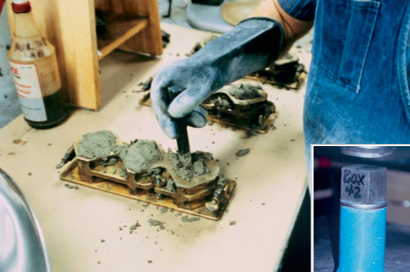
Figure 9.1.4. Mortar cubes are cast (left) and crushed (right) to determine strength characteristics of cement. (69128, 69124)
Compressive strength is influenced by the cement type, or more precisely, the phase composition and fineness of the cement. ASTM C 150, ASTM C 595, and ASTM C 1157 set minimum strength requirements. In addition, ASTM C 1157 also has options for maximum strength requirements. Minimum strength requirements in cement specifications are exceeded comfortably by most manufacturers. However, the strength development may be different for cements from different sources. Therefore, it should not be assumed that two types of cement meeting the same minimum requirements will produce the same strength of mortar or concrete without modification of mix proportions. In general, cement strengths (based on mortar-cube tests) cannot be used to predict concrete strengths with a great degree of accuracy because of the many variables in aggregate char-acteristics, concrete mixtures, construction procedures, and field conditions (Weaver, Isabelle and Williamson, 1970; DeHayes, 1990). Figure 9.1.5 illustrates the strength development for standard mortars made with various types of portland cement. Wood (1992) provides long-term strength properties of mortars and concretes made with portland and blended cements. The strength uniformity of a cement from a single source may be determined by following the procedures outlined in ASTM C 917.
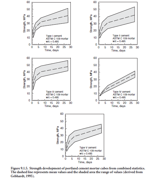
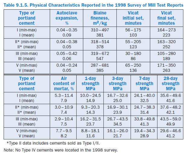
Table 9.1.5 provides a summary of the strength data for portland cements as determined using ASTM C 109. Early strengths are related to the cement fineness and composition and, broadly speaking, increase in the following order: Type V, Type II, Type I, and Type III. By 28 days, it is typical for any cement type to exceed 35 MPa in the standard test method.
Particle Size and Fineness
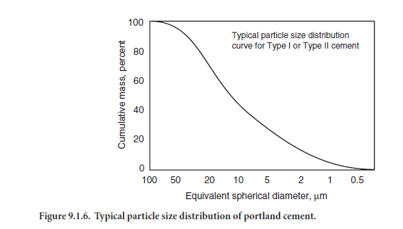
Portland cement consists of individual angular particles with a range of sizes, resulting from the pulverizing of clinker. Approximately 95% of cement particles are smaller than 45 µm, with the average particle around 15 µm. Figure 9.1.6 illustrates the particle size distribution for a portland cement. The overall particle size distribution of cement is called “fineness.” The fineness of cement affects heat released and the rate of hydration. Greater cement fineness (smaller particle size) increases the rate at which cement hydrates and thus accelerates strength development. The effects of greater fineness on paste strength are manifested principally during the first seven days.
In the early 1900s, cement fineness was expressed as the mass of cement per fractional size (percent weight retained on specific sieve sizes). Today, fineness is usually measured by the Blaine air-permeability test (ASTM C 204 – Figure 9.1.7) that indirectly measures the surface area of the cement particles per unit mass. Cements with finer particles have more surface area in square meters per kilogram of cement. Most cement standards do not have a maximum limit on fineness, only a minimum. The Wagner turbidimeter test (ASTM C 115), the 45-µm (No. 325) sieve (ASTM C 430) or the 150-µm (No. 100) and 75-µm (No. 200) sieve (ASTM C 184), and the electronic (x-ray or laser) particle size analyzer can also be used to test fineness.
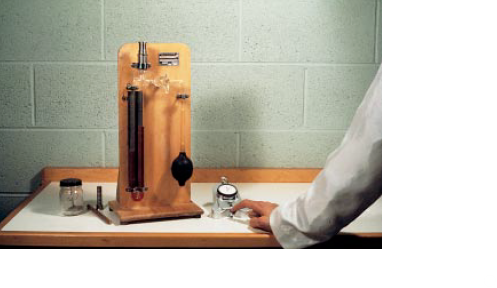
Figure 9.1.7. Blaine test apparatus for measuring cement fineness. (40262)
Data reported in the 1998 survey indicate typical finenesses for Type I, II, and V cements are about 380 m2/kg. Type III cements are much finer on average, almost 550 m2/kg (see Table 9.1.5). However, the range of values for finenesses that might be encountered in practice ranges from about 300 m2/kg to over 650 m2/kg.
Soundness
Soundness refers to the ability of a hardened paste to retain its volume. Lack of soundness, or delayed destructive expansion, can be caused by excessive amounts of hard burned free lime or magnesia. Most specifications for portland cement limit the magnesia (MgO) content (as a means of controlling the peri-clase content) and the maximum expansion as meas-ured by the autoclave-expansion test. In ASTM C 150, the maximum limit for MgO is 6% and the maximum autoclave expansion limit is 0.80%. Since the adop-tion of ASTM C 151 autoclave expansion test, there have been only a few cases of abnormal expansion attributed to unsound cement (Figure 9.1.8). Table 9.1.5 indicates expansion values reported on mill test reports range from about –0.04 to about 0.40 irre-spective of cement type. For more information, see Gonnerman, Lerch, and Whiteside (1953).
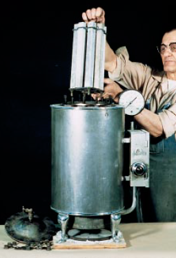
Figure 9.1.8. In the autoclave expansion test for soundness, 25 mm square bars are exposed to high temperature and pressure to determine the volume stability of the cement paste. (23894)
It should be noted that the autoclave expansion test (AET) has been criticized as being a severe test and many countries in the world test soundness via the LeChatelier method. Whereas the AET measures expansion on paste bars (25 mm × 25 mm cross section) exposed to steam at 2 MPa (approxi-mately 216°C) for 3 hours, the LeChatelier method (EN196-3) measures the expansion between needles attached to a split-ring mold, 30 mm in diameter and 30 mm high after 3 hours under boiling water. Due to the lower temperature, the LeChatelier method is generally considered less severe, and it may detect soundness problems due to free lime, but not periclase.
Consistency
Consistency refers to the relative mobility (ability to flow) of a freshly mixed cement paste or mortar. During cement testing, pastes are mixed to normal consistency as defined by a penetration of 10 ± 1 mm of the Vicat plunger (see ASTM C 187 and Figure 9.1.9). Mortars are mixed to obtain either a fixed water:cement ratio or to yield a flow within a prescribed range. The flow is deter-mined on a flow table (Figure 9.1.10) as described in ASTM C 230 according to test method ASTM C 1437. Both the normal consistency method and the flow test are used to regulate water contents of pastes and mortars, respectively, to be used in subsequent tests; both allow comparing dissimilar ingredients with the same penetrability or flow. According to ASTM C 187, single-operator tests should not differ by more than 0.7% and multi-laboratory tests should not differ by more than 1%. According to ASTM C 1437, the results of properly conducted tests should differ by no more than 11% for single-operator testing, or by 31% for multiple laboratory testing.
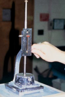
Figure 9.1.9. Normal consistency test for paste using the Vicat plunger. (68820).
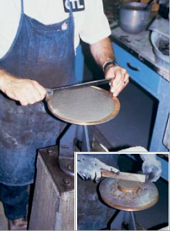
Figure 9.1.10 . Consistency test for mortar using the flow table. The mortar is placed in a small brass mold centered on the table (inset). After the mold is removed and the table undergoes a succes-sion of drops, the diameter of the pat is measured to determine consistency. For skin safety, the tech-nician wears protective gloves. (68821, 68822).
Setting Time
The object of the setting time test is to determine; 1) the time that elapses from the moment water is added until the paste ceases to be fluid and plastic (called initial set) and, 2) the time required for the paste to acquire a certain degree of hardness (called final set).
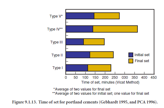
To determine if a cement sets according to the time limits specified in cement specifications, tests are performed using either the Vicat apparatus (ASTM C 191 – Figure 9.1.11) or the Gillmore needle (ASTM C 266 – Figure 9.1.12). The Vicat test governs if no test method is specified by the purchaser. Initial set of cement paste must not occur too early and final set must not occur too late. The setting times indicate that a paste is or is not undergoing normal hydration reactions. Sulfate (from gypsum or other sources) in the cement regulates setting time, but setting time is also affected by cement fineness, water-cement ratio, and any admixtures that may be used. Setting times of concretes do not correlate directly with setting times of pastes because of water loss to the air or substrate, presence of aggregate, and because of temperature differences in the field (as contrasted with the controlled temperature in a testing lab). Figure 9.1.13 illustrates average set times for portland cements. Although specific cements may not follow the trend, Type III cements set quickest, followed in order by Type I, Type II, Type V and Type IV. Table 9.1.5 provides mean values and ranges according to the Vicat test
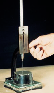
Figure 9.1.11. Vicat needle apparatus used for determining time of set. (23890)
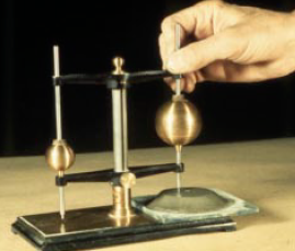
Figure 9.1.12. Gillmore apparatus used as one method of determining time of set. Note results will not be the same as with the Vicat apparatus. (23892).
 4
4
Early Stiffening (False Set and Flash Set)
Early stiffening is the early development of stiffness in the working characteristics or plasticity of cement paste, mortar, or concrete. This includes both false set and flash set. False set is evidenced by a significant loss of plasticity without the evolution of much heat shortly after mixing.*
From a placing and handling standpoint, false-set tendencies in cement will cause no difficulty if the concrete is mixed for a longer time than usual or if it is remixed without additional water before being transported or placed. False set occurs when a significant amount of gypsum dehy-drates in the cement mill to form plaster. Stiffening is caused by the rapid re-crystallization and interlocking of needle-like secondary gypsum. Additional mixing without added water breaks up these crystals to restore workability. Ettringite precipitation can also contribute to false set. Flash set or quick set is evidenced by a rapid and early loss of workability; it is usually accompanied by the evolution of considerable heat resulting primarily from the rapid reaction of aluminates. If the proper amount or form of calcium sulfate is not available to control the calcium aluminate hydration, stiffening becomes apparent. Flash set cannot be dispelled, nor can the plasticity be regained by further mixing without the addition of water.
Proper stiffening results from the careful balance of the sulfate and aluminate phases, as well as the temperature and fineness of the materials (which control the hydration and dissolution rates). The amount of sulfate formed into plaster has a significant effect. For example with one particular cement, 2% plaster allowed a 5 hour set time, while 1% plaster caused flash set to occur, and 3%allowed false set to occur (Helmuth, et al., 1995). Cements are tested for early stiffening using ASTM C 451 (paste method), and ASTM C 359 (mortar method), which use the penetration tech-niques of the Vicat apparatus. However, these tests do not address all the mixing, placing, tempera-ture, and field conditions that can cause early stiffening. They also do not address early stiffening caused by interactions with other concrete ingredients. For example, concretes mixed for very short periods (less than a minute) tend to be more susceptible to early stiffening (ACI 225).
Heat of Hydration
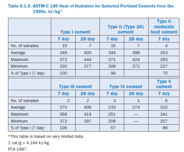
Heat of hydration is the heat generated when cement and water react. The amount of heat gener-ated is dependent chiefly upon the chemical composition of the cement, with C3A and C3S being the phases primarily responsible for high heat evolution. The water-cement ratio, fineness of the cement, and temperature of curing also are factors. An increase in the fineness, cement content, and curing temperature increases the heat of hydration. Although portland cement can evolve heat for many years, the rate of heat generation is greatest at early ages. A large amount of heat evolves within the first three days with the greatest rate of heat liberation usually occurring within the first 24 hours (Copeland, et al., 1960). The heat of hydration is tested in accordance with ASTM C 186 or by conduction calorimetry.
For most concrete elements, such as slabs, heat generation is not a concern because the heat is quickly dissipated into the environment. However, in structures of considerable mass, greater than a meter thick, the rate and amount of heat generated are important. If this heat is not rapidly dissi-pated, a significant rise in concrete temperature can occur. This may be undesirable since, after hardening at an elevated temperature, nonuniform cooling of the concrete mass to ambient temperature may create undesirable tensile stresses. On the other hand, a rise in concrete tempera-ture caused by heat of hydration is often beneficial in cold weather since it helps maintain favor-able curing temperatures.
Table 9.1.6 provides heat of hydration values for different portland cements. This limited data show that Type III cement has a higher heat of hydration than other types while Type IV has the lowest. Also note the difference in heat generation between regular Type II cements and moderate heat Type II cements.
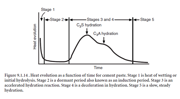
Cements do not generate heat at a constant rate. The heat output during hydration of a typical Type I portland cement is illustrated in Figure 9.1.14. The first peak shown in the heat profile is due to heat given off by the initial hydration reactions of cement phases such as tricalcium alumi-nate. Sometimes called the heat of wetting, this first heat peak is followed by a period of slow activ-ity known as the induction period. After several hours, a broad second heat peak attributed to tricalcium silicate hydration emerges, signaling the onset of the paste hardening process. Finally, there is the third peak due to the renewed activity of tricalcium aluminate; its intensity and loca-tion is normally dependent on the amount of tricalcium aluminate and sulfate in the cement.
In calorimetry testing, the first heat measurements are obtained a few minutes after mixing the paste; as a result only the downward slope of the first peak is observed (Stage 1, Figure 9.1.14). The second peak (C3S peak) often occurs between 6 and 12 hours. The third peak (renewed C3A peak on conversion of ettringite to monosulfate) occurs between 12 and 90 hours. This information can be helpful when trying to control temperature rise in mass concrete (Tang 1992). When heat gener-ation must be minimized in concrete, designers should choose a lower heat cement, such as a Type II portland cement with the optional moderate heat of hydration requirements.
Not all Type II cements are made for a moderate level of heat development, however, so the moderate heat option must be specifically requested. Type IV cement can also be used to control temperature rise, but it is rarely available. Moderate-heat and low-heat cements are also available in ASTM C 595 and C 1157 specifications. Supplementary cementitious materials (SCMs) can also be used to reduce temperature rise.
ASTM C 150 has both a chemical approach and a physical approach to control heat of hydration. Either approach can be specified, but not both. ASTM C 595 and ASTM C 1157 use physical limits. See PCA (1997) for more information.
Loss on Ignition
Loss on ignition (LOI) of portland cement is determined by heating a cement sample of known weight to between 900°C and 1000°C until a constant weight is obtained. The weight loss of the sample is then determined. Normally, a high loss on ignition is an indication of prehydration and carbonation, which may be caused by improper or prolonged storage, or adulteration during transport. The test for loss on ignition is performed in accordance with ASTM C 114. Loss on igni-tion values range from about 0% to 3% (Table 9.1.3).
Density, Relative Density (Specific Gravity), and Bulk Density
The density of cement is defined as the mass of a unit volume of the solids or particles, excluding air between particles. It is reported as megagrams per cubic meter or grams per cubic centimeter (the numeric value is the same for both units). The particle density of portland cement ranges from 3.10 to 3.25, averaging 3.15 Mg/m3.Portland blast-furnace-slag and portland-pozzolan cements have densities ranging from 2.90 to 3.15, averaging 3.05 Mg/m3. The density of a cement, determined by ASTM C 188 (Figure 9.1.15), is not an indication of the cement’s quality; its princi-pal use is in mix proportioning calculations. Properly conducted measurements by the same operator should differ by no more than 0.03 Mg/m3, and measurements between laboratories should differ by no more than 0.10 Mg/m3.
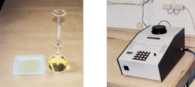
Figure 9.1.15. Density of cement can be determined by using a Le Chatelier flask and kerosene (left) or by using a helium pycnometer (right). (68825, 68826)
For mix proportioning, it may be more useful to express the density as relative density (also called specific gravity). The relative density is a dimensionless number determined by dividing the cement density by the density of water at 4°C. The density of water at 4°C is 1.0 Mg/m3 (1.0 g/cm3 or 1000 kg/m3).
A relative density of 3.15 is generally assumed for portland cement in volumetric computations of concrete mix proportioning. However, as mix proportions list quantities of concrete ingredients in kilograms or pounds, the relative density must be multiplied by the density of water at 4°C stated as 1000 kg/m3 to determine the particle density in appropriate units. This product is then divided into the mass or weight of cement to determine the absolute volume of cement.
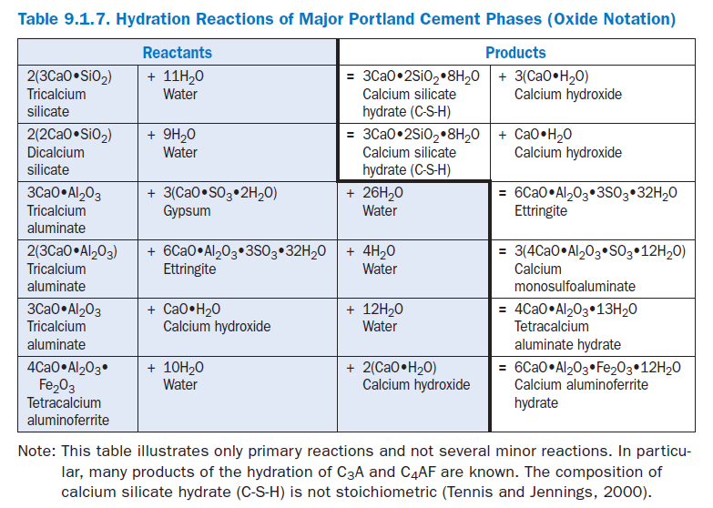
The bulk density of cement is defined as the mass of cement particles plus air between parti-cles per unit volume. The bulk density of cement can vary considerably depending on how it is handled and stored. Portland cement that is fluffed up may weigh only 830 kg/m3, whereas when consolidated by vibration, the same cement can weigh as much as 1650 kg/m3 (Toler, 1963). For this reason, good practice dictates that cement must be weighed for each batch of concrete produced, as opposed to use of a volumetric measure (Figure 9.1.16).
Figure 9.1.16. Both 500 ml beakers contain 500 g of dry cement. On the left, cement was simply poured into the beaker, while on the right, the cement was slightly vibrated – imitating consoli-dation during transport or packing while in a silo. The 20% difference in bulk volume demonstrates the need to measure cement by mass rather than volume for batching concrete. (68970)
Air Content
The air content of a standard mortar is also reported on many mill test reports as air entrained in concrete will typically decrease the strength. Entrained air in concrete is a benefit to freeze-thaw resistance if the air bubble size and spacing are of the proper size (Whiting and Nagi 1998) as it allows freezing water a space to expand into without cracking concrete. However unintended entrained air could result in unacceptable strength levels. Non-air entraining portland cements are required to contain less than 12% air in standard mortars (ASTM C 185), while air-entraining cements are required to contain between 16% and 22% air. Table 9.1.5 reports averages for ASTM C 150 portland cements produced in the United States, which average around 7.5% and range from about 3% to 11%.
CEMENT HYDRATION
Basic Reactions
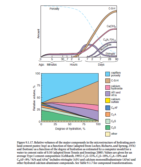
In the presence of water, the major cementing phases hydrate (chemically react with water) to form new phases that are the infrastructure of hardened cement paste in concrete. The calcium silicates, C3S and C2S, hydrate to form calcium hydroxide (CH) and calcium silicate hydrate (C-S-H), archaically called tobermorite gel. Hydrated portland cement contains 15% to 25% calcium hydroxide and about 50% calcium silicate hydrate by mass. The strength and other properties of hydrated cement are due primarily to calcium silicate hydrate. C3A reacts with water and calcium hydroxide to form tetracalcium aluminate hydrates. C4AF reacts with water to form calcium aluminoferrite hydrates. C3A, sulfates (gypsum, anhydrite, or other sulfate source), and water combine to form calcium trisulfoaluminate hydrate (ettringite), calcium monosulfoaluminate, and other related phases. These basic reactions are shown in Table 9.1.7. Over the years, Brunauer (1957), Copeland and coworkers (1960), Lea (1971), Powers and Brownyard (1947), Powers (1961), and Taylor (1997) have comprehensively addressed the science of pore structure and chemistry of cement paste. Figure 9.1.17 shows estimates of the relative volumes of the phases in hydrated port-land cement pastes. A web-based computer model for hydration and microstructure development can be found at http://vcctl.cbt.nist.gov. The approximate percentage of each phase can be calculated from a chemical oxide analysis (ASTM C 114) of the unhydrated cement per ASTM C 150 (Bogue calculations). Due to the assumptions inherent in the Bogue calculations, X-ray diffraction techniques (ASTM C 1365) and optical microscopy (ASTM C 1356) can often more accurately determine phase percentages.
Water (Evaporable and Nonevaporable)
Water is a key ingredient of pastes, mortars, and concretes, as the phases in portland cement must chemically react with water to develop strength. The amount of water added to a mixture controls the durability as well. The space initially taken up by water in a cementitious mixture is partially or completely replaced over time as the hydration reactions proceed. If more than about 35% water by mass of cement – a water to cement ratio of 0.35 – is used, then porosity in the hardened mate-rial will remain even after complete hydration. This is called capillary porosity. Figure 9.1.18 shows that cement pastes with high and low water to cement ratios have equal masses after drying (evap-orable water was removed). The cement consumed the same amount of water in both pastes result-ing in more bulk volume in the higher water-cement ratio paste. As the water to cement ratio increases, the capillary porosity increases, and the strength decreases. Also, transport properties such as permeability and diffusivity are increased, allowing detrimental chemicals to more readily attack the concrete or reinforcing steel.
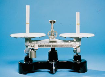
Figure 9.1.18. Cement paste cylinders of equal mass and equal cement content, but mixed with different water to cement ratios, after all water has evaporated from the cylinders. (1072).
Water is found in cementitious materials in several forms. Free water is mixing water that has not reacted with the cement phases. Bound water is chemically combined in the solid phases or physi-cally bound to the solid surfaces. A reliable separation of the chemically combined water from the physically adsorbed water is not possible. Therefore it is useful to distinguish between evaporable and nonevaporable water (Powers, 1949). The nonevaporable water is the amount retained by a sample after it has been subjected to a drying procedure intended to remove all the free water (traditionally, by heating to 105°C). Evaporable water was originally considered to be free water, but it is now recognized that some bound water is also lost upon heating to this temperature. All nonevaporable water is bound water, but the opposite is not true.
For complete hydration of portland cement, only about 40% water by mass (a water-to-cement ratio of 0.40) is needed. If a water-to-cement ratio greater than about 0.40 is used, the excess water not needed for cement hydration remains in the capillary pores or evaporates. If a water-to-cement ratio less than about 0.40 is used, some cement will remain unhydrated. To estimate the degree of hydration of a hydrated material the nonevaporable water content is often used. To convert the measured nonevaporable water into degrees of hydration, it is necessary to know the value of nonevaporable water-to-cement ratio (wn/c) at complete hydration.
Experimentally, this can be determined by preparing a high water-to-cement ratio cement paste (for example, 1.0) and continuously grinding while it hydrates in a roller mill. In this procedure, complete hydration of the cement will typically be achieved after 28 days.
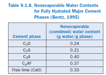
Alternatively, an estimate of the value of nonevaporable water to-cement ratio (wn/c) at complete hydration can be obtained from the potential Bogue compo-sition of the cement. Nonevaporable water contents for the major phases of portland cement are provided in Table 9.1.8. For a typical Type I cement, these water contents will generally result in a calculated wn/c for completely hydrated cement somewhere between 0.22 and 0.25.
APPLICATIONS
Table 9.1.9 lists cement types defined in ASTM C 150, C 595, and C 1157 as well as their intended applications. Performance of different cement types for the same application may not be the same, but minimum performance of the cement is assured. In addition, it should be noted that many properties of engineering significance are properties of the concrete, which is influenced by cement characteristics, but not wholly controlled by them. Other important factors include the propor-tions of other materials (water, aggregates, SCMs, chemical admixtures, air), their characteristics (quality, gradation, chemistry, consistency), handling of the concrete (mixing, placing, finishing, curing), as well environmental conditions (temperature, relative humidity, wind speed, freezing and thawing) to which it is exposed. Especially important are the early age conditions of concrete.
In situations where reactive aggregates must be used it is recommended that cementitious materi-als and aggregates be tested to assure performance (Farny and Kosmatka, 1997) unless sufficient past experience with the materials can provide assurance. Generally low-alkali portland cements, provide protection for many (but not all) aggregates. Blended cements are likely to also perform well, but must be tested beforehand.
If concrete will be exposed to high concentrations of sulfate, sulfate-resistant cements may be of use. For portland cements, these are typically specified by maximum C3A contents: Type II cements (moderately sulfate resistant) have a maximum 8% C3A, and Type V (sulfate resistant cements) contain a maximum of 5% C3A and a maximum of (C4AF + 2[C3A]) of 25%. Sulfate resistant cements specified under ASTM C 595 (MS designation) and ASTM C 1157 (Types MS and HS) have performance requirements for sulfate resistance. Table 9.1.10 summarizes require-ments for concrete in sulfate environments.
It should be emphasized that cementitious material selection is useful, but not sufficient to guar-antee sulfate resistance in concrete. Concrete permeability is important as well. A highly-sulfate resistant cement may be used in a highly permeable concrete and may still be degraded in some environments. As well, a less sulfate-resistant cement might perform satisfactorily in a very imper-meable concrete (Stark, 2002). If materials are to be used in an aggressive environment, it is recommended that concrete be tested in as close a manner as possible to field conditions.
For large concrete pours (mass concrete) the heat released by the hydrating cementitious materials may cause an increase in concrete temperature sufficient to cause concern. Two issues arise. First, as in all materials if a difference in temperature across a specimen is large enough tensile stresses are generated which may be sufficient to cause cracking. This may happen for example in a mass concrete placement where the center of the concrete is quite warm due to hydration, but ambient temperature is much lower (for example at night). For such an application, Type IV portland cements or in some cases Type II cements may be suitable. ASTM C 150 also provides for an optional performance test to determine the heat evolved with a particular cement. ASTM C 595 cement types with the MH designation have also been tested. ASTM C 1157 Types MS and HS are also formulated to generate less heat. Use of blended cements or sufficient quantities of some SCMs can also reduce the heat generated.
A second problem that may arise from too much heat being evolved, is a phenomenon known as delayed ettringite formation (DEF) or heat-induced delayed expansion (HIDE). Although the mechanisms behind DEF are not completely understood, it occurs only when excessive concrete temperatures are reached during concrete curing.Subsequently, premature deterioration may result. For this reason, precautions are taken with mass concrete placements, and in accelerated curing operations, such as precast plants.
Johansen and Taylor (2004) discuss how cement characteristics affect concrete performance in much more detail.
REFERENCES
Technical Literature
Abrams, Duff A., “Effect of Hydrated Lime and Other Powdered Admixtures in Concrete,” Proceedings of the American Society for Testing Materials, Vol. 20, Part 2, 1920. Reprinted with revi-sions as Bulletin 8, Structural Materials Research Laboratory, Lewis Institute, June 1925, 78 pages.
Bentz, D. P., A Three-Dimensional Cement Hydration and Microstructure Program. Part I: Hydration Rate, Heat of Hydration, and Chemical Shrinkage, NISTIR 5756, National Institute of Standards and Technology, Gaithersburg, Maryland, November 1995, 60 pages.
Bhatty, J. I., Effects of Minor Elements on Cement Manufacture and Use, Research and Development Bulletin RD109, Portland Cement Association, 1995, 48 pages.
Bogue, R. H., “Calculation of the Compounds in Portland Cement,” Industrial Engineering and Chemistry, Vol. 1, No. 4, 1929, pages 192-199.
Brunauer, S., Some Aspects of the Physics and Chemistry of Cement, Research Department Bulletin RX080, Portland Cement Association, http://www.cement.org/pdf_files/RX080.pdf, 1957, 43 pages.
Bureau of Reclamation, Concrete Manual, 8th ed., U.S. Bureau of Reclamation, Denver, Colorado, 1981.
Copeland, L. E.; Kantro, D. L.; and Verbeck, G., Chemistry of Hydration of Portland Cement, Research Department Bulletin RX153, Portland Cement Association,
http://www.cement.org/pdf_files/RX153.pdf, 1960, 44 pages.
Campbell, D. H., Microscopical Examination and Interpretation of Portland Cement and Clinker, SP030, Portland Cement Association, 1999.
DeHayes, S. M., “C 109 vs. Concrete Strengths,” Proceedings of the Twelfth International Conference on Cement Microscopy, International Cement Microscopy Association, Duncanville, Texas, 1990.
Detwiler, R. J., Substitution of Fly Ash for Cement or Aggregate in Concrete: Strength Development and Suppression of ASR, RD127, Portland Cement Association, 2002, 28 pages.
Detwiler, R. J.; Bhatty, J. I.; and Bhattacharja, S., Supplementary Cementing Materials for Use in Blended Cements, RD112, Portland Cement Association, 1996, 108 pages.
Farny, J. A., and Kosmatka, S. H., Diagnosis and Control of Alkali-Aggregate Reactions in Concrete, IS413, Portland Cement Association, 1997, 24 pages.
Gebhardt, R. F., “Survey of North American Portland Cements: 1994,” Cement, Concrete, and Aggregates, American Society for Testing and Materials, West Conshohocken, Pennsylvania, December 1995, pages 145-189.
Gonnerman, H. F.; Lerch, William; and Whiteside, Thomas M., Investigations of the Hydration Expansion Characteristics of Portland Cements, Research Department Bulletin RX045, Portland Cement Association, http://www.cement.org/pdf_files/RX045.pdf, 1953, 181 pages.
Helmuth, R.; Hills, L. M.; Whiting, D. A.; and Bhattacharja, S., Abnormal Concrete Performance in the Presence of Admixtures, RP333, Portland Cement Association, 1995, 94 pages.
Johansen, V., and Taylor, P., Effects of Cement Characteristics on Concrete Properties, EB226, Portland Cement Association, Illinois, 2004.
Klemm, W. A., Ettringite and Oxyanion-Substituted Ettringites—Their Characterization and Applications in the Fixation of Heavy Metals: A Synthesis of the Literature, RD116, Portland Cement Association, 1998, 80 pages.
Lea, F. M., The Chemistry of Cement and Concrete, 3rd ed., Chemical Publishing Co., Inc., New York, 1971.
Lerch, W., The Influence of Gypsum on the Hydration and Properties of Portland Cement Pastes, Research Department Bulletin RX012, Portland Cement Association,
http://www.cement.org/pdf_files/RX012.pdf, 1946, 42 pages.
Locher, F. W.; Richartz, W.; and Sprung, S. “Setting of Cement—Part I: Reaction and Development of Structure,” ZKG International, Volume 29, Number 10, 1976, pages 435-442.
Odler, I., Special Inorganic Cements, E&FN Spon, NewYork, 2000, 420 pages.
PCA, Survey of Mineral Admixtures and Blended Cements in Ready Mixed Concrete, Market Research Report, Portland Cement Association, October 2000, 15 pages.
PCA, “Portland Cement, Concrete, and Heat of Hydration,” Concrete Technology Today, PL972, Portland Cement Association, Volume 18, No. 2, July 1997, pages 1-4.
PCA, Emerging Technologies Symposium on Cements for the 21st Century, SP206, Portland Cement Association, 1995, 140 pages.
PCA, An Analysis of Selected Trace Metals in Cement and Kiln Dust, SP109, Portland Cement Association, 1992, 51 pages.
Powers, T. C., Some Physical Aspects of the Hydration of Portland Cement, Research Department Bulletin RX126, Portland Cement Association, http://www.cement.org/pdf_files/RX126.pdf, 1961, 22 pages.
Powers, T. C., The Nonevaporable Water Content of Hardened Portland Cement Paste—Its Significance for Concrete Research and Its Method of Determination, Research Department Bulletin RX029, Portland Cement Association, http://www.cement.org/pdf_files/RX029.pdf, 1949, 21 pages.
Powers, T. C., and Brownyard, T. L., Studies of the Physical Properties of Hardened Portland Cement Paste, Research Department Bulletin RX022, Portland Cement Association, http://www.cement.org/pdf_files/RX022.pdf, 1947, 356 pages.
Stark, D. C., Performance of Concrete in Sulfate Environments, RD129, Portland Cement Association, 2002, 28 pages.
Tang, F.J.,Optimization of Sulfate Form and Content, Research and Development Bulletin RD105, Portland Cement Association, 1992, 44 pages.
Taylor, H.F.W.,Cement Chemistry, Thomas Telford Publishing, London, 1997, 477 pages.
Tennis, P. D., and Jennings, H. M., “A Model for Two Types of Calcium Silicate Hydrate in the Microstructure of Portland Cement Pastes,” Cement and Concrete Research, Pergamon, June 2000, pages 855-863.
Tennis, P. D., “Portland Cement Characteristics—1998,” Concrete Technology Today, PL992, Portland Cement Association, Volume 20, Number 2, August 1999, pages 1-3.
Toler, H. R., Flowability of Cement, Research Department Report, MP-106, Portland Cement Association, October 1963.
Weaver, W. S.; Isabelle, H. L.; and Williamson, F., “A Study of Cement and Concrete Correlation,” Journal of Testing and Evaluation, American Society for Testing and Materials, West Conshohocken, Pennsylvania, January 1974, pages 260-280.
Whiting, D.A., and Nagi, M. A., Manual on Control of Air Content in Concrete, EB116, National Ready Mixed Concrete Association and Portland Cement Association, 1998, 42 pages.
Wood, S.L., Evaluation of the Long-Term Properties of Concrete, Research and Development Bulletin RD102, Portland Cement Association, 1992, 99 pages.
Standards Referenced
ACI Committee 225, Guide to the Selection and Use of Hydraulic Cements, ACI 225, ACI Committee 225 Report, American Concrete Institute, Farmington Hills, Michigan, 1999.
ACI Committee 318, Building Code Requirements for Structural Concrete, ACI Committee 381 Report, American Concrete Institute, Farmington Hills, Michigan, 2002.
ASTM C 109 Standard Test Method for Compressive Strength of Hydraulic Cement Mortars (using 50 mm [2 in.] Cube Specimens), ASTM, West Conshohocken, Pennsylvania.
ASTM C 114 Standard Test Methods for Chemical Analysis of Hydraulic Cement
ASTM C 115 Standard Test Method for Fineness of Portland Cement by the Turbidimeter
ASTM C 150 Standard Specification for Portland Cement
ASTM C 151 Standard Test Method for Autoclave Expansion of Portland Cement
ASTM C 183 Standard Practice for Sampling and the Amount of Testing of Hydraulic Cement ASTM C 184 Standard Test Method for Fineness of Hydraulic Cement by the 150-µm (No. 100) and 75-µm (No. 200) Sieves
ASTM C 185 Standard Test Method for Air Content of Hydraulic Cement Mortar
ASTM C 186 Standard Test Method for Heat of Hydration of Hydraulic Cement
ASTM C 187 Standard Test Method for Normal Consistency of Hydraulic Cement
ASTM C 188 Standard Test Method for Density of Hydraulic Cement
ASTM C 191 Standard Test Method for Time of Setting of Hydraulic Cement by Vicat Needle
ASTM C 204 Standard Test Method for Fineness of Hydraulic Cement by Air Permeability Apparatus ASTM C 230 Standard Specification for Flow Table for Use in Tests of Hydraulic Cement
ASTM C 266 Standard Test Method for Time of Setting of Hydraulic-Cement Paste by Gillmore Needles
ASTM C 359 Standard Test Method for Early Stiffening of Portland Cement (Mortar Method)
ASTM C 430 Standard Test Method for Fineness of Hydraulic Cement by the 45-µm (No. 325) Sieve ASTM C 451 Standard Test Method for Early Stiffening of Hydraulic Cement (Paste Method)
ASTM C 595 Standard Specification for Blended Hydraulic Cements
ASTM C 778 Standard Specification for Standard Sand
ASTM C 917 Standard Test Method for Evaluation of Cement Strength Uniformity From a Single Source
ASTM C 1012 Standard Test Method for Length Change of Hydraulic-Cement Mortars Exposed to a Sulfate Solution
ASTM C 1038 Standard Test Method for Expansion of Portland Cement Mortar Bars Stored in Water
ASTM C 1157 Standard Performance Specification for Hydraulic Cement
ASTM C 1356 Standard Test Method for Quantitative Determination of Phases in Portland Cement Clinker by Microscopical Point-Count Procedure
ASTM C 1365 Standard Test Method for Determination of the Proportion of Phases in Portland Cement and Portland-Cement Clinker Using X-Ray Powder Diffraction Analysis
ASTM C 1437 Standard Test Method for Flow of Hydraulic Cement Mortar
EN 196-3 Methods of Testing Cement – Part 3: Determination of Setting Time and Soundness