Contents
cyclone suspension preheater
[wpecpp name=”package + Updates forever” price=”250″ align=”center”]
SUMMARY
Practically all modern kiln systems are equipped with a cyclone suspension preheater.
New installations include a precalciner with tertiary air duct, so that the preheater and
precalciner have become one unit. However, the preheater has a specific task and is not
principally connected to the precalciner.
Modern low pressure drop cyclones are the result of a development which started in 1932.
♦ Shaft Preheaters:
• Counter-current heat exchange
• Limited production (around 1000 t/d)
• Disappointing heat exchange mainly due to poor meal distribution
♦ Hybrid preheaters:
• Combination of shaft and cyclone stages
• Bühler-Miag, Polysius, Prerov, Humboldt
• Shaft stages often replaced by cyclone stages
♦ Cyclone preheaters:
• Co-current heat exchange
• Successful concept, predominantly used
♦ Industrial installations of cyclone preheaters:
• Precalciner kiln with 4 to 6 cyclone stages (contemporary technology):
∗ Large capacities possible > 10000 t/d
∗ Up to 4000 t/d in 1 string
∗ Heat consumption < 3000 kJ/kg possible (6 stages)
∗ Sensitive to circulation phenomena (-> kiln gas bypass!)
• 4-stage cyclone pre-heater kiln (standard technology 1970 to 1980):
∗ Cyclone for raw meal preheating
∗ Large application world wide
∗ Capacities of up to 4500 t/d technically possible
∗ Heat consumption: 3150 to 3350 kJ/kg cli
∗ Sensitive to circulation phenomena (-> kiln gas bypass!)
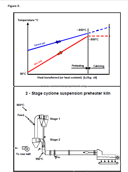
• 2-stage cyclone pre-heater kiln:
∗ Less sensitive to circulating elements than 4-stage pre-heater
∗ Higher heat consumption than pre-heater with more stages
♦ Most recent innovations:
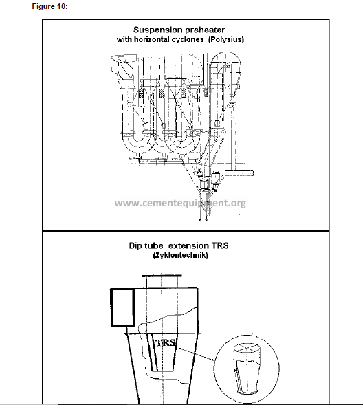
• Horizontal cyclone for “low profile” preheaters (Polysius)
• Dip tube add-on RTS for 30% lower cyclone pressure drop
1. GENERAL
1.1 History
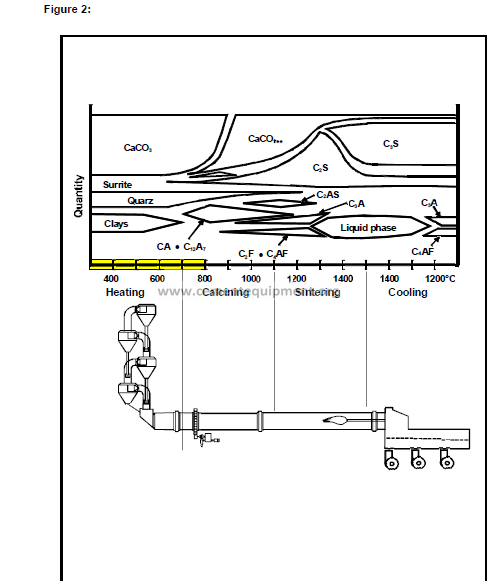
With dry process, the heat exchange for heating up and calcination takes place between hot
kiln gas and dry powder. Since the high dust losses from long dry kilns made it almost
impossible to achieve acceptable heat consumption: other heat exchange principles had to
be applied.
Since the temperature range to be covered is below 1000°C, where the meal behaves
normally like dry powder, stationary reactors where the meal is in suspension with the hot
gas can be used.
The first patent for a suspension preheater using four co-current cyclone stages was applied
for in 1932 and issued in 1934 by the patent office in Prague to a Danish engineer employed
by FLS. Even though the concept was entirely described in the patent, it took another 20
years for industrial application in 1951 by the company Humboldt, now KHD.
Other developments using shaft stages have been abandoned and today, a suspension
preheater is actually a cyclone preheater.
1.2 Trend
All new kiln systems and the majority of the ones with start-up date after 1970 are equipped
with cyclone pre-heaters. Gradually, older plants with wet kilns or long dry kilns are shut
down for good due to their age as well as their high specific production cost
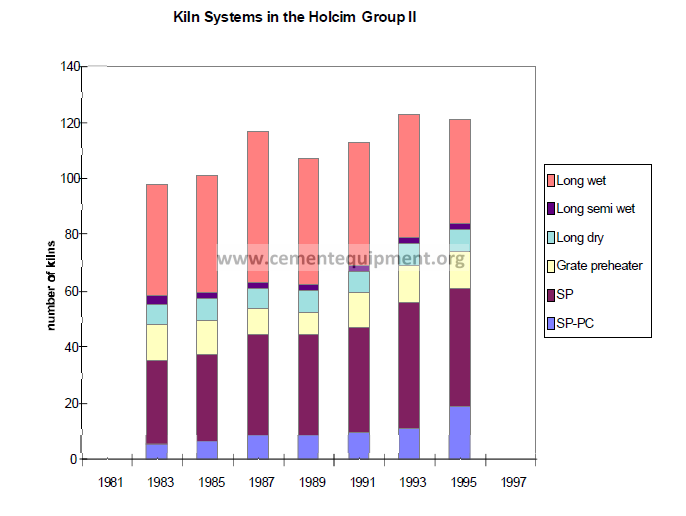
The portion of world’s cement produced with kilns using suspension pre-heaters is still
growing, as can be seen by the development of the Holcim plants. It looks as if it will exceed
95% one day because no feasible alternative solution changing this development is in sight.
In combination with pre-calciners, units of 10’000 t/d have been built using up to four strings,
five stages. Typically, 3500 t/d can be handled in one string, in a recent project even 4000
t/d have been proposed.
2. HEAT EXCHANGE IN A SUSPENSION PREHEATER
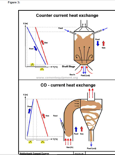
2.1 Counter-Current Heat Exchange (Shaft Stage)
The most efficient type of heat exchange is the counter-current principle. The flows of the
heat releasing media and the heat absorbing media are in opposite directions. This provides
optimum the temperature difference (=temperature gradient, in theory allowing almost
complete heat exchange.
In case of a suspension preheater, where powder is suspended in a gas, the heat exchange
takes place in a “reactor” vessel where the hot gas enters from below and leaves at the top.
The meal to be preheated is fed at the top. The meal retention time depends on distribution
across the gas flow and the retention time, which is determined by the gas velocity.
In industrial installations, the heat exchange proved to be far below expected, because even
distribution of the meal was not achieved, particularly not with large units.
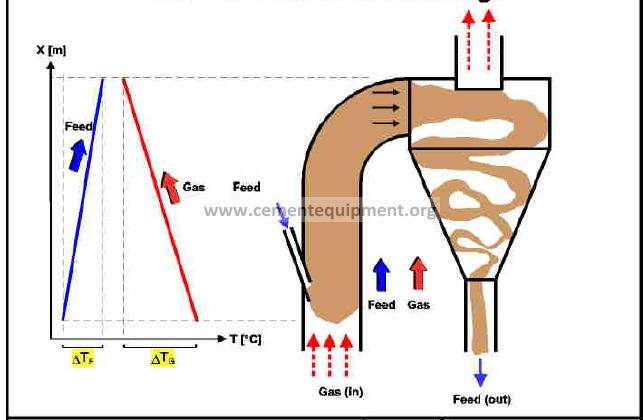
2.2 Co-Current Heat Exchange (Cyclone Stage)
Co-current heat exchange takes place if both heat exchanging media flow in the same
direction. Because of the rapidly decreasing temperature difference, the meal can never
reach gas inlet temperature.
Good and reproducible results in industrial installations with this type lead to the
predominance of this principle in the cement industry. The heat exchanger is a gas duct with
velocities from 10 to 20 m/s, equipped with good meal dispersion devices. The purpose of
the cyclone is primarily to separate meal from gas, and not to exchange heat!
2.3 Thermodynamic Limits
Regardless of the type of heat exchange, there is always a thermodynamic imbalance
between hot gases from kiln and calciner and cold raw meal. The heat contained available in
the hot gas leaving the rotary kiln exceeds the heat required for heating the meal to the
temperature levels required for calcination.
Another limit must be observed: Because the temperature gradient between gas and meal (T
gas > T meal) must always be maintained, a higher calcination degree than 30% cannot be
achieved without additional heat input.
The following heat balance estimate shall illustrate this:
Heat contained in the gas: 2300 kJ/kg cli
(1100°C; 1.3 Nm3/kg cli)
Heat to preheat meal to 850°C: 1300 kJ/kg cli
(1.6 kg meal /kg cli)
Heat required for 30% calcination: 650 kJ/kg cli
Rest (ideal heat exchange): 350 kJ/kg (corresponding to 200 °C)
This shows that even if the heat of the gas above 850°C is used for partial calcination (about
30%), there is still excessive heat in the gas which would correspond to 200°C gas
temperature.
It is obvious that even with a very large number of stages (with accordingly small
temperature gradients), there will always be excess heat! This waste heat is lost only for the
kiln system, but not for the plant, since it can be used for raw material drying in the mill.
3. PREHEATER TYPES
3.1 Preheaters with Shaft Stages
The rather disappointing performance of the shaft stage made it virtually disappear from the
market. Many hybrid preheaters were equipped with one or two cyclone stages replacing the
shaft stage.
Shaft stages at the kiln inlet have the advantage to be less sensitive to build-ups. This could
be an advantage in cases where elevated sulfur input in the kiln system must be expected.
Several Suppliers built preheaters using shaft stages. Two groups can be distinguished:
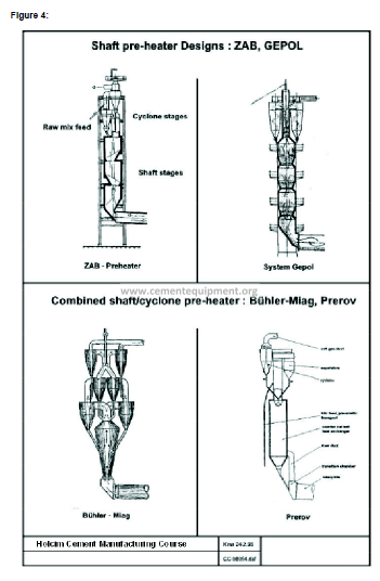
3.1.1 Pure shaft preheaters:
Polysius: • GEPOL
• Self-supporting structure (no tower required)
• Vertical tube with restrictions
• For small capacities (up to ca. 1000 t/d)
ZAB Dessau: • Some applications in Eastern Europe
• Similar to GEPOL, but not self-supporting
• The Deuna plant had originally 4 ZAB shaft preheaters
3.1.2 Hybrid preheaters:
Several suppliers used a combination of shaft and cyclone stages:
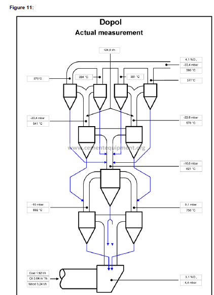
Polysius: • DOPOL preheater (first generation)
• The central swirl-pot (second lowest stage) was shaft stage
• Replaced by DOPOL 90 from 1990
• Gradually developed into a cyclone preheater
• Up to ca. 3000 t/d
Bühler-Miag: • Lowest stage was shaft stage
• Later often replaced by cyclone stage
Prerov: • One large shaft stage with dedusting cyclone
• Shaft stage selfsupporting
• Additional cyclone stage possible
• Separate meal duct to kiln
• As sensitive to circulation phenomena as a cyclone type
MBM: • Bottom shaft stage with 4 cyclone stages
• Only hybrid design still on the market
3.2 Preheaters with Cyclone Stages
A quasi counter-current heat exchange can be achieved by serial installation of several cocurrent
stages. The result is the multi-stage cyclone preheater as it is generally applied in
modern cement plants.
In the early years, one and two stage systems have been installed with long kilns, often to
avoid problems caused by circulating phenomena. A large number of plants are equipped
with four stages; the majority of them were built before 1990.
Today, five stage preheaters represent the economical optimum. High raw material moisture
leads occasionally to fewer stages, in combination with low temperature dedusting systems,
or in areas with high fuel cost, six stages can be more economical. Number of stages
depends thus on:
♦ Raw material moisture (i.e. drying heat requirement)
♦ Cost of thermal energy
♦ Cost of electrical energy
♦ Gas handling system (temperature limit, dew point)
♦ Soil conditions (foundations, earthquake zone -> height of structure)
If raw material moisture shows significant seasonal variations, it can be economical to equip
preheaters with “variable stages”. This is achieved by feeding all or part of the meal to the
second highest stage or by skipping a stage.
Note: Numbering of stages is always from top to bottom: top stage = stage 1.
Exception: Polysius: bottom stage = stage 1
3.3 Economical Number of Stages for Cyclone Preheaters
For many years, the pressure drop across one preheater stage was up to 1,5 kPa (15 mbar).
The reason for the 4-stage pre-heater being so widely used is, that it represented an
optimum between investment cost (structure height, foundation), pressure drop and heat
consumption. . The performance of comparable systems built in about the same period are
within a relatively narrow range.
About two third of the pressure drop of a stage occurs in the cyclone and depends on its
shape/design and the size, the latter being the determining cost factor.
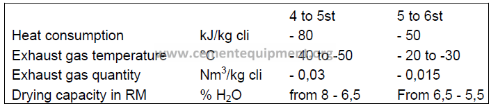
New cyclone designs are now on the market with only 0,5 to 1,0 kPa (5-10 mbar) pressure
drop per stage. Considering increasing energy cost, it is justified to install 5 or 6 pre-heater
stages for new or modified kiln systems.
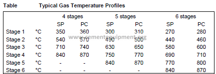
The following table indicated the estimated effect of a 5th and a 6th cyclone stage:
3.4 Minimum Gas Velocity
Dimensioning of a cyclone preheater is a careful consideration of the importance of
separation efficiency, pressure drop, part load operation capability, size of the preheater and
cost of the project.
It must be mentioned that there is a lowest gas velocity in a cyclone preheater. If operation
results in lower figures, the meal will not be lifted by the gas anymore, resulting in poor heat
exchange and consequently high heat consumption, but also excessive temperatures .
Large dimensions give lower velocities with low pressure drop, but also limit the lowest
possible economical production.

4. DESIGN FEATURES OF PREHEATER-CYCLONES
4.1 General
Modern preheaters are designed for low pressure drop using the new cyclone design which
must still provide good separation efficiency, particularly in the top and the bottom stage.
Cyclone inlet velocities are designed in the range of 10 to 15 m/s.
It has been found that the total pressure drop of one cyclone stage is caused by about 1/3
by the gas duct (i.e. lifting of the meal) and 2/3 by the cyclone. Since not much can be done
regarding lifting of the meal, efforts have been made to improve the cyclone design in order
to reduce total pressure drop: the low pressure (drop) cyclone was designed.
Cyclone design means to optimize between high separation efficiency, low pressure drop
and low cost (i.e. small size).
Other than having the correct design parameters, all stages should be equipped with
♦ Dip Tubes (also called ‘immersion tubes’, ‘thimbles’ or ‘vortex finders’)
♦ Meal flaps
♦ Splash boxes (or splash plates).
4.2 Dust Cycles
The entire kiln system is subject to dust cycles. Precondition is gas flow in opposite direction
of pulverized process materials. This causes wear, unnecessary material transport and heat
losses due to heat exchange in the wrong direction.
In the preheater, internal dust cycles due to poor separation efficiency of the cyclones result
in less than optimum preheating of meal. Unfortunately, it is almost impossible to measure
dust loss from lower cyclones in normal operation. The only indicator is the temperature
profiles of gas and meal, but even the meal temperature is not always easy tp measure.
4.3 Features
4.3.1 Splash Box
Early cyclone preheater designs had no splash boxes. Instead, the meal was fed into the
gas at a higher point against the gas flow, creating some turbulence with a certain
distribution effect.
Modern cyclone preheaters must be equipped with correctly designed splash boxes for
optimum meal distribution across the gas duct cross section. The principle is based on
impact on a plate. In some installations, the bottom plate of the splash box can be adjusted.
Note: No splash box must be installed at the kiln inlet! The hot meal from the bottom cyclone
must enter the rotary kiln as smoothly as possible. Meal is easily picked up by the kiln gas
and will create a dusty transition chamber.
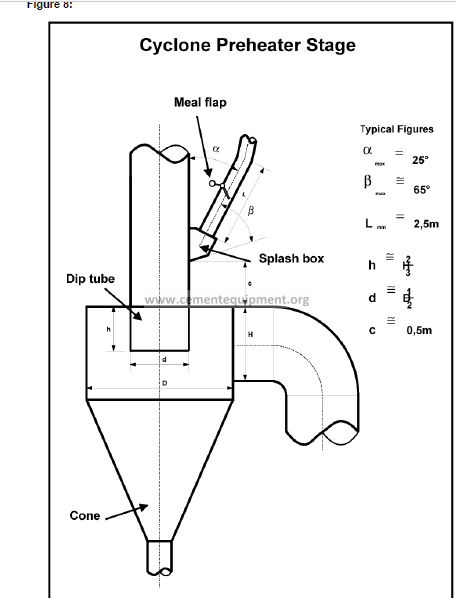
4.3.2 Dip Tube (Immersion Tube, Vortex Finder, Thimble)
This integral element of the cyclone has a decisive influence on separation and pressure
drop. It makes the gas to follow a 180 to 360° rotation thus creating the desired centrifugal
force for the separation effect.
In the colder upper stages (stage 1 to 3) it can be designed as simple extension of the outlet
gas duct, made from steel plate. These upper stage dip tubes create usually no problems
except when the preheater gets overheated, e.g. during start-up. Then, the dip tube can
collapse, causing excessive pressure drop.
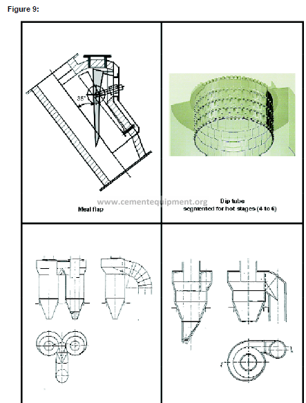
In the hotter lower stages, mild steel ducts from one piece are not suitable. Several
segmented designs made from heat resistant steel or ceramic material (Hasle) are available
on the market. It is standard today that all stages are equipped with dip tubes.
Note: It appears that some designs of segmented dip tubes have a tendency to unhook
enabling individual elements to drop and to block the cyclone outlet!
For older plants, installing a segmented dip tube in the lower stages is a optimization
possibility which is often applied.
4.3.3 Meal Flap
In order to understand the purpose of the meal flap, the following two aspects must be
mentioned:
♦ There is a pressure difference across a cyclone stage, i.e. between two subsequent
cyclone gas outlets (maintained by the ID fan).
♦ Without meal, there are two ways the gas can flow from one stage to the next: through
gas duct and through meal duct
If there was an ideal kiln system, i.e. a system with 100% constant meal flow and never
changing operation parameters, the meal duct diameter could be designed for just the meal.
The meal would then fill the entire cross section, leaving no opening for the gas. In reality,
there are fluctuations of meal and dropping build-ups, requiring oversized meal ducts.
It is the purpose of the meal flap to close the free cross section not used by the meal, to
avoid gas bypass. There are designs that open only when a certain weight pushes them
open, thus creating meal fluctuations. Other designs (see figure) are adjustable so that they
move only in case of meal peaks or lumps.
Not operational meal flaps cause heat loss and allow build-up formation in meal ducts
(circulating elements)!
4.3.4 Cyclone Shapes
The separation efficiency of a cyclone gets better with longer dip tube and increasing
distance between swirl (cylinder) and dust collecting cone, i.e. with high and slim shapes.
The top stage of preheaters is designed for high separation efficiency. In order to save
height, most suppliers install twin cyclones with the drawback that meal and gas have to be
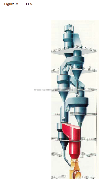
split. There are a few plants from FLS with only one top cyclone, avoiding this drawback.
5. PREHEATER OPERATION
The performance of a preheater is assessed based on the criteria:
♦ Temperature profile (first indicator: exit gas temperature)
♦ Pressure profile
♦ Oxygen profile
5.1 Operating Problems of Suspension Preheaters
Some reasons for poor preheater performance frequently experienced:
♦ Worn out or non existing immersion tubes (often in bottom stage)
♦ Open inspection doors, leaky gaskets or holes in the pre-heater (cold false air leaks in,
can be detected by hissing sound)
♦ Blocked or non existing meal flaps
♦ No splash boxes (specially older preheaters), combined with not optimum position of
meal feed point (e.g. old DOPOL)
♦ Excessive dust circulation due to poor separation efficiency of cyclones
5.1.1 Circulation Phenomena.
Cyclone preheaters are sensitive to circulation phenomena. Cyclone blockages cause kiln
stops resulting in production loss and dangerous cleaning actions. Possible causes are:
♦ Excessive input via feed or fuel (Cl, S, 1 Na, K)
♦ Chemical unbalance (sulphur, alkali ratio)
♦ Unfavourable kiln/burner operation
♦ Unfavourable design geometry of bottom stage and kiln gas riser duct area
Countermeasures known today allow to solve the problems are:
♦ Change feed composition or fuel quality
♦ Improve burning conditions
♦ Install automatic cleaning (air cannon, big blasters) at critical locations
♦ Change temperature profile by installing a small secondary burner
♦ Install a kiln gas bypass* system
*A bypass system is not desirable since it is expensive and causes loss of heat and material.
It is therefore the last solution left and should be only considered if all other measures are
not sufficient.
The paper ‘circulating phenomena’ contains more details on this rather complex subject.
6. NEW DEVELOPMENTS
6.1 Horizontal Cyclone
Polysius have developed a “horizontal cyclone”. (not to be mixed up with earlier designs of
Kawasaki!)
This cyclone is a modified version of the conventional cyclone with the major difference that
the gas outlet is also at the bottom, encircling the meal outlet.
The heat exchanger duct is still from bottom to top, but the stages can be arranged next to
each other instead on top of each other. This allows a significantly lower height of the
preheater structure.
It is expected that savings in civil cost can be achieved. Additional benefit is possible in
cases where the maximum height is restricted (earthquake zones, scenery protection).
Only top cyclones on conventional preheaters are in industrial operation, however. Any other
experience is yet to be made.
6.2 TRS
The Austrian company Zyklontechnik have introduced a dip tube add-on device which will
reduce pressure drop across the cyclone (not the entire stage!) by 30% at otherwise
unchanged performance.
The principle is to avoid the flow around the edge of the dip tube. Instead, the horizontal
swirl from the gas inlet is maintained and can continue into the dip tube through an
accurately shaped slot in the TRS.
Prerequisite is aerodynamically correct cyclone design and very accurate manufacturing of
the TRS, which cannot be made locally.
The device can be mounted to the bottom of a shortened dip tube. If the inspection opening
is large enough, the whole unit can be installed in one piece, otherwise it comes in pieces.
Several TRS are in operation (not in preheaters, however) with performance equal to or
exceeding the predicted figures.