Contents
CRUSHING in Cement Industry
[wpecpp name=”package + Updates forever” price=”250″ align=”center”]
3.1 Principles of crushing
The raw materials are quarried in lump size up to 1- 2 m and must be reduced to less
than 0.2 mm. This reduction is carried out in two stages, crushing down to 25 mm.
because the mill is designed for a feed of that maximum size- and subsequent
grinding. Raw materials occur in widely varying forms and a large range of crusher
types is available. Comminution, i.e. the process of fragmenting materials, can be
effected according to three different principles:
Impact: (hammer crusher, drier- crusher)
Compression: (jaw crusher, cone crusher)
Shearing: (roll-jaw crusher, roller crusher)
The relationship between feed size and exit size of the material is termed the
reduction factor. Crushers with high reduction factors like hammer crushers can
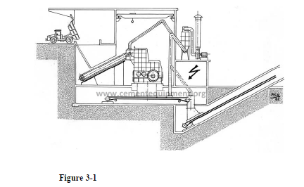
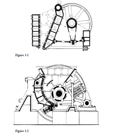
crush to the required size in one stage. The installation is shown in figure 3.1. The
material is delivered from the quarry, usually by dumpers, and tipped into reinforced
inlet chute whose bottom is a lamellated conveyor feeding the crusher.
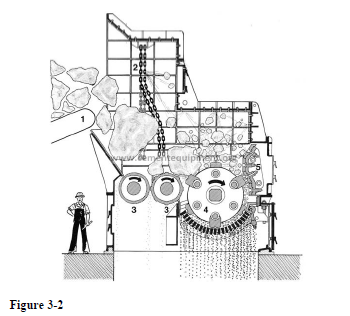
The remaining crusher types are used for very hard and abrasive, respectively soft
and sticky materials. They all have low reduction factors and in the cement factory
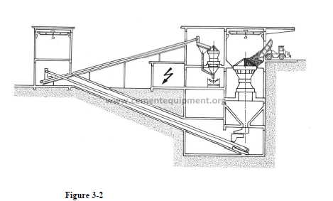
they are normally operated in multi-stage crushing. Figure 3.2 illustrates a two-stage
crusher installation with cone crushers. After the first stage the fine fraction of pre
crushed material is removed on a vibrating screen and added to the coarse fraction
which is finish crush in a smaller secondary cone crusher.
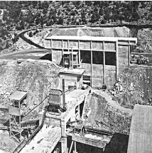
The photo depicts a crusher installation. Note the dedusting filters and the transport
conveyor to the raw material store.
3.2 Hammer crushers
Hammer crushers are impact crushers, fragmenting taking place between a set of
rotating hammers and a fixed crusher plate. The rotating unit consists of a shaft with
arms from the extreme ends of which the hammers are pivotally mounted. A big
flywheel adds to the crushing momentum.
Hammer crushers are suited for crushing of hard, non-abrasive material with little or
no moisture, and they can crush stones of lump size exceeding 1 m down to 25mm.
with power consumption 0.5 to 1 kWh per ton of crushed stone.
The outlet grate is designed as one detachable unit consisting of triangular grate bars,
fitted between two parallel cheeks. The width of the slots is determined during the
dimensioning. The larger the width the coarser is the crushed stone and the higher the
output for the same power consumption. The grate unit is adjustable in relation to the
rotor in order to compensate for wear.
The rotor is assembled and may be dismantled as one unit.
The grates and hammers are exposed to wear up to 10 g per ton of crushed stone.
FLS hammer crushers are designed in the following types:
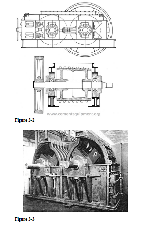
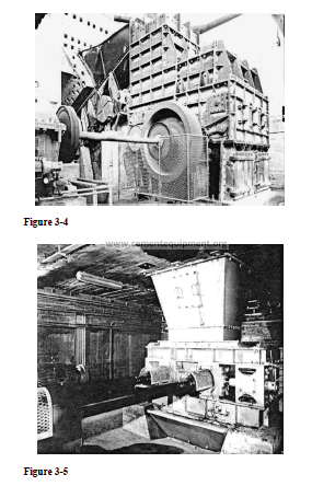
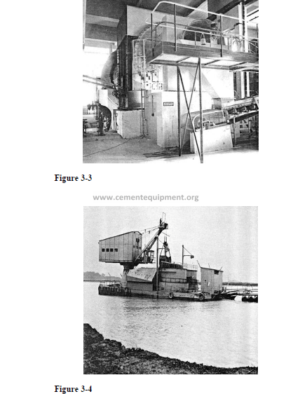
Slow-speed hammer crushers with inlet grate for primary crushing. The grate
protects the crusher against overloading from oversized stones. The crusher is
available with single rotor, type EMI, figure 3.4 and with double rotor, type DMI,
figure 3.13.
A sheer pin secures the flywheel. In case it fractures due to overloading, the wheel
will run loose on the shaft and activate a micro switch which stops the feed and
crusher motor simultaneously.
Double hammer crushers can crush up to 300 t/h limestone with a power
consumption of approximately 330 kW and 25 mm slots in the outlet grate.
High-speed hammer crushers without inlet grate for secondary crushing. The
grate is omitted since the material is already pre-crushed. The high-speed hammer
crusher is manufactured both with a single rotor, type EUI, figure 3.5 and with
double rotor, type DUI, figure 3.6.
The type designations are followed by two sets of digits showing the diameter across
the hammers and the width of the rotor, e.g. DMI 200 x 180.
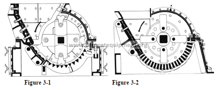
3.3 The EV-crusher
The crusher is capable of crushing rocks from a lump size of 2.5 m down to 25 mm
in one stage, with throughputs up to 1300 tph. It is well suited for hard, not
exceedingly abrasive material with a certain proportion of sticky components.
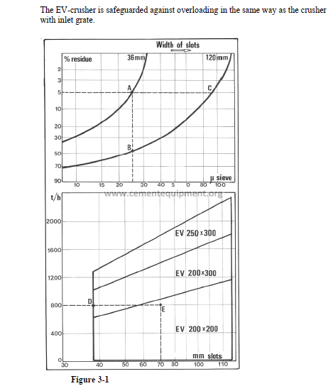
The materials are fed to the crusher by a lamellated feed conveyor, and a heavy chain
curtain suspended across the inlet opening guards against lumps being hurled
backwards again. The materials fall down onto two shock-absorbing rollers with
differing speeds to prevent wedging of the rocks. The fines are separated off between
these, and the coarse fraction is fragmented by the hammers and passes through the
slots between the outlet grate bars.
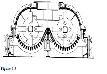
The outlet grate is of a similar design to the hammer crusher grate. A fineness of 5%
+ 25 mm is obtained with 36 mm slots, as seen in figure 3.7, position A. increase in
the slot width to 120 mm produces a coarser product of 50% + 25 mm (B) or 5% +
90 mm (C).
From the diagram of the crusher sizes it will be evident that selection of size depends
both on production and fitness, i.e. the width of the slots in the outlet grate. Width for
example 800 t/h and 50 mm slots crusher EV 200 x 300 is required whereas a size
smaller could be employed with 70 mm slots.
3.4 The jaw crusher
The jaw crusher, also named the Blake crusher after its inventor in 1858, figure 3.9,
is a typical compression crusher, suited for fragmenting hard and abrasive rock. It
has a reduction factor and is used in multi-stage crushing, usually as the primary
crusher.
Fragmentation takes place between a fixed and a movable jaw, the latter hinged at
the top from a shaft mounted in journals on the frame. The jaw is moved back and
forth with a chewing motion through a toggle-joint link, when the crank moves up
and down the connecting rod.
Large jaw crushers can crush stones up to 1.5 m lump size and weighing 9 tons. The
power consumption is around 0.2 – 0.5 kWh/t and FLS crushers are made for
outputs up to 1000 t/h .
The crusher size is given by the dimensions of the inlet opening, e.g. 1900 x 1500.
3.5 The roll-jaw crusher
This crusher type, figure 3.10, is used for soft, sticky materials containing some
moisture. A hard fraction is necessary to clean the teeth. Here the crushing takes
place between a fixed, curved jaw and a roller with teeth, which tear the stones to
pieces. The jaw is suspended at the top and held at the bottom by heavy springs,
which will resile when the crusher is fed over size material and un-crushable
material.
Roll-jaw crushers are also used for crushing raw coal and gypsum. When crushing
raw materials this type is normally only suited for multi-stage crushing due to the
low reduction factor.
The crusher size is given by the diameter and the width of the roller, f.ex. 1200 x
1600.
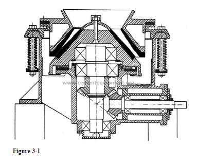
3.6 The cone crusher
The cone crusher, are the gyratory crusher, figure 3.11, is not manufactured by FLS
but is sometimes preferred for large productions of hard, abrasive material. The
crusher is a compression crusher, very wear resistant but with a low reduction factor.
Crushing takes place between a stationary and a moving cone, the latter revolving on
an eccentric axis in relation to the fixed cone. The design causes a constantly varying
cross section of the inlet opening which so to speak chews the passing material.
The capacity of the cone crusher is usually so large that the feeder can be omitted
and the feed tipped directly into the crusher. Cone crushers are designed in many
versions and sizes, both for primary and for secondary crushing.
3.7 The roller crusher
This crusher type, shown in figure 3.12, is used for comminution of soft, sticky and
moisture materials with a hard fraction embedded. It works mainly from the principle
of shearing, the material being torn between two rollers fitted with teeth. The hard
fraction serves to clean the teeth.
The roller crusher has a low reduction factor and is nearly always used as a
secondary crusher, for example after a roll-jaw crusher.
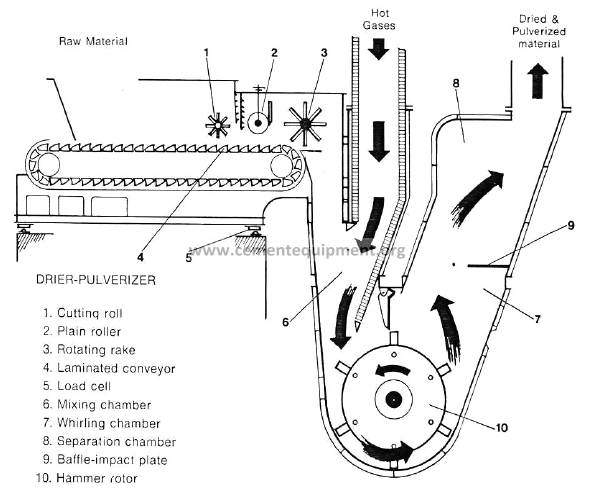
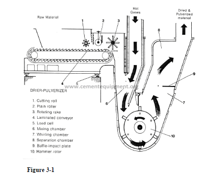
3.8 The drier-pulveriser
Hammer crusher dryers are drier-pulverisers, particularly designed for crushing and
drying, in one stage, sticky, non-abrasive raw materials, such as chalk, clay and
slurry filter cake. The FLS hammer crusher drier is designed to handle materials with
water content of 10-30%.
The materials are fed into the hammer crusher drier by an FLS lamellated box feeder.
The hammer is provided with a closed bottom part and is continuously swept by a
stream of hot air with inlet temperatures from about 5000 C to 8000 C, which predries
the materials in the mixing chamber. Additional drying is effected when the
material passes the hammers and into the whirling chamber.
The hammers effect crushing of the 100-150 mm lumps, by mutual collisions, and by
impact on the baffle elements. The circumferential velocity of the hammer tips is 25-
30 m/s.
After passing the hammers, most of the materials has been crushed down to suitable
fineness and is swept away by the air. In the separation chamber the coarser grains
falls back on the hammers for further pulverisation.
The hammer crusher drier is normally adjusted so that the finished material has a
residue of a few percent on the 1 mm sieve and a water content 1-3%.
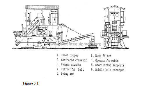
3.9 Mobile crusher installations
Mobile crusher installations are occasionally used. Such installations are placed
directly in the quarry and follow the quarry machinery. Common crusher types are
the impact crusher and the jaw crusher which at the quarry are used for primary
crushing, for example down to 100-50 mm lump size. Figure 3.17, shows a typical
mobile crusher installation.
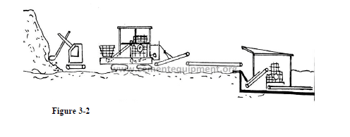
The mobile crusher installation makes it possible to pre-crush the raw materials
immediately at the quarry site and consequently to transport them by conveyor belt to
the finishing crusher, thus saving heavy transport. The principle of combined quarry
and crushing operation is illustrated below.
Figure 3-
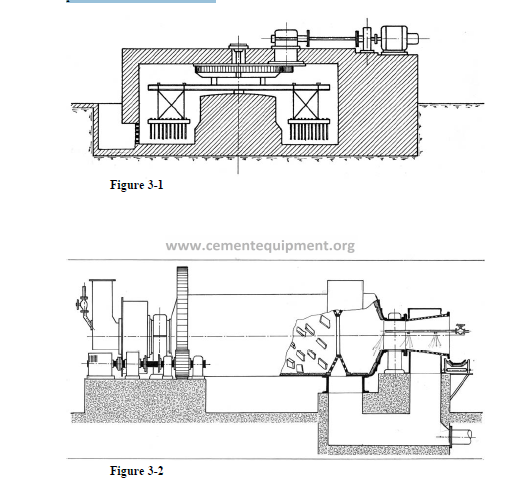
3.10 Washing
Soft raw materials like chalk and clay are washable, i.e. they will dissolve into coarse
slurry when mixed with water and stirred. Washing maybe done in a wash mill,
figure 3.19. the wash mill is a circular concrete basin with a centre pillar carrying a
stirring device of chains and harrows. Water and material is fed to the wash mill and
the slurry is discharged through peripheral grates in the basin wall into the pump
sump. The wash mill is stopped at intervals and cleaned for accumulated stones.
The wash drum, figure 3.20, is a modern version of the wash mill. It is a onechamber
mill without grinding media but with built-in lifters on the internal lining
plates. The drum is fitted with peripheral outlet grates near the outlet.
The material, which may be chalk or clay or a mixture of both is fed to the drum and
water added. The slurry leaves the drum through the grates, passes a screen for
removal of nibs and flows down into a sump. From here the slurry is pumped to a
raw-slurry basin or a finishing mill.
Accumulated stones and unwashable debris overflow through the open-ended
trunnion at the outlet. Wash drum slurry normally contains 36-44% water and has a
particle size less than 2-3 mm.
3.11 Selection of crushing machinery
The table should be guidance to the selection of crushers for cement raw materials.
There are, however, many variations of constellations due to individual requirements