Quick answer
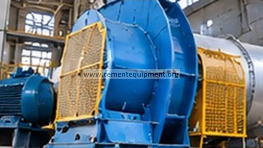
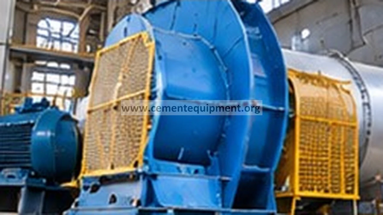
A clinker-cooler fan can surge when high bed resistance pushes the operating point toward an unstable region of the fan curve. Diagnose the fan and cooler together using inlet/damper position, airflow, compartment pressure, motor current, fan vibration/noise, bed depth and grate condition. The correction may be in material distribution or cooler resistance rather than in the fan itself.
Problem / job
Cooling-air flow and pressure oscillate, the fan sounds unstable, or current fluctuates when bed resistance is high.
Evidence
Capture fan current/speed, damper position, airflow if measured, undergrate pressure, bed depth, clinker distribution and surge timing.
Decision
Separate fan operating-point instability from damper/control hunting, dense bed, blocked grate, duct restriction and measurement error.
As-found evidence capture
Trend fan pressure, airflow where available, motor current, speed, damper position and cooler compartment pressure while the oscillation is present. Note clinker-bed depth and whether the event appears only at high kiln feed or after a bed-distribution upset.
Listen for cyclic aerodynamic noise and compare neighboring cooler fans. A pressure oscillation without corresponding motor or airflow behavior may be an instrument problem rather than true surge.
Field sequence before changing fan control
- Trend fan pressure, airflow if reliable, motor current, speed and damper position through the unstable event.
- Add cooler undergrate/compartment pressure, grate speed, kiln feed and bed-depth observations to the same timeline.
- Verify the pressure and airflow measurements before diagnosing aerodynamic surge.
- Compare the affected fan with adjacent cooler fans at similar bed conditions.
- Inspect grate restriction, fines accumulation and bed distribution before retuning the damper or VFD loop.
- Use the installed fan curve at actual speed/density to check whether the operating point approaches the unstable low-flow region.
- Correct the initiating resistance/control cause, then repeat the same high-bed condition and prove stable fan operation.
Go/no-go rule: do not tune the fan loop around a blocked grate or excessive bed resistance. Restore the process resistance first if it is the initiating event.
Seven-step diagnostic workflow
1. Confirm a real fan instability
Correlate pressure pulses with current, airflow and sound/vibration. Verify transmitters before changing fan controls.
2. Check the operating point
Compare the current pressure/flow condition with the fan’s approved operating envelope. High system resistance can force a fan toward unstable low-flow operation. Use the manufacturer curve, not generic assumptions.
3. Inspect bed resistance
Check clinker bed depth, distribution and size segregation. Dense local regions or excess bed depth raise pressure demand and can destabilize one fan compartment.
4. Inspect grate and compartment restriction
Blocked or damaged grate plates, accumulated fines and duct restrictions can increase resistance. Compare compartment pressure and fan load across the cooler width.
5. Review damper and VFD control
Check whether damper or speed control is hunting in response to the pressure oscillation. A control loop may amplify an aerodynamic problem or create instability of its own.
6. Check inlet and fan mechanical condition
Inspect inlet filters/screens where applicable, inlet vanes, casing condition and vibration. Mechanical damage or inlet distortion can reduce stable fan performance.
7. Prove the correction at the former high-resistance condition
After correcting bed distribution, restriction or control issues, run at representative load and confirm stable pressure, current and airflow without surge noise.
Evidence-to-decision table
| Evidence | Likely direction | Next check |
|---|---|---|
| Pressure/current/airflow oscillate together | Real aerodynamic instability | Fan operating point and system resistance |
| Only pressure signal oscillates | Instrument/impulse problem | Pressure measurement |
| Event appears with deep/dense bed | Cooler resistance too high | Bed depth, distribution, grate |
| Damper command oscillates strongly | Control interaction | Damper/VFD loop after process checks |
| One fan unstable, neighbors normal | Local compartment/fan issue | Grate, duct and fan condition |
Field measurement sequence before any control adjustment
Build one synchronized trend covering fan speed, damper or inlet-vane position, motor current, undergrate pressure and measured airflow if the instrument is trustworthy. Add kiln feed, cooler grate speed and bed-depth observations on the same timeline. The objective is to identify which variable moves first. If bed resistance rises first and airflow collapses before the controller reacts, treat the cooler/process resistance as the initiating event. If damper or VFD demand oscillates first while bed conditions remain stable, investigate control interaction, feedback quality and actuator response.
Compare the affected fan with the adjacent fan serving a similar cooler zone. A local high-pressure/low-flow pattern points toward compartment restriction, plate blockage, air-distribution problems or a fan-specific inlet condition. If several fans become unstable together during a high-bed event, investigate system-wide clinker distribution, bed depth and grate loading rather than tuning each fan separately.
Separate aerodynamic surge from control hunting
True aerodynamic instability normally produces a coupled pattern: pressure and airflow fluctuate together and may be accompanied by cyclic noise, vibration or motor-current movement. Control hunting can mimic this pattern, but the command signal often leads the process response. Review actuator travel, feedback lag, deadband and any recent changes to pressure or airflow setpoints. Verify pressure transmitters and impulse lines before retuning a loop; a noisy or partially blocked pressure signal can make a healthy fan appear unstable.
When reviewing the fan curve, use the installed fan’s manufacturer data at the actual speed and gas density conditions. Do not apply a generic surge margin or copy a neighboring fan’s setpoint. The safe correction is the one that restores a stable operating point while maintaining the cooling-air requirement and acceptable cooler performance.
Return-to-service acceptance criteria
Accept the correction when the fan operates stably at representative bed resistance, pressure and current no longer oscillate abnormally, airflow remains adequate, cooler bed distribution is controlled and the operating point stays inside the approved fan envelope.
After the correction, preserve a short synchronized trend showing fan command, pressure, airflow or current, cooler load and bed condition. This becomes the baseline for the next high-resistance event and helps distinguish a genuine recurrence from normal operating movement. If instability returns only after the bed reaches the same resistance pattern, investigate why that resistance recurs instead of repeatedly retuning the fan loop.
Common mistakes
Do not simply close or open the damper repeatedly without checking the fan curve. Do not blame the fan if the cooler bed is excessively resistant. Do not tune the control loop around blocked grate plates. Do not rely on one pressure transmitter. Finally, fan surge can be mechanically damaging, so prolonged operation in an unstable region should be avoided according to plant/OEM procedures.
Related Infinity guides
Build a stronger cement maintenance library
The Infinity for Cement Organization technical package contains 900+ technical files for cement professionals. It is a one-time $249.99 purchase, with instant download immediately after payment and lifetime updates forever at no additional cost.