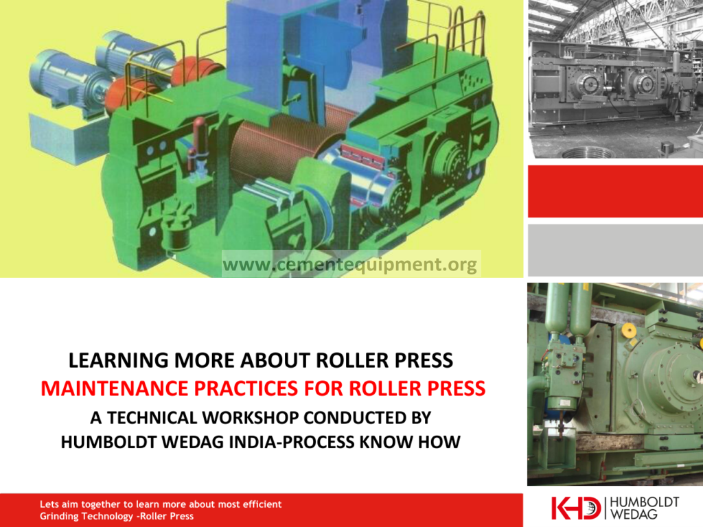

What “Skew” Means in a Cement Roller Press
In a roller press, the fixed roll and floating roll compress a bed of material. Ideally, the operating gap is reasonably balanced from one side of the roll width to the other. Skew describes a difference between the two side gaps, so the floating roll is no longer close to parallel with the fixed roll.
A small dynamic difference can occur because the feed bed is never perfectly uniform. The engineering objective is not to force the machine into a rigid geometric condition. It is to keep the floating roll controlled, protect the hydraulic and mechanical system, and prevent persistent skew from becoming a symptom of poor feed distribution, unstable grinding pressure or abnormal machine condition.
How the Skew-Control Feedback Loop Works
Modern hydraulic roller presses can monitor the roll position on both sides and use the hydraulic system to react when the gap difference moves outside the permitted control band. Current FLSmidth HRP documentation, for example, describes Advanced Skew Control using hydraulic pumping to the cylinders with LVDT position feedback. As skew starts, the control system changes the press force applied to the hydraulic cylinders so the rolls remain as close to parallel as practical while accommodating real feed variation.
Why Feed Distribution Matters as Much as Hydraulics
A skew-control system is not a substitute for a well-distributed material column. If one side of the roller receives a different amount, size distribution, moisture condition or bed density than the other, the floating roll sees different resistance across its width. The control system can respond, but repeated large corrections point back toward the process.
This is why roller-press operation should be reviewed as one system: feed gate or chute geometry, material segregation, recirculating load, hydraulic pressures, left/right gap, motor power, vibration and cake condition. Looking only at hydraulic pressure can produce the wrong conclusion.
Creates unequal bed resistance across the roll width and can drive a persistent gap difference.
Left/right position measurement identifies the direction and magnitude of skew.
The control system modifies cylinder pressure according to its machine-specific correction logic.
If skew repeatedly returns, inspect feed distribution, chute condition, material properties and mechanical condition.
Signals That Should Be Viewed Together
| Signal | What it tells you | Why it matters |
|---|---|---|
| Left/right roll gap | Direct indication of skew direction and magnitude | Primary position feedback for skew control |
| Hydraulic pressure by side | How the system is applying grinding force | Shows whether correction is balanced or one side is repeatedly working harder |
| Motor power/current | Mechanical load absorbed by each drive | Useful for identifying unequal loading across the press |
| Feed rate and distribution | Whether material is entering the roll width uniformly | Persistent asymmetry often originates upstream |
| Vibration / operating stability | Whether the press is running smoothly under the current bed condition | Confirms whether a skew correction actually improved operation |
A Practical Operator Review Sequence
- Confirm the gap sensors are healthy and the left/right readings are credible.
- Trend skew together with hydraulic pressure on both sides, not as a standalone alarm.
- Compare the two drive loads and note whether skew coincides with unequal motor loading.
- Check feed distribution across the roll width, especially after changes in feed gate position, recirculating load, moisture or particle-size distribution.
- Inspect whether the skew-control system is repeatedly correcting in the same direction. Repeated one-sided correction usually deserves a process or mechanical investigation.
- Verify cake formation, vibration and press stability after any operating change.
- Use the OEM control limits and protection logic for any decision involving pressure setpoints, allowable gap difference, trip limits or manual override.
What Good Skew Control Looks Like
Good control does not mean the two gap signals never differ. It means the machine reacts predictably, the gap difference remains within the OEM-defined operating envelope, hydraulic corrections are not continuously fighting the process, and the press runs with stable feed, acceptable vibration and balanced drive loading.
If the skew-control loop is busy all the time, the better question is often not “how do we increase hydraulic correction?” but “what is making one side of the bed behave differently?” That shift in thinking prevents the control system from masking a feed-distribution or mechanical problem.
Frequently Asked Questions
Is roller press skew always a mechanical fault?
No. Uneven material distribution, bed density, moisture or particle-size segregation can create different resistance across the roll width. Mechanical and hydraulic causes still need to be checked when the pattern persists.
Why are LVDTs used in skew control?
They provide accurate position feedback for the floating roll. The controller can compare both sides and determine the gap difference before applying the OEM-defined hydraulic correction.
Should both hydraulic pressures always be identical?
Not necessarily. Dynamic control may create a temporary difference as the system reacts to feed and roll position. What matters is whether the behavior is normal for that machine and remains inside its OEM operating logic.
What should be checked when skew repeatedly returns?
Check sensor credibility, feed distribution, gate/chute condition, left/right drive loading, material segregation, hydraulic response, vibration and mechanical condition. Persistent one-sided correction should not be treated as a normal steady state without investigation.
Engineering References
This article was cross-checked against current OEM material rather than generic web summaries.
Final Takeaway
Roller press skew control is a feedback problem and a feed-distribution problem at the same time. Position sensors show what the floating roll is doing, the hydraulic system provides the corrective force, and the process determines how hard the control loop must work. The most stable operation comes from treating all three as one system and using the machine-specific OEM limits as the final authority.