Contents
CLICK HERE TO DOWNLOAD EXCEL SHEETS , BOOKS , MANUALS , OPERATION MANUALS , REFERENCE BOOKS , PROCESS BOOKS
The mill shell Optimum dimensions
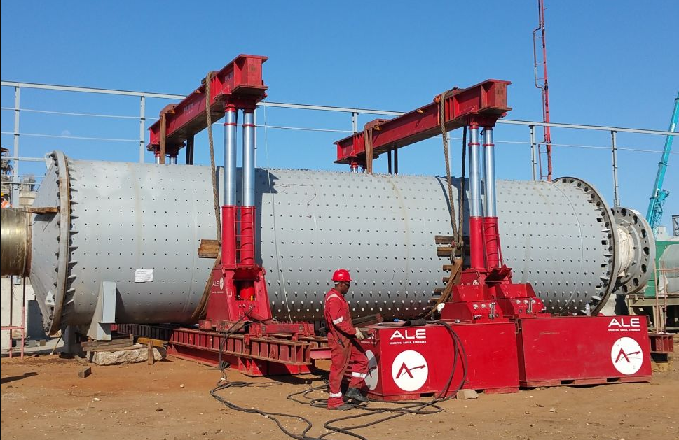
For a fixed capacity the mill tube should have a mini mum weight; only then is the mill shell sized prop erly. To insure the stability of the mill tube, the requirement for minimum weight is compatible with the requirement for the smallest possible surface area of the mill tube. For this circumstance Bernutat [92] has developed an equation from which the minimum weight of the mill results out of a predetermined length to diameter ratio of the mill; that ratio also leads to a minimum required mill lining. For a one compartment mill this ratio is
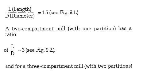
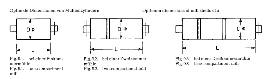
However, for optimum mill sizing, these ratios of length to diameter must be compatible with grinding requirements.
This item requires two basic considerations.
- Holding the mill length constant, the increase of mill diameter provides:
Higher power efficiency
Less floor space per unit of capacity Fewer subrnicron particles in mill product More oversize tramp particles
Lower steel wear rates per ton of product.
- Holding the mill diameter constat, the greater mill length provides:
Lower capital cost per installed horsepower
Fewer oversize tramp particles More micron fines in mill product Lower power efficiency
Opportunity for partitioning the mill cylinder
Thickness of the mill shell
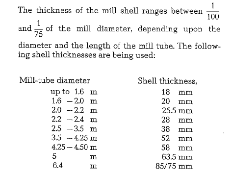
Here, it should be mentioned that the shell thickness depends not only on the diameter, but also on the length of the mill cylinder. Besides, the shell thicknessess of long mills are graded, i. e. the shell thickness increases from both ends toward the mill center.
Mill shell- Standards
In Germany, basic dimensions of tube mills are standardized (German Standards DIN 24111 -Tube mills) [94]. This applies particularly to the inner diameters of the mill cylinders, where gradations are in steps of 200 mm; to the size and arrangement of manholes; to the allocation of the bolt holes for the mill liners; and also to the thickness and radius of the liners.
When calculating the thickness of the mill shell, it should be considered that the bolt holes for the mill liners, allocated according to German Standards DIN 24111. reduce the strength of the shell by about 11 %.
The mill shell is manufactured from steel sheets, Grade MRSt 37- 2 (German Standards DIN 17100, material No. 1.0112.6)*, or from fine-grained structural steel. (German Standards DIN 4102). Boiler plates are also frequently in use, despite the fact that some of their properties, such as e. g. high temperature resist ance, are not consistent with tube mill requirements.
Fine grained structural steel has all the properties required for a mill shell; it is also easy to weld. It is resistant against crack formation and fatigue.
The high strength properties of fine grained struc tural steel, allow savings in the total weight of the mill shell. For example the weight of a mill shell 3.8 x 14m, is roughly 80 tons. The same size mill shell made from FR 50 – steel (manufacturer: Mannes mann-Werke, Germany), weighs only 63 metric tons.
Mill heads
Mill heads are presently manufactured as a monolithic steel casting. This mill head consists of the trun nion, the flat cone shaped part, and a flange, permit ting bolting to the shell flange. The mill heads are mainly subject to flexural stresses. Tensile, and compressive stresses on the other hand are negligible.
The cone shaped part of the mill head is manufactured almost exclusively without reinforcement ribs, which were widely used in the past; they had a detrimental effect to radial stress.
At F. L. Smidth mill heads and trunnions are as a rule manufactured in two separate parts. These are assem bled by means of tight-fitting bolts. The mill heads are welded to the mill shell.
In the past, mill heads were manufactured from cast steel, Grade GS-60.1*) (German Standard DIN 17100). However, more recently nodular cast iron has come into use for this purpose. As is well known, nodular cast iron has the same strength properties as cast steel; in addition to this, it is substantially lower in price. Larger mill heads, weighing about 25 tons, yield considerable cost savings.
Mill bearings
Generally, tube mills working in the cement industry are equipped with sliding bearings. Contrary to this, the ore preparation industry employs tube mills equipped with roller bearings. This contrast in mill bearing practice is not readily explainable. However, roller bearings are substantially more expensive than sliding bearings. During the mill start-up procedure, the resistance generated by friction in the roller bear ing is the same as during the normal mill run; this causes a considerable reduction in breakaway torque. Opposed to that, the start-up operation of mills equipped with sliding bearings requires a special operating procedure: the so-called start-up lubrica tion, intended to spare the bearing metal. The basic constituent of the start-up lubrication is a high pres sure oil pump; immediately before starting the mill, this pump delivers lubricating oil between the bear ing metal and journal. The oil injected under pressure lifts the trunnions prior to mill start-up and thus reduces the friction between metal surfaces to a tolerable level.
When sizing the bearing bushings it should be con sidered that the bearing pressure should not exceed the following limits: for white metal as bearing metal 15-20 kg/cro2, and for bronze 25-28 kg/cm2.
Sleeve bearings for mills are normally designed according to the hydrodynamic lubrication theory. This means that the bearing strength of the oil film increases with the rising bearing diameter. In case of small bearings, the bearing strength of the oil film limits the bearing pressure. In large bearings how ever, the carrying capacity of the white metal alloy limits the bearing pressure. For bearing pressures up to approximately 25 kg/cm2, a lead metal alloy (Sg Pb Sn 10, DIN 1703, German Standards) can be employed, whereas a tin metal alloy (Lg Sn 80, DIN 1703, Ger man Standards) can be employed for pressures up to approximately 35 kg/cm2
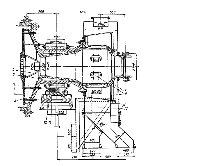
Both bearing sockets of the mill rest upon pivoted journal bearings to compensate for possible misalignment.
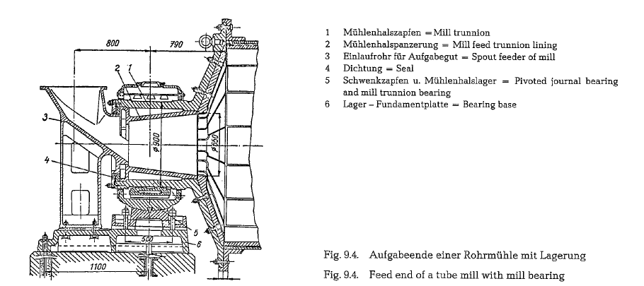
The two pictures Fig. 9.4. and Fig. 9.5, show cross-sections of the feed and of the discharge end of a tube mill, resceptively. The pivoted journal bearings supporting the main mill bearings are clearly visible. The pictures refer to a tube mill of the size 2.2 x 13 m, a product of the Soviet Machinery Works UZTM. Dimensions are in millimeter.
Continuous and close observation of the mill bearing temperature is very important. It must be understood that the temperature sensing device should be in direct contact with the bearing metal. Checking the temperature of the lubricating oil is unreliable and misleading; because of the low thermal conductivity of the oil, the bearing metal could become dangerously hot, before the oil temperature becomes indicative.
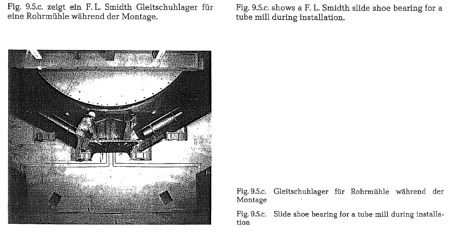
Mill slide shoe bearings
Slide shoe bearings are mostly hydrodynamic bearings. Bearings with slide shoes or riding rings are used for mills requiring a throughput of large volumes of hot gases thus avoiding a bottleneck for the gas flow.
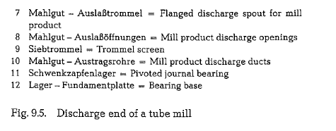
As shown in Fig. 9.5.a. (F. L. Smidth) a slide ring (1) rests in a slide shoe bearing consisting of two slide shoes with an incline of 30° placed on each side of a vertical line drawn through the center of the mill (see Fig. 9.5.b.).
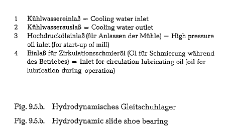
The two slide shoes, each consisting of a cast steel workpiece with white metal applied to the sliding path (2), are guided in axial direction by bronze rails(3) which fix the slide shoes in relation to the slide ring. The slide shoes rest on a ball segment (4) posi tioned in a ball socket (5). The ball socket is placed on a thrust block (6), which is placed upon two or more rollers (7), resting on a base plate (8).
The system of ball segment and ball socket with roll ers is able to absord any untruth of the slide ring. Further, the slide shoe bearing can move on the rollers when, during operation, the mill expands longitudinally.
Slide shoe bearings of the F. L. Smidth Co. are equipped with a high-pressure oil starting arrange ment. In order to ensure sufficient oil between slide ring and slide path before mill start-up, oil is pumped through a pipe inserted into the slide shoe in the cen ter line of the slide path. The oil injected under high pressure lifts the mill to reduce friction between the two metal surfaces. It is the same principle used for the start-up of tube mills with trunnions, which is described in section 9.4. (Mill bearings) of this book. During operation the slide shoe bearing is splash lubricated, i.e. the slide rings submerge into the oil bath at the bottom of the slide ring casing and pick up some oil, thus achieving hydrodynamic lubrication.
Advantages of mills with slide shoe bearings com pared to mills of conventional construction i.e. with mill heads and trunnions are according to mill manu facturers:
- Heavy mill heads can be discarded and replaced by covers of regular sheet metal, since they have nothing to Mill heads of large mills cause sometimes damage problems.
- By terminating the use of the mill trunnions, the mill becomes shorter by the same At drying-grinding mills the inlet and discharge openings can be kept large to prevent bottlenecks for the hot gases.
- Because of the shorter bearing distance also the mechanical stress of the mill cylinder is lower; therefore, the cylinder can be manufactured of thinner sheet metal
As predecessors of the slide shoe mill bearings, tube mills can be considered which were equipped with riding rings and rollers, exactly as it is the case at rotary kilns. In Europa such mills could be still found in operation in the 40s. Later, the F. L. Smidth Co. changed its Unidan mill, supplying one end of the mill with trunnion bearing, and placed close to the other end a slide ring with slide shoe bearing.
Bearing cooling of tube mills
The minimum amount of water required for cooling the bearings of raw mills (for dry grinding) as well as of finish mills is 20- 25 lit/min [97]. If the cooling water temperature is above 26 oc at the bearing inlet, more water will be required [98]. The average amount of bearing cooling water is assumed to be 50 lit/min per mill. Maximum allowable water pressure entering the bearing is 2 kg/cm2.
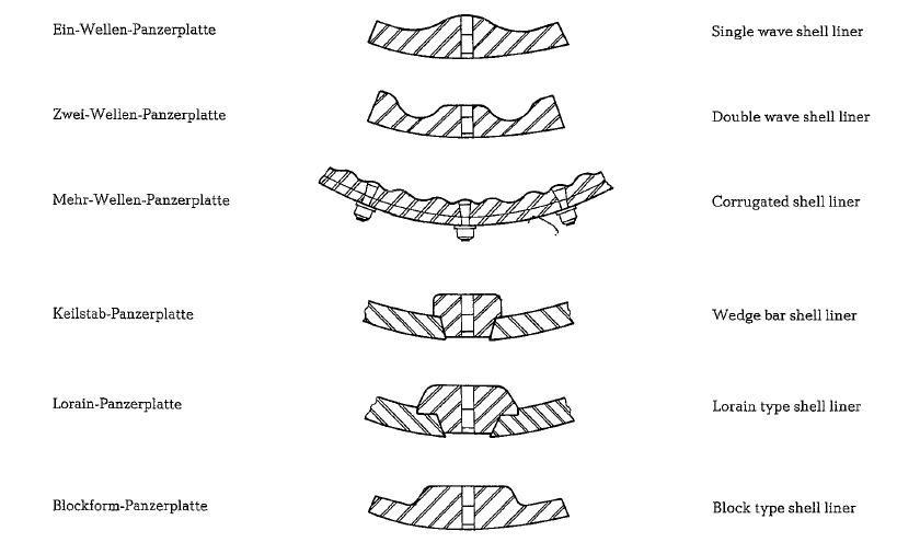
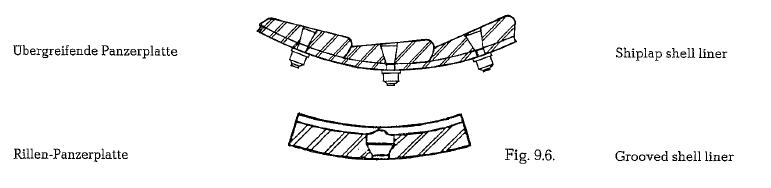
Surface shape of mill liners
The most frequent phenomenon of wear of mill liners is the formation of grooves. To counteract this circumstance, various surface shapes of mill liners have been developed to let the grinding media come down out of one of a variety of slideway arrangements.
speed, problems must be solved by properly shaping the mill liners, which is the only way to maintain cor rect motion and trajectories of grinding balls.
Fig. 9.6. shows various mill liners in current use.
The thickness of the mill liners depends upon the mill diameter as well as on the size of the grinding media and generally fluctuates within limits of 30- 63 mm. Shape of the mill liners is usually rectangular; dimensions are approximately 300-400 x 450- 650 mm. Corresponding weights are 50-125 kg.
Classifying mill linings
As early as in 1923, Mr. Carman, an American applied for a patent protecting classifying mill liners. How ever, this type of mill lining succeeded not earlier than in the past 5- 10 years.
The basic principle of the classifying lining is that the shape of the lining causes a classification of the grinding ball sizes, resulting in a decrease in size along the grinding path. This size adjustment of the grinding media to the increasing fineness of the prod uct, increases the grinding efficiency. This confirms the therory that the size of the grinding media should be adjusted to the fineness of the product, or in other words: the smaller the product, the smaller the grind ing media.
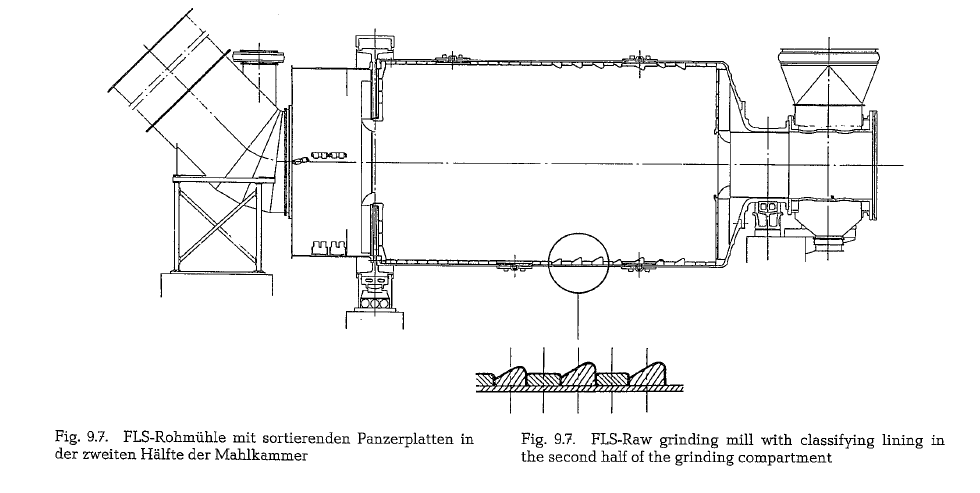
The following three illustrations show: a one-com partment raw grinding mill, a two-compartment finish grinding mill, and a two-compartment wet (slurry) grinding mill; all three mills are partially lined with classifying liners.
The raw grinding mill (Fig. 9.7.) consists of a drying compartment and of one grinding compartment. Only in its second half is the grinding compartment lined with classifying liners. This increases, according to the manufacturer (F. L. Smidth), the grinding capacity by 7- 8 %. The practical effect is nearly the same as in a mill with two grinding compartments, i.e. that all large grinding balls are concentrated in the first half of the grinding compartment. The picture shows fur ther that on its feed end, the mill rests on a slide shoe bearing, to provide a large inlet opening for the hot drying gases (FLS-Tirax-mill).
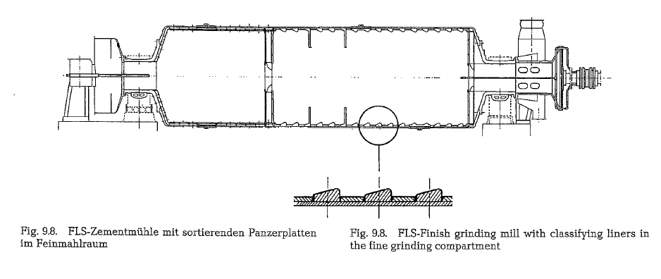
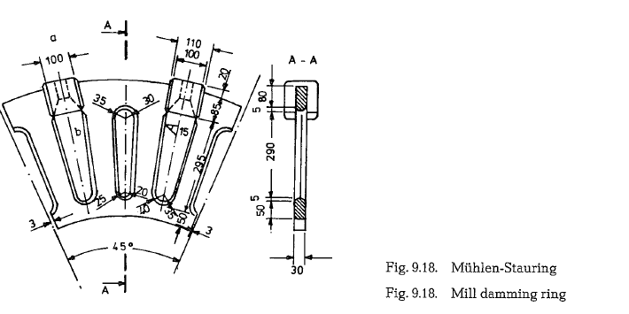
The finish grinding mill (Fig. 9.8.) is in its second grinding compartment supplied with classifying lin ing. To extend the residence time of the material inthe mill, this compartment is also provided with two damming rings (see chapter 9.10.). Practical experi ence proved that a two-compartment finish grinding mill with classifying liners, shows the same efficiency as a three-compartment mill. Coarse grinding com partments do not qualify for application of classifying liners.
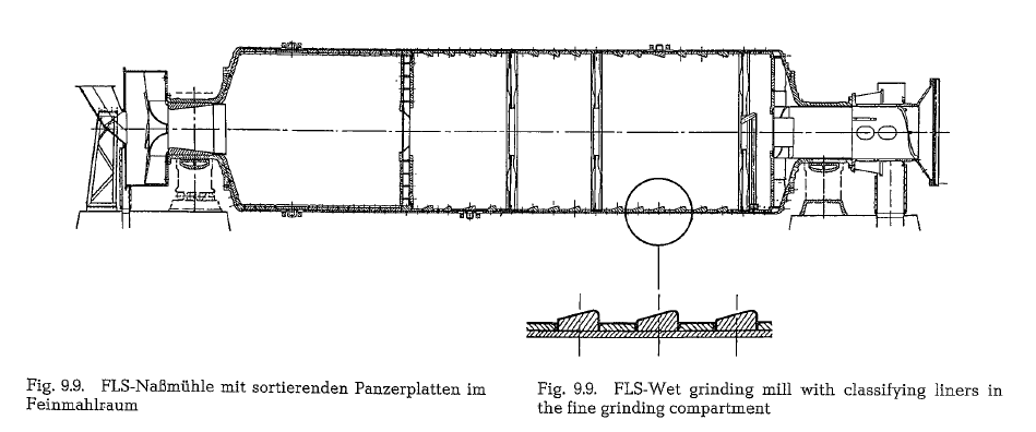
The fine grinding compartment of the wet grinding mill (slurry mill) shown in Fig. 9.9. is also lined with classifying liners. This compartment is further prov ided with three damming rings of which the last one is supplied with lifters, to return the grinding media. This ensures to keep the discharge grates free from small grinding media.
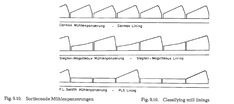
Fig. 9.10. shows three different design models of clas sifying mill liners.
Grooved shell linings
The slipping motion (friction) between the surfaces of the grinding media and the mill liners is greatly res ponsible for the wear which appears on the lining as washed-out grooves. Operators as well as suppliers of mill liners tried to overcome such wear which led to a multiplicity of surfaces and steel alloys.
T. Hukki of Finland [BOa, SOb] is of the opinion that the formation of such grooves is the result of some kind of mechanical self-help to improve size reduc tion, and that a mill will only then reach its full grind ing capability if and when the mechanism of slipping motion will be used to its full extent to grind the mill feed.
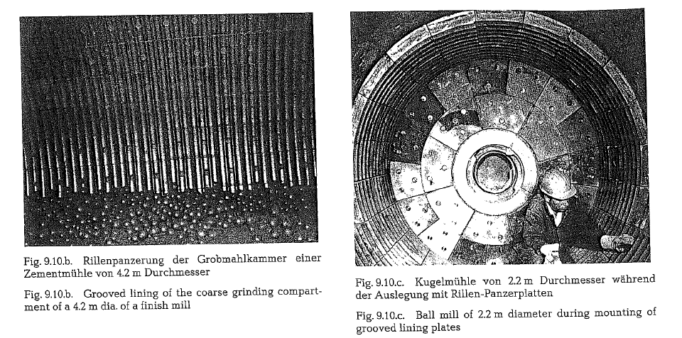
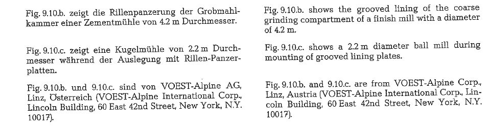
Systematic investigations of the phenomenon of for mation of grooves by F. J. Scheucher, Austria [SOc], led to the development of mill liner plates, having specific defined circumferential grooves instead of raised profiles. The expectations that such liners will improve the energy usage of the mill’s wall friction was confirmed, according to reports of the manufac turer of grooved mill liners, i.e. the VOEST-AlpineCorp., Linz, Austria. In all mill installations performed as yet with grooved liners in the coarse as well as in the fine grinding compartments, improvements were confirmed.
Not only reduction in wear but also a decrease in specific power consumption were noted. Grooved liners can also be manufactured as classifying liners. According to the manufacturer, the VOEST-Alpine Corp. the expedient method of grinding motion along grooved liners improves the economics of the mills by reducing the power requirements by about 20 %, and improving the production rate by about 10 %.
The specific motion of the grinding media on grooved liner plates allows the implementation of chromium alloys having the highest wear resistance. In addition, such alloys are further surface hardened by the peen ing effect during the grinding process.
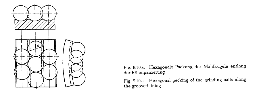
The grooved profile supports the normal behavior of the grinding media to form the tightest packing possi ble. Inspite of the unavoidable wear in any grinding process, the liners retain the grooved profile over their total life-span.
The lower liner weight has the advantage of easier handling during their installation inside the mill, compared to normal liners with a raised profile. Grooved liners for the coarse grinding compartment weigh approx. 15 % less, and for the fine grinding compartment, designed as classifying liners, the weight of the plates is even 30 % less. Breakage of liners or bolts will not occur, due to the specific motion of the grinding media which is characteristic for grooved mill liners. Unproductive hammering of the media on bare liners is almost totally avoided.
According to the manufacturer, the consumption of grinding media is reduced by about 40 %, due to the hexagonal packing of the grinding balls (see Fig. 9.10.a.). This tight packing, supported by the grooved liners, gives the mill feed less possibilities to move out from the mass of the grinding media, which in turn avoids direct contact of the grinding balls with the mill liners.
Fastening of mill liners
Generally tube mills are supplied with bolted liners,i.e. each liner plate is fastened to the mill shell with one or two bolts and sometimes as many as four. To increase the strength of the mill shell and simulta neously lower the maintenance costs of the bolted joints, two forms of lining construction have been developed: the lining using only a few bolts, and more recently, the boltless lining.
Fig. 9.11. shows a new mill liner design where only every other liner is bolted on and the intermediate liner is locked in by neighboring liners, reducing the number of bolts by half.
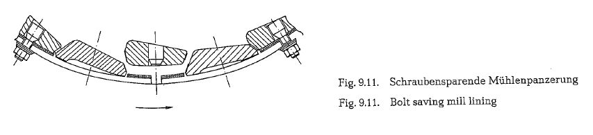
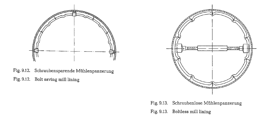
Fig. 9.12. shows a possibility of additional saving. According to this, only four liners are bolted to the mill shell and a larger number of liners are locked in by the bolted liners. At the steady increase of mill diameters however, security reasons require that boltless linings be supplied with two to four axially bolted plate rows.
Fig. 9.13. shows a mill shell with boltless lining. For this design the liner ring inside the mill must be self supporting. The liners must be thick enough to provide for wedge shaping.
First the lower half of the mill tube is lined and the endliners braced with jacks; the mill is then rotated to facilitate lining of the other half of the mill.
Mill partitions
Special partitions divide the cylinders of compound mills into several compartments; during grinding each compartment has to accomplish a specific func tion.
The partitions or diaphragms are designed to prevent passing of oversize particles to the next mill compart ment. The slots in the partitions allow only preground material of a certain particle size to pass. The design and dimensions of the partitions influence the fine ness of the ground material as well as the mill per formance.
Mill partitions are designed as single or double wall partitions.
Single wall partitions allow preground material to pass without special classification. The material being ground is pushed towards the partition by new feedentering the mill; after passing through the slots, the material enters the next mill compartment. The open ings in the center of the partitions are for mill venti lation (see Fig. 9.14.).
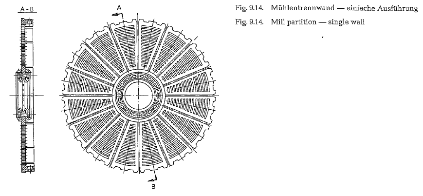
Fig. 9.14 shows a single wall partition consisting of 16 sectors of a mill 2.2 m dia x 13m long (USSR-UZTM mill).
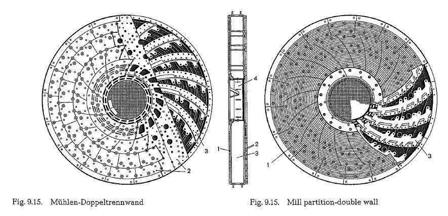
Double wall partitions are usually installed between the first and the second mill compartments. Fig. 9.15. shows a double wall partition (Christian Pfeiffer Co., Beckum, W. Germany). The partition consists of two front walls 1 and 2, which are fastened independently of each other by multisectional platings, thus taking into consideration and protecting special wear zones. Also when changing the plates, it is not necessary to remove the liner plates from the mill cylinder. The material comminuted in the first compartment comes through the slots of the entrance plates 1 into the curved cascader 3. There, the ground material is lifted and led against an axially adjustable pipe 4. Accord ing to the position of this central pipe, the transporta tion of the ground material from the cascader is throt tled in such a way that the entrance of the ground material into the partition wall is controllably delayed. In this way the level of the ground material dams up within the level of the grinding media in front of the partition wall and undergoes in this way an intensive size reduction. The easy access to and fast adjustment of the pipe follows the detection of the optimum operational requirements and is, as a rule, retained for a longer period of time.
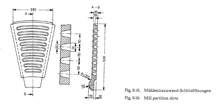
The mill partitions are sectioned so they can can pass through the manholes of the mill. The slots of the par titions are either radial or circular. On the exit side of the wall the slots are 1.5 to 2 times wider than on the material entrance side. Such shaping prevents a pos sible blocking of the slots with mill feed (see Fig. 9.16.).
Active surfaces of mill diaphragms
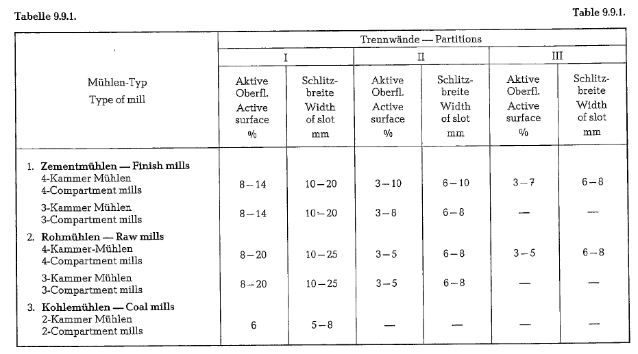
The ratio of the total slot surface to the total surface of the partition has a significant influence on the per formance of the mill. The width of the slots depends on the length of the particular mill compartments, on the quality of the mill feed and upon the size of the grinding media. The total slots opening is the so-called active surface of the mill partition and is expressed in percent. The magnitude of the active surface and the width of the slots varies within the limits shown in table 9.9.1.
The active surface of the partitions increases with time; abrasion causes widening of the entrance open ing of the slots.
In the Soviet Union mill partitions and mill liners are made of cast steel (brand 70 Chl), having the following chemical composition:
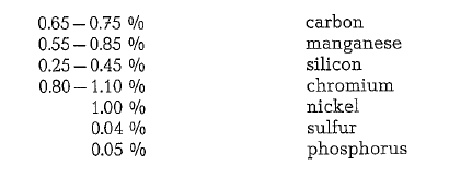
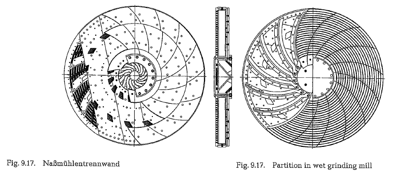
In addition to the above described double wall parti tions with a central throttling arrangement for the ground material, also double wall partitions are in use with a central discharge arrangement, either as an open truncated cone shell or with angled sheet steel mounted on the scoops. At wet grinding mills a closed, centrally located deflection cone is used (see Fig. 9. 17., Christian Pfeiffer Co., Beckum, W. Ger many). Besides, there are double partition walls with double sided slot plates for a peripheral discharge of the ground material through discharge openings located in the mill shell. Finally, there are mill parti tion walls which divide the drying compartment equipped with sectional lifters from the grinding compartment filled with grinding media.
Active surfaces and slot widths of mill diaphragms
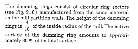
Damming rings
Where necessary, grinding compartments of multi compartment mills are also equipped with one or two additional partitions, called dams or damming rings. The function of the dams is to impede the material flow in the mill. This prolongs the residence time of the material in the mill and results in better fine grinding.
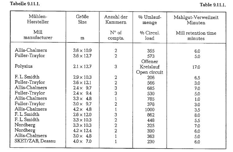
Retention time in tube mills
Table 9.11.1. contains retention times of mill feed in tube mills of different sizes, compartments, and circu lating loads. The retention times represent results of tests performed with fluorescein to trace the material through the mill
Starting of new installed tube mills
Manufacturers recommend operating a tube mill without load of grinding media for a 48 hour period to make sure the trunnion bearings are operating satis factorily and capable of taking a heavier load. The mill is then run 150 hours with 50 % ball charge and another 150 hours with 80% grinding ball charge before being run at full load.
A ball mill should not be operated without feed for any length of time as this causes unnecessary wear of the grinding media and liner.
For successfull operation of a mill, it is necessary that the feed be properly regulated. This can be easily judged by the quality of the finished material and by the sound of the mill. A mill running empty has a decidedly metallic ring, indicating that grinding media are falling on the clean metallic surface of the liners. If the mill is overfed, there is a partial or entire absence of metallic ring, depending on the amount of feeding. With proper feed rate, a sound between these two extremes is obtained.