Contents
CLICK HERE TO DOWNLOAD EXCEL SHEETS , BOOKS , MANUALS , OPERATION MANUALS , REFERENCE BOOKS , PROCESS BOOKS
Finish grinding
The finish grinding process is one of the basic tech nical operations of cement production as well as the concluding process. The manner in which this opera tion is conducted, determines the quality of the cement.
It is useless to grind cement to a large specific sur face, but the ground product must obey certain laws relative to particle size distribution in order to favor the ensuing hardening process.
The technology of finish grinding is based on the fol lowing observations:
The particle size fraction from 3 to 30 microns is con ducive to the strength development of the cement. The particle size fraction below 3 microns contributes to the initial strength only. This particle fraction hydrates fast and after one day results in the highest compressive und flexural strengths. The fraction above 60 microns hydrates slowly and contribute lit tle to the strength of the cement.
The particle fraction from 3 to 30 microns should be represented as follows:
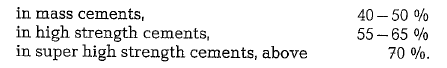
The values shown above are only orientation figures; the development of strength is dependent upon the particle structure as well as the mineral composition of the cement.
Higher particle fineness (approximately 5000 cm2/g Blaine) has no influence upon the development of strength. On the contrary, it lowers the strength.
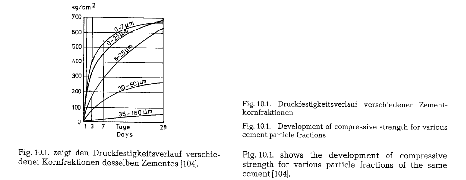
The curves shown above (Fig. 10.2.) [105] make it pos sible to read the specific Blaine surface (cm2/g) for particle sizes from 0- 100 microns; this is for a cement with a specific gravity of 3.1 grams/cm 3. These curves are an aid in determining the approxi mate specific surface of known particle sizes or vice versa.
Fig. 10.3. shows the correlation between sieve residue (sieve 0.09 of German Standards DIN 4188, equal approx. to ASTM sieve No 170), and specific surface (cm2/g) of Portland cement. This is useful in determin ing the approximate specific surface of a known sieve residue. However, this curve is for orientation pur poses only, since sieve residue and specific surface are different, depending on the material and grinding system.
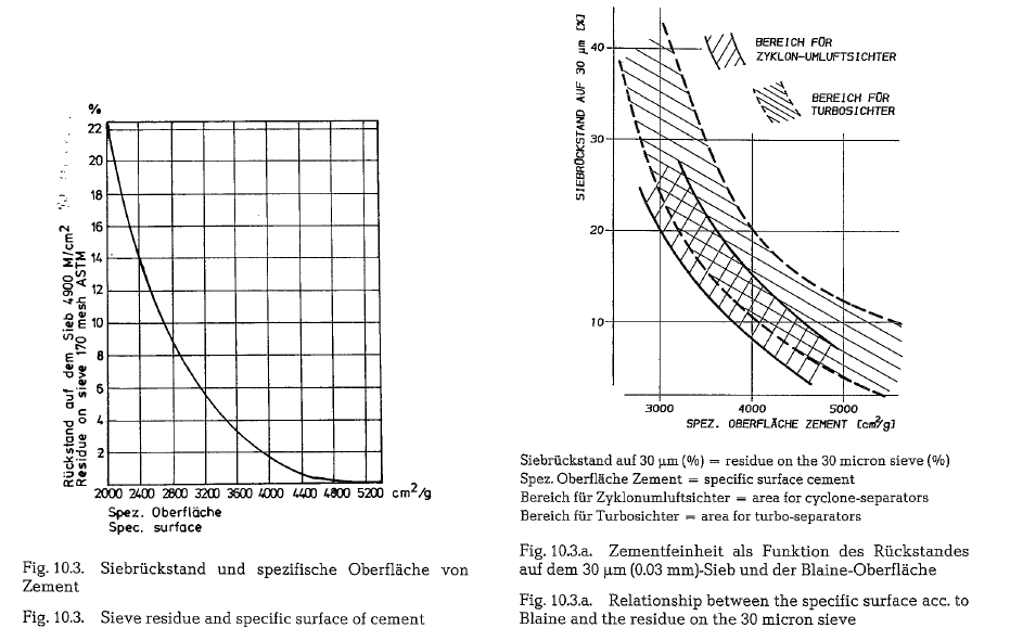
Fig. 10.3.a. shows the relationship between the spe cific surface ace. to Blaine and the residue on the 30 Micron sieve of various types of separators. The area between the dotted curves shows the relationship in the case of various types of turbo separators, while the area between the solid lines shows the situation in the case of plants equipped with cyclone separa tors
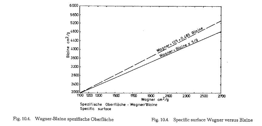
Wagner and Blaine specific surface
In connection with Bond’s formula, the ratio of the Wagner-surface to the Blaine-surface was given on table 6.4.1. In order to check the conversion factor, a number of Blaine and Wagner laboratory results were plotted on Fig. 10.4.
Two conversion factors are in use: the 5/g-factor and the 125+ 0.485 Blaine factor. Either conversion method is merely a practical way of obtaining the surface value; the ratio will vary somewhat for different materials.
Remark to ‘Specific Surface
Fineness requirements for Portland cement are stated in terms of specific surface in square centimeter per gram and measured by two alternate methods: air· permeability and turbidity.
The Blaine air permeability test utilizes the D”Arcy Kozeny relationship which states that the flow of a fluid through a packed bed of granular particles is related to the surface area of the particles in the bed.
The Wagner turbidimeter is based on Stokes law for particles settling in a fluid. The concentration of par ticles indicating the specific surface is measured by the intensity of a light beam passing through a sus pension of the material.
While both Blaine and Wagner fineness values are expressed as specific surface in square centimeters per gram, the values are obtained from entirely differ ent relationships and are not comparable. Both sur faces are not identical with the true specific surface of the test substance, but each gives a usable relative value in the practically important range of cement fineness
Grinding aids
Grinding aids are materials which facilitate grinding in ball or tube mills, by eliminating ball coating or by dispersing the ground material. When grinding cement, the additive must also have been shown not to be harmful to the finished cement.
Grinding aids may be added in solution, as solids to the mill feed or directly to the mill itself.
The addition of a fluid may be more readily con trolled than the addition of a small amount of granu lar material. Grinding aids are metered in quantities from 0.006 to 0.08 % of the clinker weight.
The majority of grinding aids are substances which become strongly adsorbed by the ground particles, so that surface energy requirements are satisfied and no bonds remain to attract other particles and cause agglomeration.
Grinding aids prevent ball coating and consequently mill efficiency is increased. Grinding aids reduce power costs thus paying their way. Savings of 2.5 US cents per ton of cement, depending upon the specific surface, are reported.
Grinding aids also increase the efficiency of air sepa rators by dispersing the particles so that the smaller ones are not carried along by the larger. There is a decrease in volume of the circulating load as a result of more fines being released as finished product.
Grinding aids in themselves, do not have a major effect on strength.
Although they may reduce early strengths, 28-days strengths are about normal.
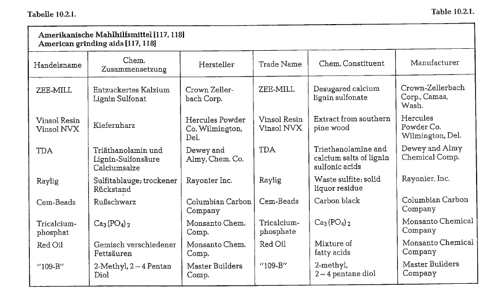
By elimination of the surface energy forces which normally cause interparticle attraction, grinding aids improve cement flowability after grinding. ASTM Standard Specifications for Portland Cement permit the use of two commercial grinding aids “TDA” and “109 B” (see table 10.2.1.).For raw materials a wide variety of additives includ ing coal, graphite, colloidal carbon, coke [80], colo phonium, fish oil stearate, etc. may be used as grind ing aids.
Slurry thinners have a beneficial effect on grinding in wet process raw mills; they have a deflocculating effect and are surface active
In Germany, the following grinding aids are employed in the grinding of finished cements:
Amine acetate
Ethylene glycol
Propylene glycol.
Grinding with propylene glycol generates approxi mately 800 cm2/gram cement more surface than grinding without an aid, given the same energy con sumption.
The cost of these grinding aids is about 0.25- 0.40 U.S. Dollars/kg. The grinding aid is added to the cement in an amount of approximately 1 kg/t.
The following increase in mill throughput was reported: 10-30 % when grinding Portland cement N° 375 (equal to compressive strength of 5321 psi after 28 days), and 25- 50 Ofo when grinding Portland cement No 475 (equal to 6740 psi).
Coating of grinding media
Grinding ball coating which impairs further commi nution is the accumulation of finely ground material on the surface of the grinding media.
Causes of ball coating are:
- Static electricity – Very fine particles in a mill become charged, and, if different materials are being ground, one part becomes positively charged and the other negatively. These opposite charges attract each other and the particles agglomerate
- Surface energy forces – Atoms or groups of atoms on the surface of a solid may not be com pletely saturated as to their valencies and form non-homogeneous fields on their surface
- Adsorption – Individual particles adsorb a sur face film of air. Presumably this film tends to pre vent the particles form combining. However, if this film is removed in some way, the particles may then be free to combine more readily.
- Mechanical impact -This theory states that the grinding balls strike each other with such impact that the particles of material are rammed together and tamped upon the uneven ball surface.
Generally, ball coating cannot be explained by a single theory.
Factors contributing to ball coating:
- Ball coating increases with elevated temperatures
- When ground with clinker, gypsum has a ten dency to prevent ball coating; however, dehy drated gypsum causes ball coating.
- Aged clinker has a higher tendency to cause ball coating than freshly burned clinker. But generally, aged clinker grinds more easily than freshly burned clinker because of the slaking of free lime. The slaking action tends to weaken or break down the structure of the clinker, apparently because of expansion of the lime as it hydrates during aging. Blaine readings on fresh and aged clinker showed that when ground for the same number of revolu tions under the same conditions, aged clinker gave higher surface areas. The aged clinker had 4405 cm2/g, whereas the fresh clinker had 3340 cm2/g
- Rough surface balls accumulate coating while smooth surface balls do not.
Effects of chemical and potential compounds on grindability
Portland cement is a conglomerate of minerals gener ated during the burning process and solidified by the liquid phase (see chapter 1.4., Components of Portland cement). Chemical composition and calculated poten tial compounds have been plotted against grindability in a grindability test mill. The grindability is expressed in grams per mill revolution of the ground material, passing the 200 mesh sieve (ASTM).
The following grindabilities (Fig. 10.10., 10.11., 10.12.) are based on a definition which states that grindabil ity is a coefficient indicating how many times faster the tested material is ground in comparison with a standard sample; grinding is performed up to 10% residue on the 170 ASTM-sieve.
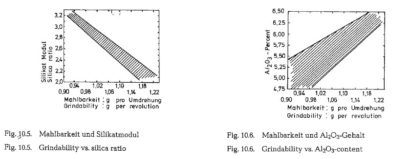
Fig. 10.10. shows the correlation between the grinda bility coefficient and the C3S-content. According to the diagram the grindability increases linearly with increase of the C3S-content of the clinker. The same applies to the lime saturation ratio (LSR), and clinker grindability shown in the diagram.
The lime saturation factor is expressed as the Kind Modulus (KM)
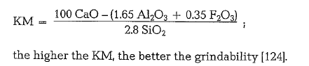
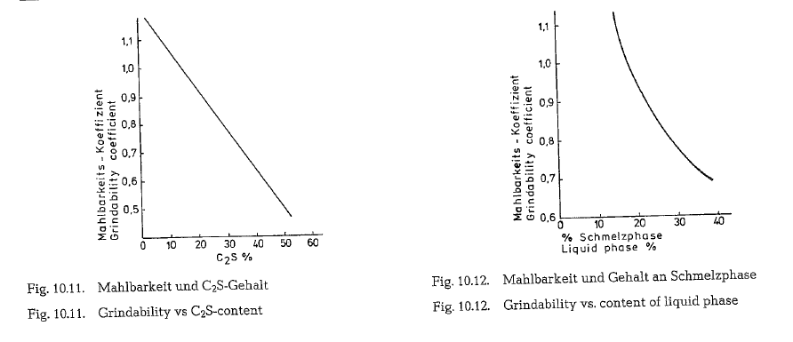
Fig. 10.11. shows the grindability versus the C2S-con tent of the clinker; a high C2S-content results in a lower grindability due mainly to coating of grinding media and adsorption.
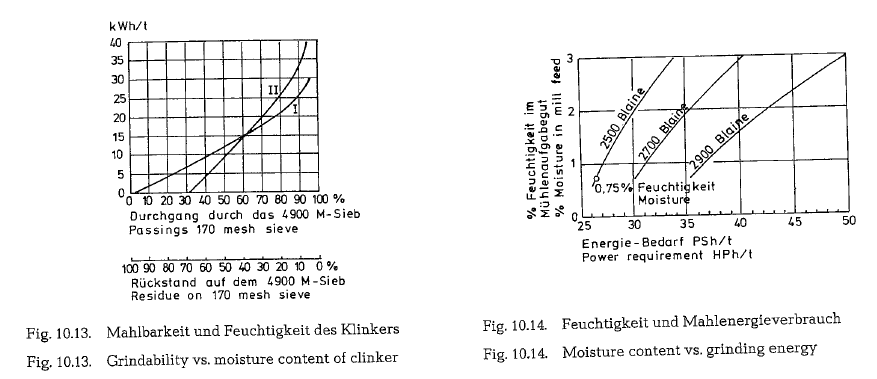
Fig. 10.12. shows the grindability of clinker versus the amount of liquid phase in the clinker. Generation of clinker minerals occurs partially in the liquid phase. The amount of liquid phase influences the compact ness of the clinker and thus its grindability. The more liquid phase, the lower the grindability of clinker.
Effect of moisture on the grinding process
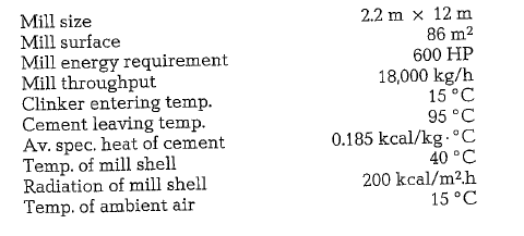
Fig. 10.13. shows how the moisture content of clinker influences grinding efficiency. To demonstrate this, the same clinker with different moisture contents was ground in the same mill.
Diagram I: clinker containing 0.4 % moisture
Diagram II: clinker containing 2.4 0/o moisture.
One can see that at 90 0/o passing through the 170 sieve the clinker with 2.4 0/o moisture consumed 8 kWh (10.7 HPh) more energy per metric ton than clinker with 0.4 0/o moisture. It is noteworthy that a higher moisture content of mill feed has a detrimen tal effect on the grinding process for the entire dura tion of grinding
This higher spec. energy consumption can be avoided by passing hot gases through the mill (combined grinding/ drying) or by pre-drying the moist material in integrated driers (flash driers)
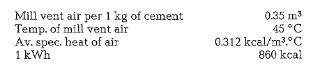
Further examination shows the influence of the mill feed’s moisture on the required grinding energy when grinding to different Blaine numbers. The results of the experiments are pictured by the graphs given in Fig. 10.14.
Indeed, the given curves do not relate to cement or cement raw mix, but represent results of practical grinding of iron ore with different mosture contents in a one-compartment tube mill (size 4.25 x 11.7 m, open circuit, 4400 HP drive). Bond’s work index for grinding of this ore was determined to 12.7 kWh/ton. According to this, an increase in moisture of the mill feed e. g. from 1 to 2 % when grinding to 2500 Blaine requires an additional grinding energy of 10 % or 3 HPh/t. When grinding to 2900 Blaine the additional energy consumption is already up to 15% or 6 HPh/t. Going on with the same Blaine number and increas ing the moisture from 1 to 3 %, the requirement for additional grinding energy becomes 26 % or 13 HPh/t.
Grinding and generation of heat
All size reduction machines, especially ball mills, con vert the majority of energy input into heat. The heat ing is such that the temperature of the mill feed increases to more than 100 a c. The heating of the mill feed during dry grinding of cement raw mix has no detrimental effects. Also at these temperatures the chemical properties of the clinker remain unchanged. However, admixtures such as raw gypsum added to the clinker during grinding, are sensitive to these temperatures. The dehydration of raw gypsum starts at a temperature of 105 oc. At high grinding temperatures a partial separation of the gypsum’s water of crystallization occurs and the gypsum loses its pro perty as a cement setting retarder; such a cement becomes a so-called false set cement, which, when mixed with water sets to a hardened mass immedia tely or within a few minutes.
Heat generation in tube mills
In the following practical example, heat generation in tube mills and the resulting losses of efficiency are given. The figures used are average values which resulted from practical mill operations
Based on the figures given above the reduction work loss and heat generation is calculated as follows:
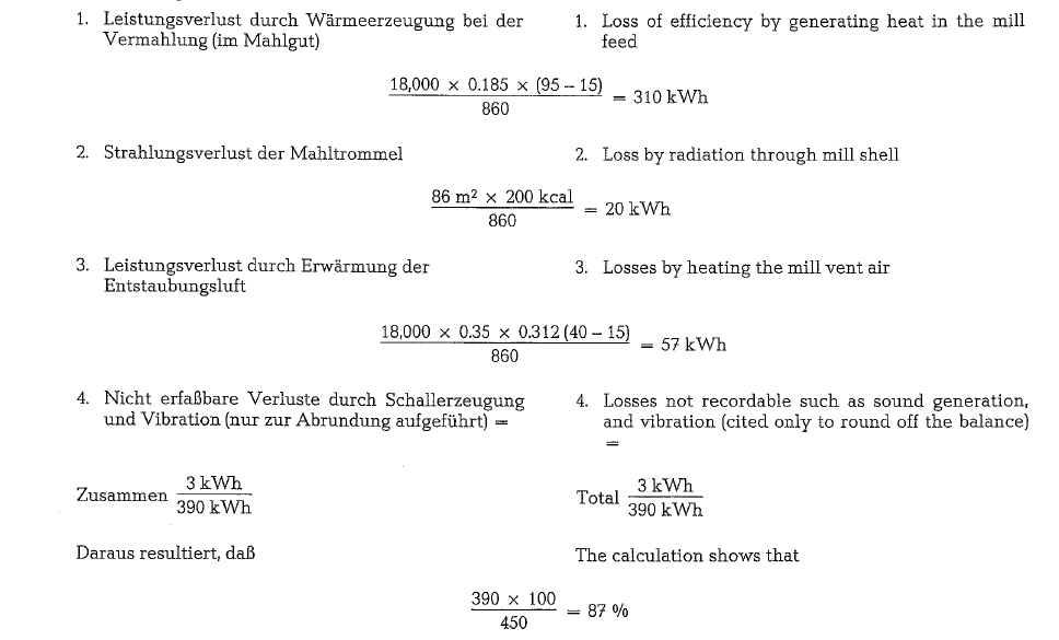
of the power input was converted into heat.
Cooling procedures during finish grinding
With present day grinding temperatures and product specifications, open circuit grinding is not completely feasible. For best results, cooling must be done in the grinding mill circuit, often in the air separator. Cool ing is effective only so long as temperatures do not reach the dehydration point of the gypsum. This criti cal temperature is very often attained in open circuit grinding. Closed circuit grinding provides better tem perature control over the complete grinding circuit.
Several cooling concepts have been introduced:
Mill ventilation
Normally about 0.2 m3(min of air per mill kW is drawn through a single compartment mill, compared to 0.12-0.4 m3/min per mill kW in a multicompart ment mill
For effective cooling Lurje [129] recommends for mul ticompartment mills an air exchange rate of 300 m3 per ton of cement per hour. Other recommendations for intensive mill ventilation quote figures for vent air from 400 to 1200 m3 per ton cement.
Arithmetically mill ventilation can also be expressed in mill volume; this figure amounts from 3 to 4 times mill volume air exchange per minute. Under usual conditions for mill ventilation, normal dust concen trations can vary from 400 to 800 g/m3
For mills working in open-circuit systems the air vol ume is determined by the air velocity in the free cross section of the mill. The air velocity should not exceed approx. 1.0 m/s.
Water-cooling of the mill shell
If the mill ventilation is not sufficient to lower the grinding temperature, cooling of the mill shell can be of help. A water sprinkler system installed along the longitudinal mill axes, sprays water on the mill shell. This kind of mill cooling lowers the temperature of the mill discharge by 30 to 40 o C.
Water injection into the mill
This cooling system is based on injection of a con trolled amount of water into the hottest part of the finish mill where it is evaporated instantaneously. Water is carried into the mill by compressed air through a simple nozzle which breaks up the water into very small droplets. In two-compartment mills the atomizing nozzle usually extends into the second grinding compartment. The resulting mixture of air and water vapor is swept out of the mill, passed through a dust collector and discharged to the atmos phere. Ducts and dust collector are insulated to avoid condensation of water vapor.
Owing to the low mill ventilation rate mentioned in point 10.7.1. for mills working in open circuit (Vmax. = approx. 1.0 m/s), it is necessary for cooling water to be injected into the 2nd grinding compartment, if the mill is to function under optimum conditions.
In the case of high clinker temperatures, water can be injected into both compartments (of 2-compartment mills).
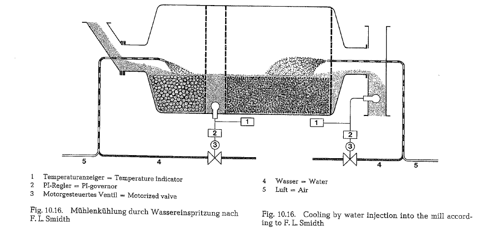
Fig. 10.15. shows a schematic presentation of injection of cooling water into a finish mill (Fuller Co., Bulletin WS-lA).
The .following illustrative examples show the effectiveness of spray water cooling in finish mills.
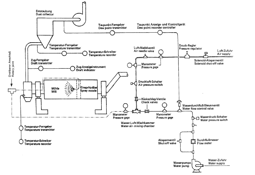
Fig. 10.15. Cooling by water-injection into the mill
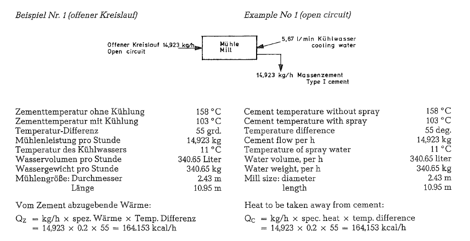
The heat absorbed by the water in this case is greater than the heat given up by the cement; inaccuracies in the measurement of water and temperatures could account for this condition.
Since more heat is given up by the cement than is absorbed by the water, air circulation through the mill must have helped cool the cement down to dis charge temperature
The F. L. Smidth Co. applies a finish grinding mill cooling system in which the water injection into the first grinding compartment is controlled by the tem perature of the material in the first diaphragm, while the water injection into the second compartment is controlled by the temperature of the ground material at the mill outlet; see control-scheme Fig. 10.16.
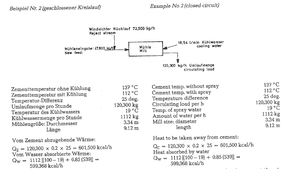
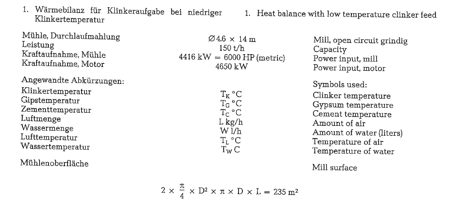
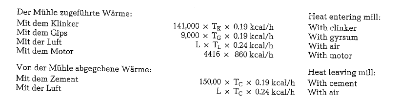
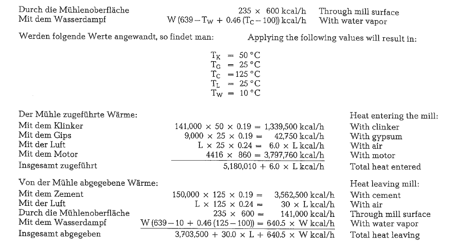
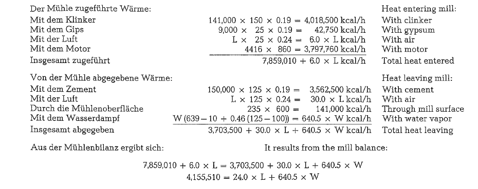
In the following, two heat balances for mill cooling according to the F. L. Smidth-system are calculated [87c]; the first heat balance refers to a mill feed with a low clinker temperature (50 °C), whereas the second is calculated on the base of a mill feed with a high clinker temperature {150 oc).
Aftercooling of cement
The above calculations show that despite water cool ing in the mill, the cement exit temperature is over 100 o C. As is known from experience, storage of cement and packing into paper valve bags, require a reduction of the cement temperature down to about 65 oc.
Due to its high specific heat, a signifant drop in tem perature can be achieved only by the application of on appropriate cooling method. During conveying from the mill to the storage silo, the cement tempera ture is lowered only by about 5- 10 deg. C; the cool ing process in storage silos lasts several weeks.
When packing hot cement (about 80- 100 oq into paper bags, the paper fiber deteriorates, and the bags often tear apart. When storing hot cement in silos, lumps are often formed as a result from a reaction between the clinker minerals and the water of hydra tion of the gypsum (formation of syngenite).
The F. L. Smidth cement cooler reduces the cement temperature from 110 o to 65 o, when applying cooling water of 15 oc (see Fig. 10.17.).
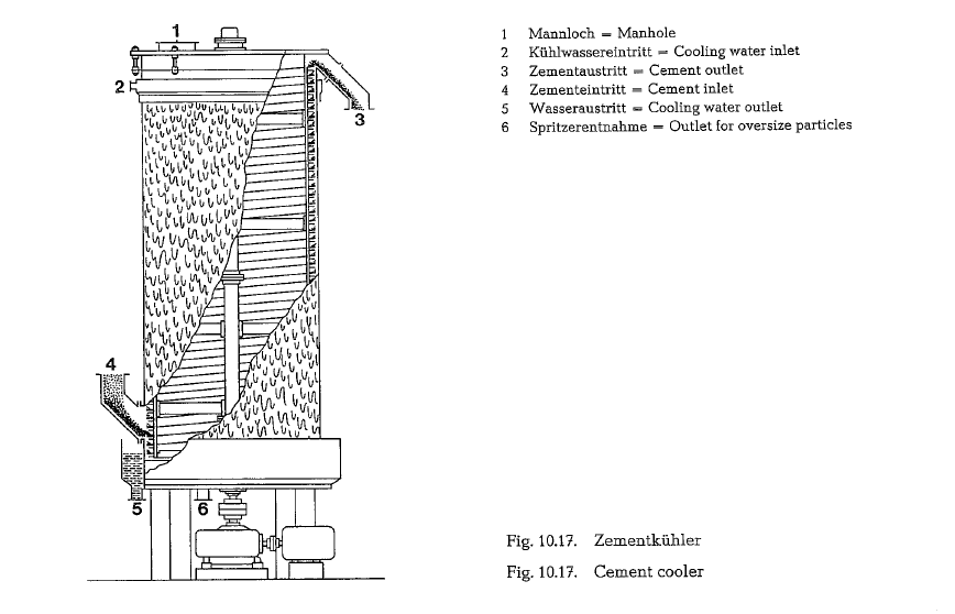
The hot material is fed to the bottom of the cooling tank, and picked up by internal rotating spiral flights.
By the combination of the vertical movement with the centrifugal force acting upon the material, the cement forms a thin, upward moving layer, pressed against the inside of the tank shell. This results in a high rate heat transfer from the hot material to the cold tank shell.
The heat is transferred through the tank shell and carried off by the cooling water, distributed evenly over the circumference of the shell, and cascading continuously as a thin film downwards, to be col lected in a trough below the tank, and discharged.
For discharging of foreign matter accumulating in the tank, the cooler’s bottom is provided with a special outlet.
This cooler can also be inserted into existing installations.
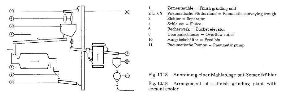
Fig. 10.18. shows a flow diagram of a grinding plant with an F. L. Smidth cement cooler.
The F. L. Smidth cement cooler is manufactured for capacities up to 100 t/h; for this cooler size the con sumption of the cooling water is 65 m3/h, and the power input is 90 kW.
After expiration of the patent rights the described cement cooler is being built by many cement machi nery manufacturers. So e. g. the Krupp Polysius Co. manufactures this cement cooler in various sizes up to a maximum throughput of 160 mt/h
Cement cooling in mechanical air
Here cement cooling is attainable at low power con sumption. For this kind of cooling the end product and circulating load are cooled simultaneously, thus avoiding heating to the dehydration temperature of gypsum. The cooling air amounts from 0.20 to 0.30 kg/kg of cement (circulating load + finished product), depending upon the temperature of the cooling air and the circulating load. The thermodynamic conditions and the amount of cooling air must be deter mined by a separate heat balance for each grinding mill.
Fig. 10.19. shows a flow chart of a finish mill working in closed circuit with an air cooled mechanical air separator. The circulating load amounts to approxi mately 290 % of the new feed. All product quantities and temperatures are shown in the flow chart. The quantity of cooling air is 0.28 kg/kg of cement (circulating load + finished product). The particular temperatures are: finished product 81 oc. separator coarses 85 oe, and dust precipitator product 74 oc.
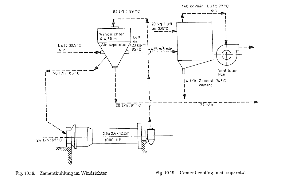
The accuracy of the particular figures can be checked by the following calculation based on the assumption that the heat lost by the cooled cement equals the heat gained by the heated air. The amount of heat in each case is obtained by multiplying the mass (M) of each component by its specific heat (S) and by the change in temperature. The resulting final tempera ture is marked as t1. The product quantities are expressed as kg/min. The heat lost by the cement as it cools in the separator to the final temperature t1 is:
Mean temperature of the three components is 84 °C; the difference between the calculated and the given temperatures is only 3 deg. or roughly 3 %, which is negligible for these conditions. The calculation illus trates the degree of accuracy of the figures given in the flow chart of the grinding circuit.
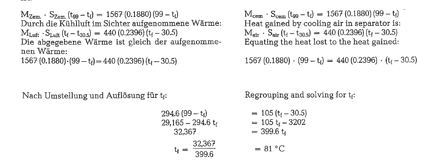
Cement cooling in Heyd-air separator
Heyd [132] quotes the following figures for cement cooling with air in the mechanical air separator of his design:
Cooling in Fuller’s cement cooler
Fig. 10.20. shows a cement grinding circuit where cooling of the circulating load is performed in a special cement cooler which the manufacturer calls Fluidized Material Cooler [133]. This cement cooler is basically a circular tank containing cooling tubes. The tubes are connected to form circuits. The number of tubes and circuits vary with the diameter of the cooler. Water enters each circuit from a supply header and exits to a discharge header that may either be connected to a sewer or recycled through a cooling tower. At the bottom of the tank below the tubes is a sloping bottom equipped with a porous medium. The porous medium is compartmented with an air supply to each compartment. That may be var ied by means of butterfly valves, to control fluidiza tion in the cooler. The fluidized material cooler reduces the temperature of the material throughout the grinding circuit to approximately 80 ac and thus minimizes the possibility of gypsum dehydration. At the same time the finished cement temperature is between 50 o C and 65 o C, depending on cooler size, temperature of cooling water and capacity. No cool ing in the air separator is necessary.
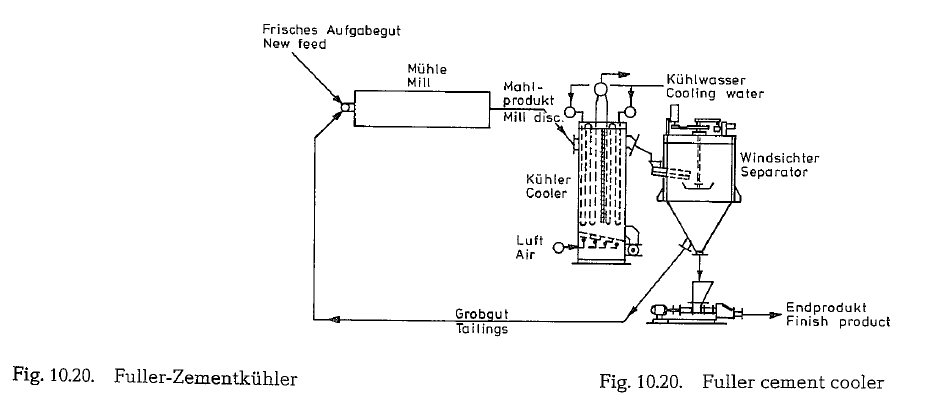
If the mill product is cooled adequately (to prevent gypsum dehydration) by mill water spray or in a separator, a fluidized material cooler may be utilized to cool just finished cement.