Contents
Harvesting Waste Heat from Cement Kiln Shell by Thermoelectric System

Mojtaba Mirhosseini, Alireza Rezania*, Lasse Rosendahl Department of Energy Technology, Aalborg University, Pontoppidanstraede 111, 9220 Aalborg East, Denmark
Attention!! to Download Most Important Books in Cement industry reviewed from more than two thousands people + Manuals and noted from big Cement Companies like F L S , Holcim Lafarge , Cemex , + Excel sheets for calculations process Click here Now
Abstract
Waste heat recovery in high temperature industries such as cement factory has undeniable benefits. In this study, an annular panel is considered as the thermal absorber around the external surface of the kiln at the location with highest surface temperature along kiln. By using a comprehensive numerical simulation, the temperature on the absorber is obtained and utilized as the hot side boundary condition of thermoelectric generator (TEG) system. For efficient design of the thermoelectric unit on outer surface of the absorber, effect of critical parameters such as thermoelectric leg length and fill factor are studied. Two different thermoelectric materials, bismuth telluride (Bi2Te3) and β- phase zinc antimonide (Zn4Sb3), efficient over different ranges of temperature are considered in order to evaluate electrical power output and performance of the system. Matched power output and conversion efficiency of the system are investigated. A double- objective optimization is carried out to minimize cost per power. The results show, the optimum leg length obtained by analysing cost per power ratio is shorter than the leg length corresponding to the maximum peak power output at a fixed fill factor. Zn4Sb3 shows higher conversion efficiency at maximum peak power output than Bi2Te3, except for fill factor of 0.01.
Keywords: Cement Rotary Kiln; Waste Heat Recovery; Computational Fluid Dynamics (CFD); Thermoelectric Modelling; Design Optimization; Economic Evaluation.
Introduction
Cement rotary kiln is the main device implemented for industrial cement production in large scale. In this type of rotary kilns, basic raw materials are continuously heated through the kiln length; therefore, the materials are dehydrated, preheated, calcified, and combined into the cement clinker. Significant amount of the heat produced in the rotary kiln is lost from the kiln shell [1]. Different methods for waste heat recovery from the external surface of the cement kilns has been proposed in the past, but these approaches can only be used for heating fluids in heat exchangers for indirect energy harnessing [1-12].
Thermoelectric generators (TEGs) can be utilized in practice for waste heat recovery and convert the heat directly into electrical energy. Distance of the TEG system to the rotary kiln should be as small as possible
for high density power generation. On the other hand, the thermoelectric modules should not be installed directly on the kiln surface, because of increment in the kiln’s weight, which would require more energy for rotating. A more robust structure is also needed to counteract the weight and, therefore, the equipment costs increase. On the other hand, the cement kiln constantly rotates during operation and, therefore, for installation of the recovery system directly onto its surface the system has to shut down. Furthermore, a direct contact increases temperature on the kiln surface that can cause cracks on the kiln shell at hot spots. Therefore, a metallic frame is necessary as an absorber with a specific distance from the kiln.
In order to harvesting waste heat from the cement rotary kiln, Hsu et al. [13] designed and installed a TEG system by using commercial bismuth telluride thermoelectric modules on a rectangular flat plate (2×1 m2) mounted parallel to the kiln centreline to evaluate its energy conversion capability and economical benefit. All experimental tests for a long time showed that this conversion system can generate a matched power of
214.3 W, since the panel was 10 cm away from the rotary kiln. The generated power by TEGs was directly utilized to light up indoor LED lamps and had a great contribution for energy saving. Luo et al. [14] proposed a thermoelectric system for waste heat recovery and reduction of heat loss from cement rotary kilns. The recovery system was considered over the kiln length as an array of TEG configured longitudinally on a secondary polygonal shell coaxial with the cement kiln. The gap between the cement kiln and secondary shell was 0.1 m. The properties of the thermoelectric materials were assumed to be constant. Their theoretical results showed electrical power generation of ≈ 186.57 Watt per unit area of the secondary shell. Sztekler et al. [15] studied utilization of TEG for waste heat recovery from a cement factory. Suitable position and design of the thermoelectric system which applied in their cement plant was analysed in IPSEpro software. They proposed a thermoelectric system with a length of 12 m placed between 16 and 28 m of the kiln length. The metallic frame is not completely covered by TEGs in this domain, but it is located under the kiln within a distance of 1 m in the form of arc surface covering 1/6 of the rotary kiln circumference which has angle of 60 ̊. The studied system could produce electrical power of 11 kW.
As mentioned, there are only few investigations on waste heat recovery from cement kiln by TEG systems, however, these studies do not consider a comprehensive numerical study combined with mathematical modelling to design and optimize the TEG system with different materials based on real operating conditions.
In the present study, for Aalborg Portland rotary cement kiln that has a temperature of several hundred Celsius degrees, primarily a heat loss assessment is carried out. According to the distribution of heat loss along the kiln length, the best place corresponding to kiln surface temperature of 500 °C is chosen for the aim of waste heat recovery. This study aims to propose a local thermal annular absorber while the thermoelectric system is optimized for waste heat recovery from Aalborg Portland cement kiln. The absorber collects the waste heat by radiation and convection. Therefore, a two dimensional (2D) numerical simulation by considering impacts of thermal radiation, free and forced convection and rotation of the kiln is carried out to determine heat transferred from the kiln to the absorber and, consequently, circumferential temperature distribution along the absorber body. Moreover, the average temperature on the absorber surface is implemented as the hot side boundary condition of the thermoelectric unit. A mathematical model based on finite element method (FEM) is used to design and optimize the TEG system. Finally, an economic evaluation is carried out to compare performance of the systems designed based on two types of thermoelectric materials, i.e. Bi2Te3 and Zn4Sb3, in terms of electrical power generation and total investment cost.
Heat loss from the kiln without absorber
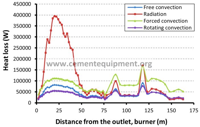
A view of cement rotary kiln in Aalborg Portland cement factory is seen in Fig. 1. The kiln length is 163 m and its outer diameter is 3.6 m for the 103 m initial length and 3.9 m for the rest. The temperature profile along the kiln, given by the cement factory is shown in Fig. 2(a). Moreover, a schematic view of the annular absorber designed around the kiln is inserted in this figure. Position interval for temperature measurement is 2 m. The free stream air temperature, T∞, and velocity, U∞, is assumed to be 278.15 K (5 ᵒC) and 5.86 m/s, respectively. The rotational speed of the kiln is 5 rpm clockwise. All properties of air are considered at film temperature. By finding the temperature distribution along the kiln length, heat transfer mechanisms including free convection, forced convection, radiation and convection due to rotation of the kiln can be calculated, as represented in Fig. 2(b), by using empirical and analytical correlations as expressed in [16, 17]. Previously, the authors showed that the rotating effect mixed by free convection from the kiln is significant and cannot be neglected [17]. This statement is confirmed in Fig. 2b. Moreover, the results emphasized that both free and forced convective heat transfer methods are significant, however radiative heat loss has the
main contribution among all the considered heat loss mechanisms. In this figure, different heat losses are shown for every 2 m of the kiln length. Kiln temperature about at 500 ᵒC is the highest temperature recorded along the kiln length, hence the highest heat loss from the kiln occurs in the domain corresponding to this temperature. Therefore, the positions near this temperature are the most relevant places and chosen for heat recovery purposes in this study. The total heat loss per unit length of the kiln at the temperature of 500 ᵒC is approximately 303 kW obtained by empirical correlations.

Fig. 1: A view of cement rotary kiln in Aalborg Portland cement factory, Aalborg, Denmark
(a)
(b)
Fig. 2: (a) Temperature distribution along the kiln and a schematic view of the annular absorber designed around the kiln; (b) Local heat loss from the kiln’s external surface.
Numerical study and verification
A numerical simulation is done to evaluate heat loss from the rotating kiln and find the body temperature of the absorber for waste heat recovery purpose. The kiln temperature is set to 773.15 K (500 ᵒC) and the free stream air temperature is maintained at 278.15 K (5 ᵒC). The cement kiln is considered as a circular cylinder of steel. Aluminum alloy sheet is chosen as the absorber since this alloy has high resistivity against oxidation in rainy weather condition. The inner diameter of the absorber is 4 m, whereas the cement kiln diameter is
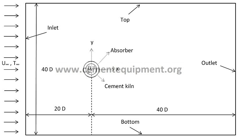
- m. Thickness of the circular absorber is 2.5 cm. Since the heat transfer mechanism is combination of different kinds of heat transfer, pattern of air flow, and diameters of kiln and absorber, magnitudes of Rayleigh and Reynolds number are great. Therefore, this problem is intrinsically turbulent [17]. The simulation has been carried out with a two dimensional (2D) unsteady solution. The calculation domain used for the investigation is shown in Fig. 3. The kiln center is placed at 20 D from the computational domain inlet. Width of the computational domain is set 40 D in order to realize the free stream condition at the top and the bottom boundaries. To eliminate impact of outflow boundary condition on the thermal features and fluid flow patterns in the wake region, the length of the computational domain between the center of the
cylinder and the outflow boundary is set 40 D. All boundaries of the rectangular domain are set to a fixed ambient temperature equal to 278.15 K (5 ᵒC).
Fig.3: Schematic view of 2D computational domain
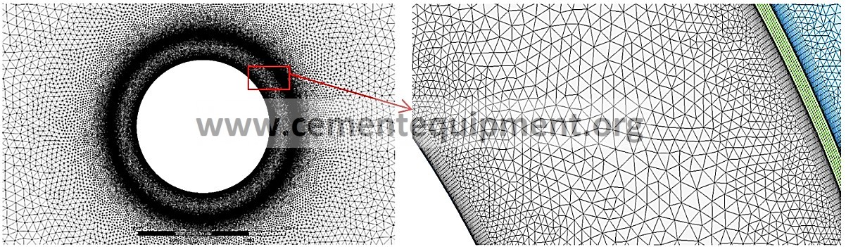
The radiative emissivity coefficient of the kiln shell is assumed 0.81, whereas it is considered 1.0 for the refractory painted absorber surface. Finite Volume Method (FVM) is used in this study by ANSYS Workbench package (R 17.2). In this software package, a CAD model is built in Design Modeler which is utilized as the geometric design software. ANSYS Meshing, as an integrated tool to ANSYS Workbench, is used for meshing. Several meshing algorithms are offered by meshing tool, where the applicability largely depends on the geometry and problem. Fluent tool is applied to solve the coupled governing equations of heat transfer and fluid flow. The post-processing is also done in CFD-Post and Microsoft Excel. In order to keep advantages of the k-ω and k-ε turbulence models, it is proposed to use the Shear-Stress Transport (SST) k-ω model. For radiation modelling, the surface to surface method (S2S) is chosen. View factor is one of the most effective parameters in this method [18-21]. Unstructured mesh is used for the numerical simulation in this study. Figure 4 shows construction of mesh in vicinity of the kiln and panel walls. The mesh dependence study was done to ensure accuracy of the results. More details on numerical simulation procedure can be found in the previous work by the authors [17] for arc shape absorber around the cement kiln.
- b)
Fig. 4: (a) A view of computational grid in ANSYS meshing tool, (b) A pattern of mesh around the kiln surface, absorber body and its walls
For verification of heat loss magnitudes obtained by numerical simulation, the cement kiln is considered in absence of the absorber. Analytical results are obtained by empirical correlations as explained in [17]. In order to better understanding of flow physics and heat transfer mechanism, both unsteady- and steady-state solutions are compared to the analytical solution when the kiln surface temperature is assumed 500 ᵒC. Table 1 compares the results between the numerical and analytical solutions.
Table 1: Different kinds of heat loss from the kiln per its unit length
Analytical
Radiation [kW]
Free convection [kW]
Forced convection [kW]
Rotational convection [kW]
Total convection [kW]
Total heat loss [kW]
solution
Numerical
Unsteady state model
182.49 39.32 54.66 26.62 120.59 303.08
182.47 ——– 63.39 245.86
solution Steady state model
182.47 ——– 57.67 240.14
Since there is no similar study in literature, verification of the heat loss from the kiln in the presence of the annular absorber is not considered. Although heat loss evaluation of the kiln could fundamentally be verified without considering the annular absorber effect. Moreover, there is no experimental result to assess the waste heat from the Aalborg Portland cement kiln. As it can be seen in verification section in [17], there were noticeable differences between the results of Nu number for Ra=100 and 100000 (low and mid-range Ra) in such simple case, namely free convection around a circular cylinder. In the present study, the heat transfer
mechanism and flow pattern are intrinsically complicated and the empirical correlations can estimate the heat transfer by lower accuracy. The radiative heat loss remains fairly constant for numerical and analytical solutions, whereas the reduction in the total heat loss in numerical solution is only due to reduction in its total convective heat transfer. Vortex shedding phenomenon affects the local features around the kiln in term of time, which causes periodic and transient behaviour. Hence, it can be concluded that, the unsteady simulation represents a better solution rather than the steady state. Heat transfer from the kiln surface in presence of the annular absorber is discussed in Section 6.

Mathematical model of the thermoelectric heat recovery system
By considering the symmetrical geometry of the TEG system and its thickness compared to the diameter of the annular absorber, the model can be built as one dimensional (1D) heat transfer under steady state conditions. For validation of the used model, a one dimensional FEM model code is developed in MATLAB software with the same design parameters as Dunham et al. [22] studied in their investigation. As shown in Fig. 5, a good agreement can be observed between results of this study and [22].
Fig. 5: Verification of FEM model results developed for TEG module
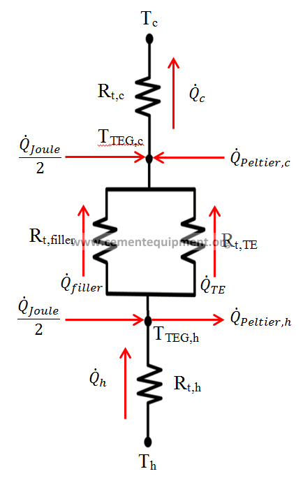
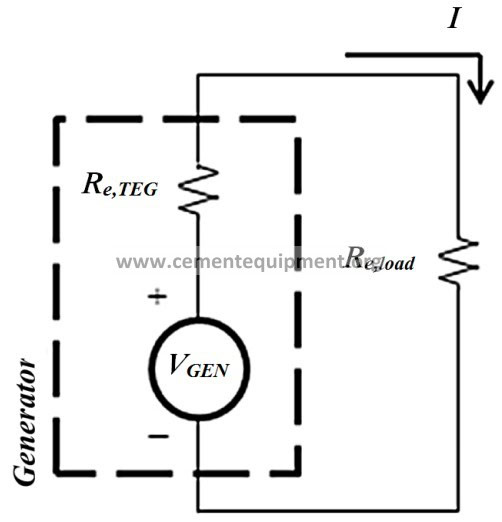
The thermoelectric unit around the outer surface of the panel is schematically illustrated in Fig. 6(a). A new model with radial heat flows is developed for the considered TEG as shown in Fig. 6(b). The thermal model equations are coupled to the electrical equations through the junction temperatures, and the thermal and electrical resistance networks are represented in Figs. 6(c) and 6(d).


- (b)
(c) (d)
Fig. 6: (a) Schematic view of the thermoelectric unit on the panel; (b) Vertically aligned TEG; (c) One dimensional thermal equivalent electrical circuit and (d) electrical resistance networks
The thermal resistance at the hot side of the TEG system is expressed by Rt,h that can be used for calculating the conductive heat transfer through ceramic substrate. Moreover, Rt,c, is thermal resistance at the cold side including conductive resistance of the ceramic substrate and thermal resistance to the ambient air around the panel. The model takes into account impacts of Peltier and Joule heating. Half of the Joule heating (QJoule), which is a volumetric generated heat, taken transferred to the hot side and the other half is conducted to the
cold side of the thermoelectric elements. The heat transfer between the cold and the hot junctions by the Peltier effect is expressed by QPeltier. A nodal energy balance at both hot and cold junctions can be given by [22]:
For hot junction:
𝑄ℎ ‒ 𝑄𝑇𝐸‒ 𝑄𝑓𝑖𝑙𝑙𝑒𝑟‒ 𝑄𝑃𝑒𝑙𝑡𝑖𝑒𝑟,ℎ +
𝑄𝐽𝑜𝑢𝑙𝑒
2 = 0
(1)
𝑄ℎ =
𝑇ℎ ‒ 𝑇𝑇𝐸𝐺,ℎ
𝑅𝑡,ℎ
(2)
𝑄𝑇𝐸=
𝑇𝑇𝐸𝐺,ℎ ‒ 𝑇𝑇𝐸𝐺,𝑐
𝑅𝑡,𝑇𝐸
(3)
𝑄𝑓𝑖𝑙𝑙𝑒𝑟=
𝑇𝑇𝐸𝐺,ℎ ‒ 𝑇𝑇𝐸𝐺,𝑐
𝑅𝑡,𝑓𝑖𝑙𝑙𝑒𝑟
(4)
𝑄𝑃𝑒𝑙𝑡𝑖𝑒𝑟,ℎ = 𝑛𝑆𝑇𝑇𝐸𝐺,ℎ 𝐼
(5)
2
𝑄= 𝐼
𝐽𝑜𝑢𝑙𝑒
𝑅𝑒,𝑡𝑜𝑡,𝑇𝐸𝐺
(6)
For cold junction:
𝑄𝑐‒ 𝑄𝑇𝐸‒ 𝑄𝑓𝑖𝑙𝑙𝑒𝑟‒ 𝑄𝑃𝑒𝑙𝑡𝑖𝑒𝑟,𝑐‒
𝑄𝐽𝑜𝑢𝑙𝑒
2 = 0
(7)
𝑄𝑐=
𝑇𝑇𝐸𝐺,𝑐‒ 𝑇𝑐
𝑅𝑡,𝑐
(8)
𝑄𝑃𝑒𝑙𝑡𝑖𝑒𝑟,𝑐= 𝑛𝑆𝑇𝑇𝐸𝐺,𝑐𝐼
(9)
In relation 2, Th is the average temperature of the panel’s external surface which is obtained from the numerical simulation. The hot and cold junctions temperatures are given by TTEG,h and TTEG,c, respectively. In these equations, the number of thermoelectric couple is shown by n, and the net Seebeck coefficient, S, is defined as Sp-Sn. Herein, Sp and Sn is the Seebeck coefficient of P-leg and N-leg material, respectively. The electrical current and total electrical resistance of the TEG module is I and Re,tot,TEG, respectively. The parallel thermal resistances of the filler and thermoelectric material are given by:
𝑅𝑡,𝑇𝐸= 𝑘
𝑇𝐸
𝑙𝑇𝐸
𝐴𝑡𝑜𝑡
𝐹𝐹
(10)
𝑅𝑡,𝑓𝑖𝑙𝑙𝑒𝑟= 𝑘
𝑓𝑖𝑙𝑙𝑒𝑟
𝑙𝑇𝐸
𝐴𝑡𝑜𝑡(1 ‒ 𝐹𝐹)
(11)
𝐴𝑡𝑜𝑡𝐹𝐹
𝑛=
2 𝐴
𝑙𝑒𝑔
𝑉𝑔𝑒𝑛= 𝑛𝑆(𝑇𝑇𝐸𝐺,ℎ ‒ 𝑇𝑇𝐸𝐺,𝑐)
(12)
(13)
𝐼= 𝑅
𝑉𝑔𝑒𝑛
𝑒,𝑡𝑜𝑡, 𝑇𝐸𝐺+ 𝑅
𝑒,𝑙𝑜𝑎𝑑
(14)
𝑅𝑒,𝑇𝐸𝐺= 2 𝑛𝜌𝑇𝐸(
𝑙𝑇𝐸)
(15)
𝐴𝑙𝑒𝑔
𝑅𝑒,𝐼𝐶= 2 𝑛𝜌𝐼𝐶
1
𝐹𝐹+ 1
𝑡𝐼𝐶
(16)
𝑅𝑒,𝑐𝑜𝑛𝑡𝑎𝑐𝑡= 4 𝑛
𝜌𝑐𝑜𝑛𝑡𝑎𝑐𝑡
𝐴𝑙𝑒𝑔
(17)
𝑅𝑒,𝑡𝑜𝑡,𝑇𝐸𝐺= 𝑅𝑒,𝑇𝐸𝐺+ 𝑅𝑒,𝐼𝐶+ 𝑅𝑒,𝑐𝑜𝑛𝑡𝑎𝑐𝑡
(18)
where lTE is the thermoelectric leg length, kTE and kfiller are the thermal conductivities of the thermoelectric material and filler material (air), respectively. The area of each thermoelectric leg is expressed by Aleg. The Seebeck voltage is defined by Vgen. The electric current, namely I, is calculated by dividing the generated Seebeck voltage into the electrical resistance of the total pathway through the generator and load. The electrical resistivity of thermoelectric material, interconnections, and contacts are represented by ρTE, ρIC, and ρcontact, respectively. These values are used for calculating the different electrical resistances. Due to annular shape of the thermoelectric heat recovery system around the panel, surface area of each section in the calculations changes with a local diameter. Therefore, Atot is the average area between top and bottom device footprint areas, and FF is fill factor of active thermoelectric material in Atot. Parameters DR-t,h and DR-t,c are the local diameters that are used for heat conduction calculations through inner and outer ceramic substrates. D0 denotes external diameter of the absorber. Parameters lsub,i and lsub,e are inner and outer substrates thicknesses. The thermal conductivity of substrate material is represented by ksub,i and ksub,e, respectively for internal and external substrate. As mentioned above, Rt,c expression has two parts, the first one relates to heat conduction through the outer substrate and the second one relates to heat transfer to the ambient by
convection. For obtaining the convection area, Aout corresponding to Dout is defined. Here, hc is the average heat transfer coefficient around the outer surface of the panel, which is obtained from the numerical simulation.
𝐷𝑅
𝐴𝑅
𝑡,ℎ
= 𝐷0 + 𝑙𝑠𝑢𝑏,𝑖
= 𝜋𝐷𝑅
(19)
(20)
𝑡,ℎ
𝑡,ℎ
𝑅𝑡,ℎ = 𝑘
𝑙𝑠𝑢𝑏,𝑖
𝐴
(21)
𝑠𝑢𝑏,𝑖
𝑅𝑡,ℎ
𝐷𝑅
𝐴𝑅
𝑡,𝑐
= 𝐷0 + 2 𝑙𝑠𝑢𝑏,𝑖+ 2 𝑙𝑇𝐸+ 𝑙𝑠𝑢𝑏,𝑒
= 𝜋𝐷𝑅
(22)
(23)
𝑡,𝑐
𝑡,𝑐
𝐷𝑜𝑢𝑡= 𝐷0 + 2 𝑙𝑠𝑢𝑏,𝑖+ 2 𝑙𝑇𝐸+ 2 𝑙𝑠𝑢𝑏,𝑒
𝐴𝑜𝑢𝑡= 𝜋𝐷𝑜𝑢𝑡
(24)
(25)
𝑅𝑡,𝑐= 𝑘
𝑙𝑠𝑢𝑏,𝑒
𝐴
1
+ ℎ 𝐴
(26)
𝑠𝑢𝑏,𝑒
𝑅𝑡,𝑐
𝑐𝑜𝑢𝑡
𝐴𝑡𝑜𝑡= 𝜋(𝐷0 + 2 𝑙𝑠𝑢𝑏+ 𝑙𝑇𝐸)
(27)
Maximum power by the thermoelectric device occurs when the external electrical load is equal to the internal electrical resistance of the thermoelectric unit [23-26]. The power is therefore named as matched power output. The coupled system of Equations (1-27) requires an iterative solution to find the temperatures on the hot and cold junctions of the generator. By assuming a same external load and then revealing the unknown temperatures at both hot and cold junctions, the matched power output can be obtained by using the first law of Thermodynamic [27]. Equation 28 is applicable in this study, because radiative and convective heat losses from the thermoelectric elements to the neighbor elements and ambient are neglected.
𝑃𝑀𝑎𝑡𝑐ℎ𝑒𝑑= 𝑄ℎ ‒ 𝑄𝑐
(28)
Bi2Te3 and Zn4Sb3 are considered as the thermoelectric materials for performance comparison in this study. For p- and n-type of these materials, the thermo-electrical properties such as thermal conductivity,
electrical resistivity, and Seebeck coefficient are assumed identical, where the Seebeck coefficient has a positive sign for the p-legs and a negative sign for the n-legs [28-30]. Properties of the considered thermoelectric materials are temperature dependent. Nominal parameters applied to produce modelling results are given in Table 2.
Table 2: Assumed parameters for mathematical modelling
Diameter of the kiln 3.6 m
Outer diameter of the absorber (D0) 4.05 m
Absorber thickness 2.5 cm
Absorber width 1 m
Internal and external substrate thickness (lsub,i and lsub,e) 1 mm
Thermal conductivity of substrate (ksub,i and ksub,e) 30 W/mK
Thermal conductivity of filler (kfiller) 0.024 W/mK
Cold reservoir temperature, ambient air (Tc) 278.15 K
Average temperature on the absorber external surface (Th) 592.4395 K
Individual leg cross sectional area (Aleg) 4×10⁻⁶ m2
Average convective heat transfer coefficient around the panel external surface (hc) 31.7194 W/m2K Semiconductor/metal electrical contact resistivity (ρcontact) 5×10-11 Ωm2
Au interconnect thickness (tIC) 100 μm
Electrical resistivity of interconnections (ρIC) 2.44×10⁻⁸ Ωm
The temperature dependent properties of the thermoelectric materials such as Seebeck coefficient (α), thermal conductivity (k), and electrical resistivity (ρ) for both Bi2Te3 and Zn4Sb3 are given by polynomials equations. Their coefficients are observed in Table 3.
Table 3: Constants of polynomial equations (a3T3+a2T2+a1T+a0), representing the material properties of Bi2Te3 and Zn4Sb3 [28-30].
| Bi2Te3 | ||||
| a3 | a2 | a1 | a0 | |
| α (V/K) | 0 | -1.6×10⁻⁹ | 1.0023×10⁻⁶ | 6.2662×10⁻⁵ |
| k (W/mK) | 0 | 9×10⁻⁶ | -1.3×10⁻³ | 9.752×10⁻¹ |
| ρ (Ωm) | 0 | -2×10⁻¹⁰ | 1.94×10⁻⁷ | -3.525×10⁻⁵ |
| Zn4Sb3 | ||||
| a3 | a2 | a1 | a0 | |
| α (V/K) | 0 | -6×10⁻¹⁰ | 8.08×10⁻⁷ | -9.52×10⁻⁵ |
| k (W/mK) | 0 | 0 | -1.3×10⁻⁴ | 8.6×10⁻¹ |
| ρ (Ωm) | -5×10-13 | 5×10⁻¹⁰ | -1.47×10⁻⁷ | 2.465×10⁻⁵ |
Economic evaluation
To find optimal design of the TEG system, one demand can be achieving maximum generated power. On the other hand, according to importance of economic aspect, consideration of power generation and investment cost simultaneously is necessary [31-41]; therefore, total cost per power ratio ($/W) is introduced in this section. For an efficient system, this ratio should be minimized, so the TEG system generates its relative maximum power versus minimum total investment cost. Different types of cost in economic evaluation of a thermoelectric system have been considered previously [42-49]. In this article, various cost contributions are extracted from the previous studies, and are utilized for more accurate cost estimation.
Main costs of a TEG system include bulk raw material cost (CB), ceramic substrate cost (CC), areal manufacturing cost (CM,A), manufacturing cost associated with processing bulk material (CM,B), heat exchanger cost (CH-EX), balance of system cost (CBoS) and installation cost (CI). To build a bulk TEG module using Zn4Sb3 and Bi2Te3, dicing (D), metallization (M), medium level microfabrication (MLM) and screen printing (SP) are implemented as areal manufacturing processes, and spark plasma sintering (SPS) is used as the only bulk material manufacturing process in this study. CH-EX is not counted since there is no heat exchanger in the present design. One of the main advantages of solid-state TEG systems is that there is no need to essential maintenance after installation. Accordingly, the maintenance and operation cost is usually negligible. Total cost of TEG system in this study is formulated as follows:
𝐶𝑡𝑜𝑡= 𝐶𝐵+ 𝐶𝐶+ 𝐶
𝑀,𝐵
+ 𝐶𝑀,𝐴+ 𝐶𝐵𝑜𝑆+ 𝐶𝐼
(29)
𝐶= 𝐶∗ (2𝑛𝜌𝑙𝐴)
𝐵𝐵𝑇𝐸𝑙𝑒𝑔
(30)
𝐶𝐶= 𝐶𝐶(𝐴𝑅
∗
+ 𝐴𝑅)
(31)
𝑡,ℎ
∗
𝑡,𝑐
∗
𝐶𝑀,𝐵= 𝐶𝑀,𝐵(2𝑛𝜌𝑙𝑇𝐸𝐴𝑙𝑒𝑔) = 𝐶𝑆𝑃𝑆(2𝑛𝜌𝑙𝑇𝐸𝐴𝑙𝑒𝑔)
(32)
𝐶𝑀,𝐴= 𝐶𝑀,𝐴(2𝑛𝐴𝑙𝑒𝑔) = (𝐶
+ 𝐶𝑀+ 𝐶𝑀𝐿𝑀+ 𝐶𝑆𝑃)(2𝑛𝐴𝑙𝑒𝑔)
(33)
∗ ∗ ∗ ∗ ∗
𝐷
𝐶𝐵𝑜𝑆= 0.1 (𝐶𝐵+ 𝐶𝑀,𝐵+ 𝐶𝑀,𝐴+ 𝐶𝐶)
𝐶𝐼= 0.1 (𝐶𝐵+ 𝐶𝑀,𝐵+ 𝐶𝑀,𝐴+ 𝐶𝐶)
∗
(34)
(35)
where 𝐶𝐵is the average price per unit mass of the typical bulk thermoelectric materials, $110/kg for Bi2Te3,
and $4/kg for Zn Sb ; 𝐶∗
4 3 𝐶
𝑀,𝐵
is the ceramic substrate cost per unit sheet area, $1000/m2;
𝐶∗ is the bulk
material processing cost per unit mass of thermoelectric materials, herein only including 𝐶∗ , which is equal
𝑆𝑃𝑆
to $1.3/kg. Parameter 𝐶∗
𝑀,𝐴
is expressed the areal manufacturing cost per unit area of the TEG module. The
specific areal cost consists of dicing cost per unit area (𝐶∗ ), $47/m2; metallization cost per unit area (𝐶∗ ),
𝐷
$120/m2; medium level microfabrication cost per unit area (𝐶∗
𝑀
), $2500/m2; and screen printing cost per
unit area (𝐶∗ ), $4.8/m2.
𝑆𝑃
𝑀𝐿𝑀
Balance between the system cost and installation cost are separately considered as 10 % of the TEG system
cost. Parameter ρ is average density of the selected thermoelectric materials, 6115 and 7740 kg/m3, for Zn4Sb3 and Bi2Te3, respectively.
Results and discussions
- Heat transfer analysis in presence of annular absorber
According to the physics of flow in combined free and forced convection, formation of vortex shedding around the absorber body occurs. Therefore, the unsteady solution based on real flow pattern offers a better result than the steady state solution. In this study, after converging of solution, the results are drawn from the CFD-Post. In the absence of the absorber, the kiln can freely transfer the heat to its surrounding. The annular absorber locally increases the thermal resistance around the kiln surface, and the amount of heat loss is reduced. According to the numerical results, total heat transfer from unit length of the kiln in presence of the annular absorber is124.779 kW. Compared to the results in Table 1, total heat loss decreases via utilizing the annular absorber by 50 % because of insulation effect of the annular absorber.
In Fig. 7, instantaneous contour of air temperature around the absorber and kiln is shown at a fixed time. Moreover, it shows temperature contour at cross section of the absorber. The periodic wake flow does not have a strong effect on average heat transfer features at different times after fully convergence, and its impact is reasonably neglected on the absorber temperature distribution. By using the time averaged temperature distribution along the absorber circumference, the average temperature of the kiln is calculated and used as the hot side temperature of the thermoelectric unit in the model. The average temperature is 592.44 K. Furthermore, the average heat transfer coefficient around the outer surface of the absorber is obtained as
31.72 W/m2K which is applied at the cold side boundary condition in the mathematical model based on FEM.
Fig. 7: Temperature contour around the outer surface of the kiln; between the kiln and absorber; and at cross section

of the absorber body
- Thermoelectric junctions temperature difference and the temperature efficiency
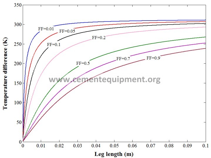
The governing equations are solved by an iterative solution to achieve the results. In Figs. 8(a) and 8(b), temperature difference between the thermoelectric junctions is shown for both thermoelectric materials, Bi2Te3 and Zn4Sb3. By increasing the leg length, the temperature difference increases, whereas by increasing the fill factor, it decreases. In lower fill factors, the temperature difference increases more rapidly and then maintains almost constant, despite for higher fill factors this trend cannot be observed in the studied range of leg length. Also, based on Eq. (10), by increasing the fill factor, the total thermal resistance of the TEG device is decreased. Therefore, the temperature difference between two thermoelectric junctions reduces. Higher variation of temperature difference for bismuth telluride in comparison with zinc antimonide in the studied range of fill factor and leg length indicates higher value of thermal conductivity of Bi2Te3 than Zn4Sb3.


- (b)
(c) (d)
Fig. 8: Temperature difference between the thermoelectric junctions at peak power output, (a) Bi2Te3, (b) Zn4Sb3; Temperature efficiency, (TTEG,h-TTEG,c)/(Th-Tc), at peak power output, (c) Bi2Te3, (d) Zn4Sb3.
The ratio of temperature drop between two thermoelectric junctions, (TTEG,h-TTEG,c), to the total temperature difference from the hot and the cold reservoirs, (Th-Tc), is less than unity for non-zero heat sink and source thermal resistances and is expressed as temperature efficiency that can be useful for TE device analysis. The temperature efficiency is demonstrated in Figs. 8(c) and 8(d) for two materials versus different values of fill factors and leg lengths. There are similar explanations for the trend of Figs. 8(a, b) and Figs. 8(c, d). In the case without thermal resistance between the thermal reservoirs and the thermoelectric junctions, the temperature efficiency approaches 1.0 and the temperature difference between junctions is as same as the reservoirs temperature difference. In the case with external thermal resistance much greater than the TEG’s
and filler’s thermal resistance, the junctions temperature difference and, consequently, the temperature efficiency approaches zero, because main part of the temperature drop occurs across the external resistances.
- Matched power output and energy conversion efficiency
In Figs. 9(a) and (b), effect of variation of the leg length and fill factor can be seen on the matched power output by considering two different thermoelectric materials. For all fill factors, the power quickly rises up by increasing the leg length to a maximum level, and then decreases. In an ideal thermoelectric system, the maximum matched power is achieved when half of the temperature difference between the hot and cold reservoirs occurs between the two thermoelectric junctions. Nevertheless, when resistance of interconnect is taken into account, as it is included in this study, the fractional temperature difference is changed, and the matched power output occurs at a longer leg length. It may seem that a high fill factor is desirable for efficient use of TEG device; however it is observed that it is not desirable design to maximize the power output unless the thermo-elements are taken long. Maximum of peak power output occurs at each fill factor for an individual leg length. Moreover, for short legs, this optimum fill factor approaches zero. For longer legs, the maximum of peak power would occur in higher fill factors. Under this condition, the electrical resistance of the TEG module is too large to reach the peak power output with any fill factor over the studied range of leg length.
If the Peltier heat impact would not be taken into account in the equations, the optimal leg length would not dependent on temperature difference at any fill factor. For high temperature differences along the thermoelectric legs, temperature dependent properties can become important factor in the power generation. It must be mentioned that in this study, the thermoelectric material properties are considered as temperature dependent. As shown in Fig. 9(b), for instance, this recovery unit can produce a power about 3.564 kW (≈
0.28 kW per unit area of the absorber, kW/m2) for fill factor and leg length of 0.2 and 7.7 mm, respectively. This power can be increased up to 3.939 kW (≈ 0.309 kW/m2), when the fill factor and leg length are taken
- and 32.4 mm. It seems the fill factor of 0.2 and the leg length 7.7 mm is more efficient economically in comparison with the fill factor of 0.9 and the leg length 32.4 mm, because, while the power difference between the two mentioned cases is not so much, producing cost dependent on volume of used material is
much higher for the second case. By substituting Bi2Te3 as p- and n-legs, the module can generate power
equal to 1.784 kW (≈ 0.14 kW/m2) since the fill factor is 0.2 and the leg length is 37.7 mm. Consequently, zinc antimonide thermoelectric material can generate about two times more power with one fifth of Bi2Te3 leg length at fill factor 0.2.
The matched power output and the inlet heat flow rate, Qh, individually for each case, are used to calculate the energy conversion efficiency in the present model. In Figs. 9(c) and (d), the variation of the thermoelectric energy conversion efficiency is represented based on the leg length for various fill factors at matched electrical load. As can be seen, the efficiencies of the TEG systems are quite different from each other due to using different thermoelectric materials. The results represent that Zn4Sb3 has higher efficiency when the leg length and fill factor become large.


- (b)
(c) (d)
Fig. 9: Matched power output versus fill factor and leg length, (a) Bi2Te3, (b) Zn4Sb3; Energy conversion efficiency at peak power output, (c) Bi2Te3, (d) Zn4Sb3.
- Thermoelectric couple number
According to Eq. (12) and (27), the number of thermoelectric couples is a function of leg length due to annular shape and radial design of the thermoelectric unit. Therefore, the distribution of the number of the couples is a linear function of thermoelectric leg length. In other word, by increasing the leg length in a fixed fill factor, the couple number increases slightly. In Fig. 10, the number of couples versus leg length is represented. The figure can be used for both thermoelectric systems. It should be noted that the number of couples corresponding to maximum matched power output at a fixed fill factor is different for systems designed with different materials. For instance in fill factor of 0.2, the optimal leg length corresponding to maximum peak power for Bi2Te3 based TE system is 37.7 mm, hence the couple number becomes 321204 (25245 couple over the absorber unit area). On the other hand, by using Zn4Sb3, the couple number is obtained to be 318848 (25060 couple over the absorber unit area) which calculated from the optimal leg length (7.7 mm) individually corresponding to its maximum matched power output.
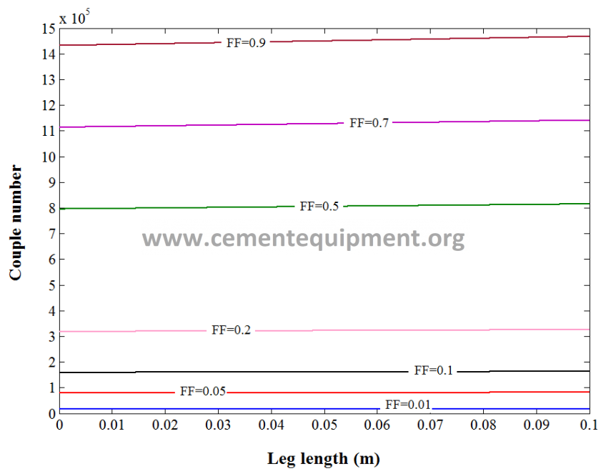
Fig. 10: Thermoelectric couple number versus leg length at peak power output for both Bi2Te3 and Zn4Sb3.
- TEG system optimization
By using Eqs. 29-35, the total investment cost for two systems are calculated. The price of raw material has
an important role in economic evaluation and cost of the systems. The bulk Bi2Te3 material, per unit mass, is taken 27.5 times more expensive than the Zn4Sb3 material. Furthermore, to obtain the maximum peak power output at a fixed fill factor, thermoelectric legs of bismuth telluride modules should be several times longer than that one in zinc antimonide module. Based on the present economic evaluation, ceramic substrate cost has the highest contribution in the total cost.
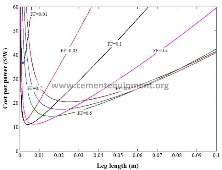
Comparing the results of Fig. 11(a) and 11(b) shows great differences between the costs of two systems. By increasing the leg length, the total cost changes approximately with a linear trend, however the slope of the variation depends on the magnitude of fill factor. The incremental trend is amplified for higher fill factors. In order to find an optimal TEG system, ratio of the cost per power is used, because the best design from power generation aspect possesses the highest fill factor and the highest leg length, nevertheless the investment cost extremely increases and is not economically reasonable. In Fig. 11(c) and 11(d), this ratio is shown for a wide range of leg length and fill factor for Bi2Te3 and Zn4Sb3. The minimum point of each curve indicates leg length corresponding to the lowest cost per power ratio in an individual fill factor.
The lowest ratio between the minimum points determines the optimum properties of the TEG system by the double-objective optimization, although these properties usually do not result to the highest power
generation. For Bi2Te3, the lowest ratio of cost per power is 25.44 $ W and occurs at fill factor of 0.05 and
leg length of 8.8 mm. The optimum leg length corresponding to maximum peak power output in the same fill
factor is equal to 10.8 mm. For Zn4Sb3, the lowest cost per power ratio is 10.98 $ W and occurs at fill factor
of 0.1 and leg length of 4.2 mm, while the maximum peak power related to this fill factor is obtained at leg
length of 4.3 mm. Therefore, the leg length which minimizes cost per power ratio is different from the leg length that maximizes peak power output. Moreover, the optimum leg length obtained by analysing cost per power ratio is shorter than the leg length corresponding to the maximum peak power output at a fixed fill factor.


- (b)
(c) (d)
Fig. 11: Total cost versus fill factor and leg length at peak power output, (a) Bi2Te3, (b) Zn4Sb3; Cost per power ratio at peak power output, (c) Bi2Te3, (d) Zn4Sb3.
In Table 4, information about fill factor, total investment cost, matched power output, cost per power ratio, payback period and leg length corresponding to the optimum design is mentioned for two thermoelectric systems. If the cement kiln works continuously during a year, with 8760 h working hours, and with assumption of electricity price for household consumption in Denmark [50] equal to $0.35/kWh the optimum Bi2Te3 TEG system should operate at least 8.30 years to repay its primary investment cost. However, the optimum Zn4Sb3 TEG system shows that its payback period is 3.58 years. After these periods, the recovery systems can be profitable.
Table 4: Optimum design properties (based on cost per power) for Bi2Te3 and Zn4Sb3 TEG systems
| Bi2Te3 | ||||||
| Lopt | PPPopt | PPPopt | Cost | Cost per power | Payback period | |
| FFopt (mm) | (W) | (W/m2) | ($US) | ($US/W) | (year) | |
| 0.01 4 | 825.033 | 64.844 | 31517 | 38.2 | 12.46 | |
| 0.05 8.8 | 1511.9 | 118.828 | 38465 | 25.44 | 8.30 | |
| 0.1 12.4 | 1573.5 | 123.669 | 51106 | 32.48 | 10.59 | |
| 0.2 16.7 | 1430.4 | 112.422 | 83007 | 58.03 | 18.93 | |
| 0.5 26 | 1110.7 | 87.296 | 223460 | 201.2 | 65.62 | |
| 0.7 31 | 992.299 | 77.99 | 347320 | 350.012 | 114.16 | |
| 0.9 36.1 | 922.405 | 72.496 | 499240 | 541.24 | 176.53 | |
| Zn4Sb3 | ||||||
| 0.01 | 1.6 | 855.6 | 67.246 | 30980 | 36.21 | 11.81 |
| 0.05 | 2.6 | 2558 | 201.046 | 32677 | 12.77 | 4.17 |
| 0.1 | 4.2 | 3175.1 | 249.547 | 34877 | 10.9845 | 3.58 |
| 0.2 | 7.5 | 3564 | 280.113 | 39530 | 11.09 | 3.62 |
| 0.5 | 16 | 3818.8 | 300.139 | 55136 | 14.44 | 4.71 |
| 0.7 | 21 | 3861 | 303.456 | 66743 | 17.29 | 5.64 |
| 0.9 | 25.2 | 3867.9 | 303.997 | 79000 | 20.424 | 6.66 |
The previous studies on heat recovery from the kiln [13-15] concluded that the recovery systems can produce peak power output of 107.15 W/m2 (by Bi2Te3 modules), 186.57 W/m2 (by combination of Bi2Te3 and PbTe modules), and 312.635 W/m2 (unknown materials), respectively, which are comparable with the results of the present study in Table 4. This system could save energy in two ways. The assembled annular absorber and the TEG system, particularly due to low thermal conductivity of thermoelectric materials, reduced the heat loss due to its insulation effect. Furthermore, the TEG system could convert a fraction of heat loss from the kiln external surface directly into electricity. In the rotary kilns, balance of the surface temperature is an important variable affecting cement quality. Therefore, the recovery system in this study was only designed for unit length of the annular absorber to minimize its effect on the cement producing process.
Conclusions
The aim of the present study was to design and optimize a radial TEG system innovatively for waste heat recovery from the cement kiln. In order to fulfil this objective, by a comprehensive numerical simulation, boundary conditions for designing a thermoelectric unit on the outer surface of the annular panel were determined. A mathematical model was developed to design a thermoelectric unit and to estimate performance of the waste heat recovery system. The results show that, the double-objective optimization represented that Zn4Sb3 based thermoelectric unit by assuming fill factor of 0.1 can generate electrical power
approximately 3.17 kW (≈ 0.25 kW/m2), while Bi2Te3 based thermoelectric unit with the fill factor of 0.05 can produce 1.51 kW (≈ 0.119 kW/m2). The results indicated that, although investment cost of the bismuth telluride TEG unit is much higher than the zinc antimonide based TEG unit, zinc antimonide module generates more electrical power with higher energy conversion efficiency. Moreover, the investment cost payback period of the Bi2Te3 TEG system was obtained 8.30 years, while it is 3.58 years for the Zn4Sb3. Therefore, the Zn4Sb3 based TEG system is better candidate for waste heat recovery around the rotary cement kiln. The thermoelectric waste heat recovery is a promising technology by developing innovative strategies for design optimization besides high performance and low price thermoelectric materials.
Acknowledgment
This work has been carried out within the framework of the Center for Thermoelectric Energy Conversion (CTEC) and funded in part by the Danish Council for Strategic Research, Programme Commission on Energy and Environment, under Grant No. 1305-00002B.
References
[1] Engin T, Ari V. Energy auditing and recovery for dry type cement rotary kiln systems- a case study. Energy Convers Manage 2005;46:551–562.
[2] Mirolli MD. The Kalina cycle for cement kiln waste heat recovery power plants. Cement Industry
Technical Conference, 2005, Kansas City, MO, USA. DOI: 10.1109/CITCON.2005.1516374.
[3] Zhang G, Zhu G, Wang C. A New application of waste heat recovery power generation in clinker kiln.
Cement Industry Technical Conference, Conference Proceeding: IEEE, 2009, Palm Springs, CA, USA, DOI: 10.1109/CITCON.2009.5116162.
[4] Söğüt Z, Oktay Z, Karakoç H. Mathematical modeling of heat recovery from a rotary kiln. Appl Therm Eng 2010;30:817–825.
[5] Karellas S, Leontaritis AD, Panousis G, Bellos E, Kakaras E. Energetic and exergetic analysis of waste heat recovery systems in the cement industry. Energy 2013;58:147-156.
[6] Ayu TT, Hailu MH, Hagos FY, Atnaw SM. Energy audit and waste heat recovery system design for a
cement rotary kiln in Ethiopia: A case study. Int J Automot Mech Eng 2015;12:2983-3002.
[7] Bayuaji R, Biyanto TR, Irawan S. Design of cement plant waste heat recovery generation. Power Engineering Conference (AUPEC), 2015, Wollongong, Australia, DOI: 10.1109/AUPEC.2015.7324816.
[8] Bundela PS, Chawla V, Sustainable development through waste heat recovery. Am J Environ Sci 2010;6 (1):83-89.
we are thinking to implement this to ambuja cement ., i want contact of the suppliers so that we can go further
Dear Sir,
I am interested in knowing name of companies who undertake such project of waste heat recovery from cement Kiln.It will help in reducing fuel consumption.Pls forward details so that we can approach them.
regards