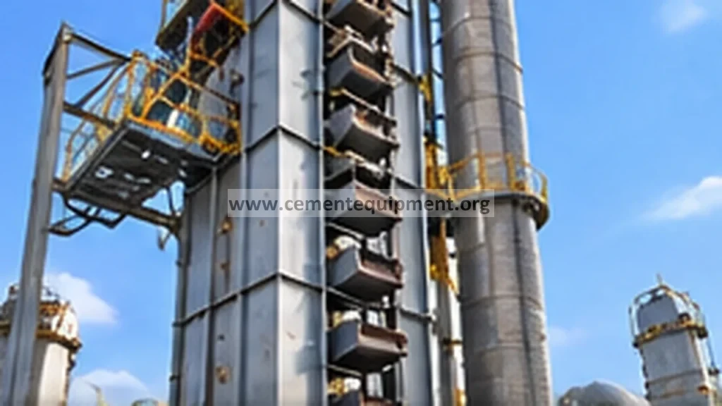

Casing rubbing is evidence of relative movement between the bucket line and the elevator casing, not a reason to increase tension blindly. First map the contact location and direction, then inspect belt or chain tracking, bucket damage, pulley or sprocket alignment, take-up freedom, casing straightness and feed distribution. Correct the cause that moves the bucket path off center, then verify a clean no-contact run under stable loading.
Stop recurring bucket-to-casing contact without creating excess belt, chain, bearing or shaft load.
Use rub marks, noise location, tracking position, bucket condition, pulley or sprocket alignment, take-up travel and loading pattern.
Separate tracking, mechanical alignment, damaged-bucket, take-up and feed-distribution causes before adjustment.
Capture evidence before adjustment
Record where the rubbing is heard and where polished metal, paint removal, dust streaks or bucket-edge marks appear. Note whether contact is on the ascending or descending leg, near the boot, head, inspection doors or one intermediate casing section. Record belt or chain position, take-up position, feed rate, recent maintenance, splice or chain work, bucket replacements and whether the symptom changes between empty and loaded running.
Preserve the as-found condition until the contact pattern is understood. Random tracking or tension adjustments can erase the evidence and move the rub to another location.
1. Localize the contact zone safely
Use external sound, inspection openings available under the plant’s isolation procedure, and visible rub evidence to identify the contact zone. Do not reach into or open unsafe access points on a running elevator. Distinguish continuous rubbing from intermittent strikes. Continuous contact often points toward sustained mistracking or casing geometry; periodic impact can indicate a bent bucket, loose fastener, splice irregularity or local deformation.
2. Inspect the bucket line and attachment condition
With the elevator safely isolated, inspect buckets around the suspected zone. Look for bent lips, cracked or distorted buckets, loose fasteners, missing hardware and evidence that one bucket projects farther than its neighbors. On belt elevators, inspect the belt and splice for distortion. On chain elevators, inspect chain links, attachments and bucket mounting for unequal geometry. Repair physical defects before attempting to tune tracking around them.
3. Check belt or chain tracking through the boot and head
Observe the running position using the machine’s approved inspection method. Determine whether the carrying element consistently favors one side or wanders. A stable side bias suggests alignment, loading or pulley/sprocket geometry. Wandering can point toward unstable feed, contamination, take-up behavior, damaged belt or chain components, or changing friction conditions. Compare head and boot behavior instead of assuming the first visible off-center point is the root cause.
4. Verify pulley, sprocket and shaft alignment
Check the head and boot rotating elements against the equipment’s alignment procedure. Inspect bearings, housings, shaft seating and structural supports for movement or looseness. For belt elevators, inspect pulley lagging and buildup that can alter effective geometry. For chain elevators, inspect sprocket wear and chain engagement. Use the OEM’s specified alignment and tension criteria rather than generic field tolerances.
5. Inspect take-up freedom and symmetry
A take-up that binds, moves unevenly or reaches a mechanical limit can force the bucket line away from its intended path. Inspect guides, screws, weights, slides and structural contact as applicable. Compare both sides for free and symmetric movement. Do not use additional tension as a substitute for a seized guide or misaligned take-up assembly; excessive tension can transfer the problem into bearings, shafts, belt splice or chain components.
6. Check feed entry and boot loading
Uneven or surging feed can push buckets laterally or overload one side of the boot. Inspect chute condition, buildup, gate position and material trajectory. Confirm that material is entering the elevator as intended and that boot cleanup is effective. If rubbing appears only at high feed, compare the loaded and unloaded tracking positions and investigate feed distribution before changing mechanical alignment.
7. Check casing geometry and support condition
If the bucket path is centered at the head and boot but contact remains localized in one casing section, inspect that section for distortion, shifted flanges, loose supports or installation misalignment. A casing can move relative to a correctly tracked bucket line. Use plant drawings and the elevator manufacturer’s erection checks where available. Correct structural causes rather than forcing the rotating path to follow a distorted casing.
Bucket elevator rubbing decision table
| Observed pattern | Likely direction | Priority evidence |
|---|---|---|
| Periodic strike at one repeat interval | Damaged bucket, attachment or splice/chain irregularity | Mark the cycle and inspect corresponding components |
| Continuous rub on one side | Tracking or alignment bias | Head/boot position, pulley or sprocket alignment, take-up symmetry |
| Rub only under high feed | Feed distribution or boot loading | Chute trajectory, buildup, surge and loaded tracking |
| Localized rub with centered head and boot | Casing/support geometry | Intermediate casing straightness, flange and support condition |
Common mistakes and repeat-failure traps
- Increasing tension before checking whether the take-up can move freely.
- Adjusting tracking without documenting which casing side is being contacted.
- Ignoring one bent bucket because the belt or chain appears generally centered.
- Correcting the bucket path to compensate for a distorted casing section.
- Checking only empty running when the rub occurs under material load.
- Using unsupported generic alignment tolerances instead of the installed elevator OEM criteria.
Verification and return-to-service criteria
After corrective work, verify that all guards, inspection covers and safety devices are restored. Confirm the bucket line remains stable through the approved observation points, the take-up operates within its normal working range, and there is no recurring contact sound or fresh rub evidence. Run through the plant’s normal loading sequence and verify that tracking remains stable as feed increases. Reinspect the previous contact zone after the defined observation period. Return to normal service only when the machine runs without bucket-to-casing contact and the corrected condition remains repeatable under representative load.
Related Infinity technical guides
References and engineering limits
Use the installed bucket elevator manufacturer’s manual for belt or chain tension, pulley or sprocket alignment, take-up setting, fastener torque, inspection intervals and acceptance limits. Plant isolation and guarding procedures govern all physical inspection work. This troubleshooting sequence deliberately avoids invented universal tolerances because elevator geometry and allowable settings depend on the installed design.