Quick answer
If a centralized lubrication pump runs but grease does not reach a bearing, diagnose the distribution path rather than assuming pump failure. Check reservoir level, pump outlet pressure, main-line relief, progressive divider operation, blocked injectors, broken/leaking lines, wrong grease consistency and whether the bearing fitting is blocked. A running motor only proves the pump drive is active—not that lubricant is being delivered to every point.
Problem / job
Automatic lubrication cycles normally, but one or more bearings remain dry or show rising temperature/vibration.
Evidence
Capture pump outlet pressure, cycle indicator, grease level/type, divider/injector movement, line leakage and bearing-point condition.
Decision
Separate pump/no-reservoir issues from blocked divider valves, broken lines, incompatible grease and blocked bearing fittings.
As-found evidence capture
Do not start by disconnecting random grease lines. Record reservoir level, grease product/grade, pump cycle status, pump outlet pressure, pressure-switch behavior, relief-valve activity and any system fault code or divider-cycle indication. Note whether one lubrication point, one branch or all points are affected; that pattern is one of the fastest ways to localize the failure.
Inspect for obvious external leakage, crushed tubing, disconnected fittings and recently changed grease. If the failure began after refilling, service work or a grease change, preserve that change history. Before opening any component, isolate the machine and lubrication pump, apply the site lockout/tagout procedure, and verify stored grease pressure has been relieved by the OEM-approved method. Never loosen a live fitting or use a hand to locate a suspected leak: high-pressure grease can penetrate skin. Suspected grease-injection injuries require immediate emergency medical assessment, even when the visible puncture appears minor.
First identify the lubrication-system type
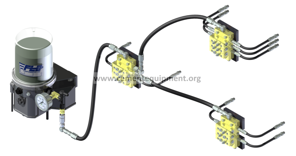
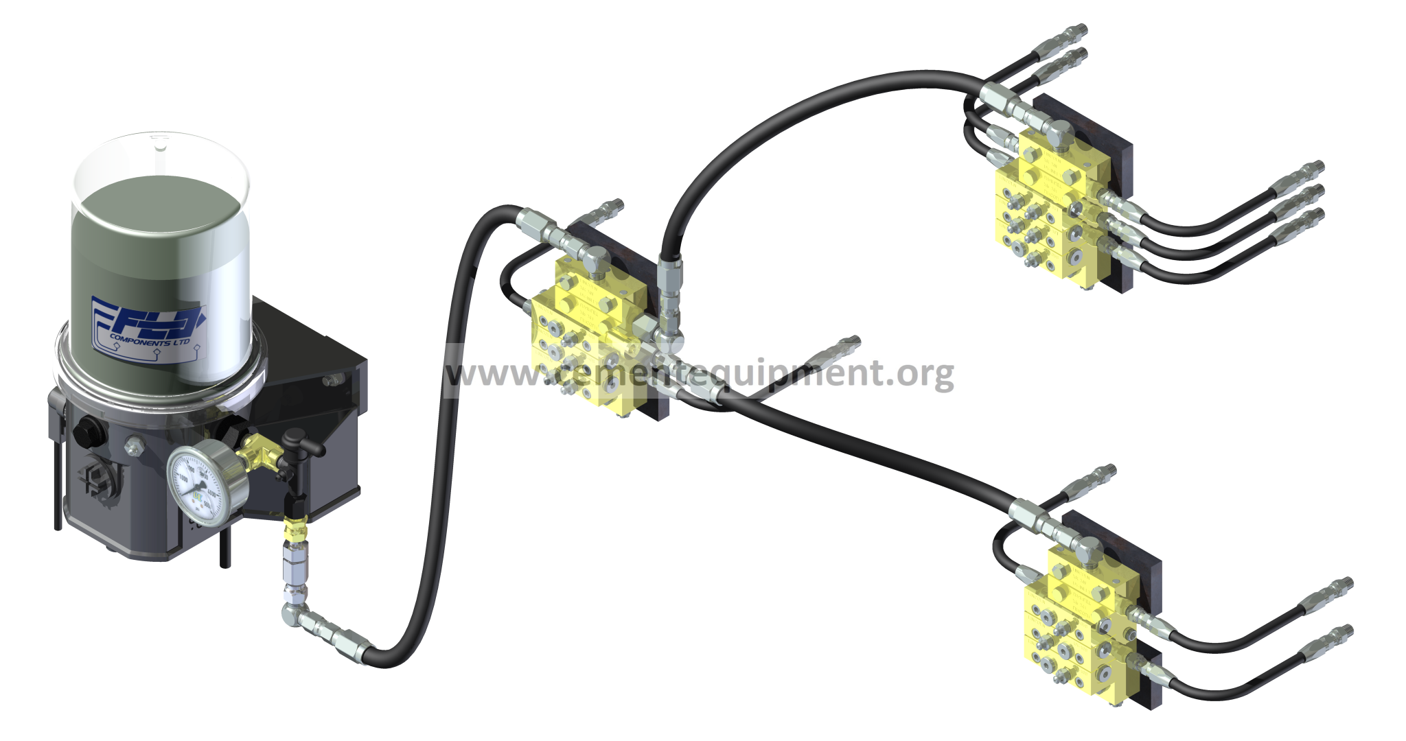
The fault behavior depends on the circuit design. In a progressive system, the metering pistons work in sequence; one blocked point or line can stop divider cycling and prevent downstream delivery. In a single-line injector system, injectors are arranged in parallel, so one blocked lubrication point may fail while other points continue to receive grease. Dual-line systems have their own changeover and metering logic.
This distinction matters before interpreting pressure. A high-pressure progressive system with a stopped cycle indicator points toward a downstream blockage. In a single-line system, normal main-line pressure with one dry bearing points more strongly toward that point’s injector, branch line or bearing fitting.
Pressure-path isolation checklist
- Confirm reservoir grease level and the exact approved lubricant.
- Run one controlled lubrication cycle and observe whether pump outlet pressure rises.
- If pressure does not rise, investigate pump prime, pump element, grease filter, air pocket and relief-valve path.
- If pressure rises excessively, investigate a blocked main line, divider/injector or lubrication point.
- Observe divider-cycle indicators or piston detector signals where fitted.
- Inspect branch tubing for leakage, crushing, disconnection or hardened grease.
- Work progressively toward the affected point rather than opening several lines at once.
- At the final point, prove the bearing fitting/path accepts lubricant before declaring the divider or pump repaired.
Go/no-go rule: do not increase pump pressure or bypass a pressure alarm just to force grease through a blockage. Locate the restricted component and restore the designed distribution path.
Seven-step workflow
- Verify grease level and confirm the correct grease grade/consistency is in the reservoir.
- Check pump outlet pressure during a lubrication cycle and compare with the system/OEM range.
- Inspect the main-line relief and pressure switch; low pressure can indicate leakage while excessive pressure suggests blockage.
- Observe progressive divider/injector indicators where fitted. A stopped divider can localize the blocked branch.
- Inspect lines and fittings for rupture, leakage, crushed tubing or loose connections.
- Under proper isolation, check the final fitting/path into the bearing for hardened grease or contamination.
- After repair, prove lubricant delivery at the affected point and trend bearing temperature/vibration over subsequent cycles.
Diagnostic decision matrix
| Evidence | Likely direction | Next check |
|---|---|---|
| Low pump pressure with grease leakage | Broken/open line | Main and branch lines |
| High pump pressure and no delivery | Blockage | Divider/injector/point fitting |
| Only one point dry while other points appear normal | Branch leakage or misrouting, a separate injector circuit, or an unverified progressive-cycle indication | Identify the actual metering architecture and outlet map; verify delivered grease at the point before assigning a local injector or fitting fault |
| Many points fail after grease change | Wrong/incompatible grease | Grease specification and purge plan |
| Pump runs but no outlet pressure | Pump prime/internal issue | Pump and reservoir feed |
Use the failure pattern to localize the blockage
No pressure anywhere: stay at the pump/reservoir/filter/prime/relief path. High pressure and no points receive grease: inspect the main line or first metering device. One progressive divider stops cycling: isolate its outlet circuits and the downstream point that is blocking sequence. Only one point is dry while others lubricate normally: first confirm whether the affected point belongs to an independent injector branch, a separate pump-fed circuit, or the same progressive divider sequence. A true blockage in a shared progressive sequence can stop that circuit, so check the circuit map, indicator evidence, line integrity and final fitting before assuming an isolated injector fault. Many points fail after a grease change: verify grease consistency, compatibility, temperature suitability and whether old hardened material is restricting the circuit.
A bearing point itself can be the restriction. If grease reaches the final hose but cannot enter the fitting or bearing path, replacing the pump will not solve the problem. Conversely, a disconnected branch can leave the pump apparently healthy while lubricant is discharged elsewhere instead of reaching the intended point.
Acceptance criteria
Verify the repaired lubrication circuit over repeated automatic cycles:
- Confirm the correct lubricant is in the reservoir and the pump primes normally.
- Record pump outlet pressure and pressure-switch/relief behavior through a complete cycle.
- Confirm divider, injector or metering indicators operate as designed.
- Physically prove lubricant reaches the previously dry bearing point using the OEM/plant verification method.
- Inspect the complete repaired line for leakage, crushing or loose connections.
- Trend the bearing temperature/vibration over subsequent operating cycles and confirm the dry-running symptom does not recur.
Use the lubrication-system OEM for pressure limits, grease consistency, metering quantity and cycle settings; do not use a universal pressure or grease-delivery value across different systems.
Common mistakes and repeat-failure traps
- Trusting pump-motor RUN status: it proves only that the drive runs, not that lubricant leaves the pump or reaches every point.
- Increasing pressure to clear a blockage: this can damage lines/components and defeat protection.
- Opening many lines at once: isolate the circuit systematically so the blockage location is not lost.
- Ignoring system type: a blocked progressive point can stop a sequence, while a single-line injector circuit may leave other points operating.
- Blaming the divider when the bearing fitting is blocked: prove delivery step-by-step to the final point.
- Ignoring grease compatibility and temperature: hardened or unsuitable grease can create widespread restriction after a product change.
Related Infinity guides
Build a stronger cement maintenance library
The Infinity for Cement Organization technical package contains 900+ technical files. It is a one-time $249.99 purchase, with instant download immediately after payment and lifetime updates forever at no additional cost.