Clinker Coolers: Complete Technical Guide
Clinker coolers are the quiet workhorses of the cement pyroprocessing line: the machines that receive the red-hot clinker at 1350 to 1450 degrees Celsius and return it to the plant in a state the rest of the process can handle: cooled, quenched, transportable and storage-stable: the cooler does not only protect the downstream equipment, it is the first and most profitable energy recovery unit of the entire kiln system, because a well-designed cooler hands back hundreds of kilowatt-hours of heat per ton of clinker in the form of secondary and tertiary air.
The Complete Cement Technical Package (931 files including the books, the courses, the Excel tools and the presentations: $249.99 one-time: instant download via the PayPal payment) includes this cooler guide together with the related files on kiln operation, heat balances, fans and refractories: the article walks the file: the role of the cooler, the three classic machine types, the modern alternatives, the air and heat balance, the quality effects of rapid cooling and the performance numbers of a well-run unit: the reader leaves with enough to specify, operate or audit a clinker cooler.
This page is organized as a working document: the thermal logic of the cooler comes first, the machine typology second, the operating and quality aspects third, and the performance and selection tools last: the file itself follows the same order, and the two tables of this article summarize the machine comparison and the key performance indicators that plant engineers quote at every audit.
1. The Role of the Cooler in the Pyroprocessing System
The kiln discharges clinker at a temperature of 1350 to 1450°C, still glowing and still losing heat at a rate that would ruin the handling equipment downstream: the cooler receives this material and performs four essential duties in one machine: it cools the clinker, it recovers heat, it quenches the mineralogy and it transports the material to the clinker storage.
- Cooling duty: the clinker must leave the cooler at a temperature above ambient by only 60 to 100 degrees, typically 80 to 130°C in a healthy grate cooler, so that the conveyors, the storage silos and the grinding plant can accept it;
- Heat recovery: the cooling air is the combustion air of the kiln and the precalciner: secondary air enters the kiln at 800 to 1100°C and tertiary air enters the calciner at 700 to 950°C in a modern system: the recovered heat is the largest free energy input of the plant;
- Mineralogical quenching: the rapid cooling below about 1250°C arrests the decomposition of the alite phase and fixes the glass content of the clinker: a properly quenched clinker is stronger and more reactive in the mill;
- Transport: the cooled clinker is discharged to the chain conveyor or the clinker silo at a measured rate that matches the kiln production: the cooler is also a buffer that absorbs the short-term throughput variations of the kiln;
The thermal weight of the task is easy to underestimate: the enthalpy of the clinker leaving the burning zone represents about 1200 to 1500 kJ per kg of clinker at reference temperatures: a grate cooler recovers 60 to 70% of that heat, the rotary cooler 50 to 60%, and the rest is lost with the exhaust air and the radiation: the difference of just a few percentage points of recovery is worth millions of dollars over the life of a 5000 tpd plant.
The cooler is also the newest part of the kiln system in engineering terms: the burning zone, the preheater and the mills were all mature by the 1920s, while the modern reciprocating grate cooler only arrived in the 1930s and the fixed-grate family in the 1990s: the development history explains the state of the equipment park of the world: many plants still operate coolers whose plates, fans and control logic belong to the 1970s, and every modernization study of such a plant begins and ends with the cooler, because the recovery losses of an old machine are the cheapest energy to recover in the entire plant: the file carries both the history and the retrofit logic, so the engineer can argue the priority list of his plant with numbers instead of opinions.
2. The Thermal Duty: Heat Recovery and Temperature Targets
Every cooler is, in the first place, a counter-current heat exchanger that uses ambient air as the working fluid: the air enters cold, passes through the clinker bed, and leaves hot: the same air then travels to the kiln burner or the precalciner, where its sensible heat replaces fuel that would otherwise be burned.
The heat balance of the clinker end of the kiln system is conventionally written around the cooler in these terms:
- Heat in with clinker: the clinker leaves the kiln at 1350-1450°C with an enthalpy of about 1250-1500 kJ/kg;
- Heat out with secondary air: the air to the kiln is heated to 800-1100°C and recovers roughly 350-500 kJ/kg of clinker;
- Heat out with tertiary air: the air to the calciner recovers another 350-450 kJ/kg in the modern precalciner lines;
- Heat out with cooler exhaust: the excess air leaves the cooler at 200-350°C, carrying the main unavoidable loss;
- Heat out with radiation and convection: the skin losses of the cooler housing, typically 20-60 kJ/kg depending on the insulation and the size;
The target figures of a modern cooler are well established in the industry: clinker discharge temperature 60-100°C above ambient, secondary air temperature above 900°C in the burning zone operation, cooler efficiency of 65-75% and a specific cooling air flow of 1.8 to 2.5 kg air per kg of clinker including the de-dusting: these are the numbers against which every optimization study is measured.
What happens when the cooling duty is not met is worth spelling out, because the consequences cascade through the whole plant: hot clinker above 150°C overloads the chain conveyors and the clinker silo, accelerates the wear of every downstream component and raises the temperature of the cement in the finish mill, which forces the mill operators to reduce the throughput or inject water: a cooler that discharges at 200°C instead of 100°C costs the plant in conveyor repairs, mill capacity and cement quality all at once: the thermal duty of the cooler, therefore, is not a comfort requirement but a production constraint, and the file ranks the consequences so that the plant can justify the cooler improvements to the management in the language of money.
3. The Grate Cooler: The Workhorse of the Modern Plant
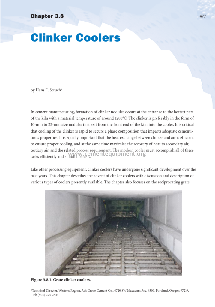
The reciprocating grate cooler is the dominant machine of the industry since the 1950s and it equips the overwhelming majority of the modern plants: the clinker falls from the kiln onto a perforated grate that moves the material forward in a shallow bed while cooling air is blown upwards through the grate from below.
- The grate surface: the modern coolers use rows of overlapping grate plates, reciprocating or forward-moving, with widths matching the kiln diameter and lengths giving the required retention time;
- The air supply: under-grate compartments divide the grate into zones, each fed by its own fan: the first zones receive the high-pressure air because the fresh hot clinker is fine and offers high resistance, the later zones run at lower pressure;
- The bed management: the bed height is typically 600 to 900 mm, and the grate speed adjusts automatically to keep the bed height constant as the kiln load varies;
- The recuperation zone: the first 40 to 50% of the grate length is the recovery heart: the air that passes through the hottest clinker becomes the secondary and tertiary air of the process;
- The cooling zone: the remaining length completes the cooling down to the 80-130°C discharge target, using a higher specific air flow that is vented through the dust filters;
The grate cooler achieves a cooling rate of 20 to 60 degrees per minute in the critical range and a heat recovery of 65-75%: it is also the most flexible machine, able to follow the kiln loads from 50% to 110% of design: the price of this performance is the mechanical complexity: many moving parts, grate plate wear, and a continuous maintenance demand that the plant must budget honestly.
Inside the machine, the construction details decide the operating results: the modern coolers are built as a series of air beams, each beam being a cast steel box that carries the grate plates and receives its air through the fixed end connections, while the hydraulic drive reciprocates alternate rows of beams so that the clinker walks forward on a waveform motion: the air distribution enters the bed as a series of jets through the holes of the plates, and the jet velocity at the recuperation zone is a design point of its own: too slow, the fine hot clinker sinters the bed; too fast, the fines are blown into the hood and the dust load of the kiln rises: the file documents the air beam geometry, the plate hole patterns and the pressure drops that distinguish a good grate design from a bad one, with the drawings and the numbers that the maintenance and the revamp engineers need.
4. The Rotary Cooler: The Classic Solution
The rotary cooler is a short inclined cylinder, refractory-lined at the feed end, that rotates slowly on two to three support stations while the clinker tumbles through it: the cooling air is drawn through the drum counter-currently by the kiln induced draft.
- The construction: a steel shell of 2.2 to 4.0 meters in diameter and 20 to 40 meters in length, refractory lined for the first third and fitted with lifting flights in the rear section;
- The air path: the combustion air enters through the discharge hood and passes through the tumbling clinker: there is no separate fan system, the kiln draught does the work;
- The cooling performance: the retention time is 15 to 30 minutes and the discharge temperature is 200 to 300°C, higher than the grate cooler, which limits the heat recovery to about 50 to 60%;
- The advantages: simplicity, low power consumption, no grate plates and no sealing problems: the machine is legendary for its low maintenance;
- The limitations: the coarse clinker cools unevenly, the fine fraction cannot be cooled in such a machine, and the kiln operation is coupled to the cooler air flow, which reduces the process flexibility;
The rotary cooler survives today mainly in the small and medium wet-process plants and in a few white cement installations where its gentle tumbling action protects the clinker: for the modern dry-process lines above 2000 tpd, the grate cooler is the standard, and the rotary cooler is confined to the capacity range where its simplicity outweighs its lower recovery.
The operating character of the rotary cooler deserves its own paragraph because it differs fundamentally from the grate machine: the clinker tumbling in the drum segregates naturally, the coarse nodules roll to the shell while the fines stay in the core, and the air takes the path of least resistance through the loose material: the result is a bed that cools unevenly, with the coarse fraction leaving hotter than the fines: the operators compensate with the drum speed and the damper, but the physics of the machine sets the ceiling of its performance: the file quantifies this segregation behavior and explains why the rotary machine, for all its simplicity, never reached the recovery of the grate designs, and it gives the practical guidance for the plants that still operate one: the optimal filling degree, the flight design in the cooling section and the handling of the clinker falls during the kiln start-ups.
5. The Planetary Cooler: The Kiln-Mounted System
The planetary cooler dispenses with a separate machine altogether: a ring of 7 to 11 tubes, each 1.0 to 1.5 meters in diameter, is attached to the kiln shell around the discharge section and rotates with the kiln: the clinker enters the tubes from the kiln nose and slides down them while air is aspirated through by the kiln draught.
- The layout: the tubes are welded to the kiln shell at staggered angles so that the tumbling motion of the kiln transports the clinker and exposes it to the air stream continuously;
- The air flow: all the cooling air is the kiln combustion air, there is no exhaust air stream and no cooler fan: the system is elegant but the fine clinker and the dust return directly to the kiln;
- The performance: the clinker discharge temperature reaches 200-300°C and the heat recovery is in the range of 50-60%, comparable to the rotary cooler;
- The merits: no separate drive, no grate, no fans, very low power: the ideal for the small plants on confined sites;
- The constraints: the kiln shell sees additional mechanical loading, the kiln alignment must tolerate the cantilever weight, and the cooling control is coupled to the kiln draft;
The planetary cooler was common on European small kilns in the 1960s and 1970s, it survives on many old lines, but it has disappeared from the modern vendor catalogs above 2500 tpd: the plant engineers who still operate one value its simplicity while counting the lost kilowatt-hours of the poorer recovery.
The planetary cooler also taught the industry two lessons that survive in the modern textbooks: first, the famous dust problem, the recirculation of the fine clinker and the dust with the air directly into the kiln, which raises the dust load of the kiln gases and disturbs the burning zone: second, the mechanical lesson of the shell loading, because the tubes hang on the kiln shell and the alignment of the kiln must absorb the unsymmetrical weight distribution: the modern designs of the 1970s solved the dust problem partially with the tangential inlet flaps and the separation chambers, but the fundamentals never changed: the file devotes its chapter to these two lessons, because they explain why the machine vanished from the large lines and they prepare the engineer who meets one in the field, often in the developing world where the old European plants were exported and still run.
6. The Modern Principles: Cross-Bar and Shaft Coolers
Two modern families complete the cooler typology of the file: the cross-bar grate coolers, which replaced the reciprocating plates with a stationary grate and moving bars, and the shaft or jetting coolers, which use pressurized shafts to fluidize and cool the clinker.
- The cross-bar cooler: the grate is fixed and the clinker is pushed forward by reciprocating cross bars: fewer moving parts, no grate plates to wear, very low air leakage, and a flatter bed profile;
- The static grate with air blast: several vendors market static coolers where the clinker slides over a stationary perforated floor and high-pressure nozzles below create air cushions that both transport and cool the bed;
- The efficiency gains: the modern systems reach cooling air flows of 1.6 to 2.0 kg/kg with a heat recovery of 72 to 78%, slightly above the classical reciprocating machines;
- The maintenance story: the wear parts move from the grate surface to the bars and the nozzles: the inspection intervals stretch with the better materials but the repairs are fewer and more precise;
- The retrofit path: the older reciprocating coolers are commonly converted to the fixed-grate principles in the revamp projects, with the recuperation zone changed first and the tail section second;
The vendor names differ but the engineering message is the same: the industry is moving towards the static bed and the air cushion because they solve the two oldest cooler problems, the grate leakage and the plate wear: the package file documents the principles without partisan bias, so the engineer can evaluate the alternative upgrades with his own numbers.
It is worth comparing the modern machines in the field before deciding, and the file provides the comparison framework: the cross-bar machines show their strength in the large plants above 5000 tpd where the availability of the coolers decides the annual production, while the jetting and static coolers have found their home in the smaller and medium plants and in the retrofit of the first compartments: the measured plants report recovery gains of 3 to 8 percentage points after the conversion, with the secondary air temperature climbing by 50 to 150°C and the fan power often falling because the even air distribution allows the lower pressure heads: the payback of such conversions is typically 2 to 4 years at the current energy prices, and the file presents three real case studies with the before-and-after balances so that the reader can recognize his own plant in one of them.
7. The Cooler Fans and the Air Distribution: The Combustion Balance
The cooler is a fan park as much as a heat exchanger: a 5000 tpd line typically installs 10 to 14 under-grate fans with a total installed capacity of 3000 to 5000 kW, and the way this air is distributed decides both the cooling result and the combustion air temperature.
- The zone pressures: the first compartments work at 500 to 800 mbar gauge with bed resistances of 300 to 500 mbar, the middle zones at 200 to 400 mbar and the last zones at only 50 to 150 mbar;
- The closed-loop control: the first-zone air is fixed first, then the secondary air temperature is trimmed by the grate speed and the bed height in the recuperation zone;
- The tertiary air take-off: the tertiary duct draws from the middle of the recuperation zone, where the clinker has passed the initial quench but still carries several hundred degrees of temperature;
- The false air discipline: the sealing between the fixed housing and the moving grate is the eternal battle: worn seals add false air that dilutes the secondary air temperature and destroys the recovery;
- The airflow measurement: every compartment measures its flow and pressure individually: the control room picture of the cooler is a diagonal matrix of fans, pressures and temperatures that the operator reads like a dashboard;
The air balance of the cooler is also the combustion balance of the kiln: a rule of thumb of the industry says that the secondary air temperature rises about 10°C for every percentage point of recovery gained, and the flame performance changes visibly: the burner engineer and the cooler operator must therefore speak the same language: the file dedicates a full chapter to this loop, with the control settings and the airflow tables of a typical 5000 tpd cooler.
In the control room, the cooler is operated on a cascade of setpoints that the file explains step by step: the first compartment air is held on the fixed flow to guarantee the quench, the bed height is held on the drive load, the grate speed follows the kiln feed rate, and the recuperation fan flows are trimmed against the secondary and tertiary air temperatures: the modern systems add the automatic bed-pressure control, where the pressure drop across the bed is measured and the grate speed adjusts in seconds to the lumps and the holes of the bed: the experienced operator learns to read the bed through the compartment pressure matrix, because a cold spot in the middle of the recuperation zone announces a hole that will dilute the secondary air temperature within minutes: the file includes the control block diagrams and the operator checklists that convert these principles into the daily routine of the shift.
8. The Cooling Rate and the Clinker Quality: Glass and Reactivity
Rapid cooling is not a luxury of operation, it is a quality instrument: the clinker phases react when they are red hot, and the cooler is the place where the mineralogy of the product is finally fixed.
- Alite protection: below 1250°C the alite phase begins to decompose into belite and free lime: fast cooling through the 1250-900°C window preserves the alite that the burning zone has created;
- The glass phase: the rapid cooling freezes part of the interstitial melt into glass, which raises the early strength of the cement; slow cooling crystallizes it into inert phases;
- The granulation: the hot clinker must pass through its plastic range quickly, otherwise the lumps sinter into the hard chunks that ruin the grinding and the silo flow;
- The reducibility: the oxidizing atmosphere of the cooler keeps the iron in the ferrite phases and prevents the formation of the reducing slag that discolors the grey cement;
- The white cement exception: the white clinker is quenched in water to fix the white crystal structure, a completely different regime that the file discusses separately;
The practical numbers are known: the optimum is a cooling rate of 20 to 60 degrees per minute through the critical window, and the standard grindability tests show that a well-quenched clinker grinds 5 to 15% easier than a slowly cooled one: the cooler, in other words, pays for itself three times: in energy, in equipment protection and in the final product quality: the package file quantifies all three with the tables of the measured plants.
The operator reads the cooling quality with the oldest instrument of the plant, the eye: the well-quenched clinker leaves the cooler with the characteristic blue-black shine and the sharp ringing sound when it falls, while the slowly cooled clinker appears dull, brownish and crumbly: the modern plants add the laboratory confirmation, because the free lime of the quenched clinker and the grindability test close the loop: the quarterly samples of the clinker from the well-cooled plants show the alite contents of 55 to 70% with the good polishing microscopy, while the poorly cooled batches show the typical decomposition rims around the alite crystals: the file includes the microscope photos and the grindability curves that let the quality laboratory recognize the signature of the bad cooling, and it ties the observations back to the operating parameters of the cooler so the quality problem can be traced to its mechanical cause in the machine.
9. The Heat Recovery to the Kiln and the Tertiary Air System
The recovered heat travels two roads: the secondary air enters the kiln hood and feeds the main flame, the tertiary air travels through a separate duct to the precalciner: the balance between the two streams is one of the main tuning levers of the modern plant.
- The secondary air: at 800-1100°C it carries 15-25% of the combustion air demand of the kiln flame and its temperature sets the flame ignition and the stability of the burning zone;
- The tertiary air: at 700-950°C it provides 40-60% of the total combustion air, the largest share, because the calciner burns the lion’s share of the fuel in the precalciner lines;
- The tertiary duct: it runs from the cooler hood over the kiln to the calciner, insulated and often equipped with a damper that splits the air between the kiln and the precalciner;
- The kiln stoppage case: when the kiln stops, the tertiary dampers close and the cooler must be cooled with the surplus air only: the control sequences of the file cover the emergency cases;
- The measurement: the temperatures are measured at the hoods and in the duct, and the plant balances the air flows against the fuel split to hold the target oxygen profile;
The recovery loop is the single largest free energy item of the cement plant: a modern cooler returns 50-60% of the clinker enthalpy, equivalent to roughly 30 to 50 kg of coal per ton of clinker saved compared to an inefficient cooler: the numbers justify every renovation, and the file includes the full worked heat balance of a 5000 tpd plant with the Excel tool to recompute the plant’s own case.
The recovery trade-off has one subtle corner that the file explains with care: the secondary and the tertiary air are free in the sense of fuel, but they are not free in the sense of electricity, because the fans that push the air through the bed consume 8 to 14 kWh per ton of clinker: the optimum of the plant is the point where the marginal fan kilowatt-hour is exactly worth the fuel it replaces, and the modern plants tune this point with the specific air flow: the tertiary air damper is the instrument of the day, because the split between the kiln and the calciner decides which combustion zone receives the hot air: too much to the kiln, the flame temperature rises and the NOx emissions climb; too much to the calciner, the kiln flame starves and the fuel split must move: the file presents the optimization curves of the two temperatures against the damper position, the practical tool that the plant engineers use in their monthly tuning sessions.
10. The Maintenance, the Refractories and the Wear of the Cooler
The cooler is the most maintenance-intensive machine of the pyroprocessing line, and the file gives the honest maintenance picture: the weekly greasing rounds, the quarterly grate inspections and the annual overhaul planning are the discipline that keeps the recovery percentages alive.
- The grate plates: the cast steel plates wear by abrasion and thermal shock: the service life is 12-24 months in the recuperation zone and 18-36 months in the tail, depending on the materials;
- The refractories: the walls above the recuperation zone are lined with dense and insulating bricks, the clinker inlet areas with castables: the inspection after every kiln stoppage is mandatory because the falling clinker erodes the linings quickly;
- The hydraulic drives: the grate reciprocation runs on hydraulic cylinders, and the oil cleanliness and the stroke adjustment are the classic failure points;
- The fans and dampers: the abrasiveness of the dust-laden air wears the impellers: the rotor balancing and the damper linkage checks belong to the monthly routine;
- The seals: the side seals and the suspension seal of the hood are the guardians of the false air: an audit of a plant often starts with the smoke test of the cooler casing;
The maintenance cost of a 5000 tpd grate cooler is typically 1.5 to 2.5 million US dollars per year including the refractories, the plates, the fans and the labor, against the 5 to 10 million dollars of the energy it handles: the ratios change when the discipline slips, and the file documents the failure patterns and the inspection checklists so the plant keeps the machine on the right side of the equation.
The human side of the cooler maintenance deserves its own lines, because the cooler is one of the most dangerous machines of the plant: the hot clinker at the hood, the moving grate plates under the bed and the dust-laden air make the workplace unforgiving: the safe practices of the file include the lockout sequences of the hydraulic drives, the cooling period of the bed before any entry, the confined-space rules of the under-grate chambers and the personal protection against the dust and the heat: the file also covers the emergency cases: the kiln stoppages with the hot bed, the water-injection cooling of the over-heated sections and the restart sequences that avoid the thermal shock of the refractories: the plants that follow these chapters report the lower injury rates and the higher availability, because the disciplined maintenance is also the fast maintenance.
11. The Performance Indicators: The Numbers of a Good Cooler
Every cooler audit in the industry is judged against a short list of numbers, and the file tabulates the healthy ranges for the grate coolers of the modern plants:
| Indicator | Healthy range | Comments |
|---|---|---|
| Clinker discharge temperature | Ambient + 60 – 100 °C | 80 – 130 °C typical absolute |
| Secondary air temperature | 800 – 1100 °C | Measured at the kiln hood |
| Tertiary air temperature | 700 – 950 °C | Measured at the take-off duct |
| Cooler heat recovery | 65 – 75% | Of the clinker enthalpy |
| Specific cooling air | 1.8 – 2.5 kg/kg clinker | Including de-dusting air |
| Bed height | 600 – 900 mm | Kept constant by the grate speed |
| Cooler exhaust air temperature | 200 – 350 °C | Vented to the de-dusting filters |
| Cooler fan power | 8 – 14 kWh/t clinker | Total installed, modern plants 10-12 |
The second table of the file compares the machine families on the same footing, so the selection can be argued with numbers instead of preferences:
| Feature | Grate cooler | Rotary cooler | Planetary cooler |
|---|---|---|---|
| Typical capacity range | 1000 – 12000+ tpd | 200 – 2500 tpd | Up to about 2500 tpd |
| Clinker discharge temperature | 80 – 130 °C | 200 – 300 °C | 200 – 300 °C |
| Heat recovery | 65 – 75% | 50 – 60% | 50 – 60% |
| Specific power | 8 – 14 kWh/t | 2 – 4 kWh/t | 1 – 2 kWh/t |
| Cooling air control | Independent zones + fans | Coupled to kiln draft | Coupled to kiln draft |
| Moving parts and wear | High | Low | Very low |
| Maintenance demand | High | Low | Very low |
| Best fits | Modern dry-process lines | Small wet-process lines | Small lines, tight sites |
The tables condense the experience of the industry: the engineer reads the row of his plant’s size and decides whether the recovery premium of the grate machine justifies its maintenance appetite: the file behind the tables carries the full discussion, the selection curves and the worked-sizing example of each family.
The audit practice that the file teaches follows a fixed sequence that any plant can copy: first, the heat balance is closed with the measured temperatures and flows; second, the air distribution is checked compartment by compartment against the design; third, the false air is measured with the oxygen profiles along the cooler; and fourth, the mechanical state of the plates, the seals and the drives is documented against the wear standards: the output of the audit is a shortlist of losses ranked by their monetary value, and the file provides the audit forms and the calculation sheet: the plants that run this audit annually report the sustained recovery gains of 2 to 5 percentage points, simply because the losses become visible and accountable: the performance indicators of this section are the yardsticks of the audit, and the second table doubles as the scoring card of the machine.
12. The Selection and Sizing Criteria of a Cooler
The sizing of a cooler follows the same logic as the sizing of every pyroprocessing machine: start from the production target and work backwards through the specific loads and the retention requirements.
- The throughput basis: the cooler is rated on the kiln production at 100% load plus the design margin, typically 10-20% above the nominal clinker output;
- The specific grate load: the grate area is chosen for a specific load of 25 to 45 t/m²/day for the modern fixed-grate machines, and 30 to 55 t/m²/day for the reciprocating designs;
- The retention time: the bed travel time is 20 to 40 minutes in normal operation, checked against the cooling curve of the clinker;
- The fan capacity: the installed air is 1.8 to 2.5 kg/kg of clinker, with the pressure heads selected per zone from the bed resistance calculation;
- The integration: the hood geometry and the tertiary take-off must match the burner and calciner flows, otherwise the recovery is lost before it starts;
A worked example from the file: a 5000 tpd kiln at 208 t/h needs a grate area of about 5000 divided by 35, roughly 145 square meters of active grate, an air flow of 1.9 kg/kg corresponding to about 125 kg/s of total air, and a fan park of about 11 compartments: the exercise takes ten minutes with the Excel tool of the package and it protects the project from the classic mistake of the undersized cooler that follows the plant all its life.
The retrofit path deserves its own numbers because most cooler improvements of the world happen on existing machines: the staged conversion begins with the recuperation zone, where the first two compartments are rebuilt with the fixed-grate modules and the high-pressure air beams, while the tail keeps the old plates: the second stage converts the middle section and the tertiary take-off, and the third stage replaces the tail fans with the modern low-pressure units: the measured plants report after stage one alone a secondary air temperature gain of 50 to 100°C and a specific fan power reduction of 2 to 4 kWh/t, because the fixed modules distribute the air more evenly at a lower pressure: the file includes the three-stage retrofit plans with the cost and payback tables of the typical cases, the argument that convinces the board room when the cooler modernization is on the agenda.
13. The Frequently Asked Questions
Why is a clinker cooler called a heat exchanger before a machine?
Because its primary product is not the cooled clinker alone but the recovered combustion air: the secondary air at 800-1100°C and the tertiary air at 700-950°C replace fuel that would otherwise be burned: the cooler, therefore, is the first energy recovery unit of the line, and every degree of air temperature is money saved in the coal bill.
Which cooler gives the best heat recovery?
The modern fixed-grate and cross-bar coolers recover 65 to 78% of the clinker enthalpy and cool the clinker to ambient plus 60-100°C: the rotary and planetary machines recover only 50 to 60% but cost little to maintain: the choice is a balance between the energy price and the maintenance budget of the specific plant.
Does rapid cooling really improve the cement quality?
Yes: fast cooling through the 1250-900°C window protects the alite from decomposition into belite and free lime, fixes part of the melt as glass which raises the early strength, keeps the iron oxidized and improves the grindability of the clinker by 5 to 15%: the cooler is a quality machine, not only a handling machine.
What is the typical power consumption of a grate cooler?
The fan park and the drives of a modern grate cooler consume 8 to 14 kWh per ton of clinker, with the modern fixed-grate machines at the lower end of the range: this must be weighed against the 30 to 50 kg of coal per ton of clinker that the good recovery saves.
How often does a grate cooler need its plates replaced?
The grate plates of the recuperation zone last typically 12 to 24 months and the tail plates 18 to 36 months, depending on the materials and the clinker temperature: the modern wear-resistant alloys and the fixed-grate designs stretch these intervals, but the annual overhaul inspection remains the law of the cooler.
14. Conclusion
The clinker cooler is the machine that closes the thermal cycle of the pyroprocessing line: it takes the kiln’s product, protects the downstream equipment, fixes the quality of the cement and hands the plant back its most valuable free energy as combustion air: the engineers who master the cooler master one of the largest economic levers of the plant.
The Complete Cement Technical Package includes this cooler guide with the machine comparisons, the heat balance tables, the sizing example and the Excel cooling-air tool: the one-time price of $249.99: the instant download: the library of the cement engineer: the coolers of the package, the numbers of the plant: the knowledge, ready to audit the next cooler of your plant.
Get this Clinker Coolers file + the full 931-file package
$249.99 — one-time purchase, instant download, lifetime access
This file is part of the Complete Cement Technical Package (931 files) available from cementequipment.org. Respective rights holders; library copy for the licensed single user.