Introduction To Kiln Area And Brief: Complete Guide & Downlo
The kiln area is the thermal heart of a cement plant, the region in which the raw meal is transformed into clinker, and for the engineer who enters a cement plant for the first time, the kiln area is also the most impressive and the most complex part of the installation. This article is an introduction to the kiln area and a brief description of its main systems, written for newcomers to the industry, for engineers moving into the pyro-processing discipline, and for anyone who needs a structured overview of the equipment that fills the kiln building and the preheater tower. The kiln area comprises the preheater tower with its cyclones and ducts, the calciner, the rotary kiln itself with its drive, its supports and its refractory, the clinker cooler, the firing system, the gas handling and the dust collection, and the auxiliary systems of the air, the water, the lubrication and the instrumentation. The article describes each system in turn, explains how the pieces fit together into the thermal process, gives the typical values of the operating parameters, and outlines the main operational considerations of each area. The objective is to give the reader a mental map of the kiln area, so that the more detailed technical material of this package, the combustion, the refractory, the mechanical design and the process control, can be placed in the context of the physical plant.
The Kiln Area as a Whole
The kiln area of a modern dry-process plant is dominated by two structures: the preheater tower, a concrete or steel structure of 60 to 120 m height that houses the cyclones, the ducts and the calciner, and the kiln building, which houses the rotary kiln, its drive and its supports, the kiln hood at the discharge end and the cooler below it. The raw meal is fed at the top of the tower, the fuel is introduced at the calciner and the kiln burner, the clinker exits at the bottom of the cooler, and the gas flows in the opposite sense, from the kiln through the tower to the dust collection and the stack. The area is served by the central control room, from which the operators supervise the whole process through the DCS, and by the local platforms and the accessways, which bring the operators and the maintenance crews to the equipment. The kiln area is the highest, the hottest and the dustiest part of the plant, and its operation, its maintenance and its safety require the highest level of technical discipline.
The thermal process of the kiln area can be summarized in a few lines. The raw meal, at about 60–80°C, is fed to the top of the preheater, where it is heated stage by stage by the rising gas: the evaporation of the free moisture in the upper stages, the dehydration of the clay minerals at 400–600°C, the decarbonation of the magnesium carbonate at 500–700°C, and the calcination of the calcium carbonate at 700–900°C, which is completed in the calciner to a degree of 85–95%. The calcined meal enters the rotary kiln, where it is heated to 1400–1500°C in the burning zone, the clinker minerals form in the presence of the liquid phase, and the clinker exits at 1350–1450°C to the cooler, where it is cooled to 60–100°C above the ambient temperature. The gas leaves the kiln at 1000–1100°C, passes through the calciner and the preheater, exits the tower at 300–340°C and is cleaned in the bag filter or the ESP before the stack. The whole process is continuous, and its stability is the daily objective of the operators.
The main parameters of the kiln area, with their typical values, are summarized in the following table, which the reader can use as a quick reference throughout this article and the rest of the package:
| Parameter | Typical value | Comment |
|---|---|---|
| Kiln production rate | 2,000–12,000 tpd clinker | Set by the kiln size and the system design |
| Kiln diameter | 3.5–6.0 m | Shell diameter of the modern dry kilns |
| Kiln length | 50–80 m | Length/diameter ratio 10–16 |
| Kiln speed | 2.5–4.5 rpm | Variable, with the auxiliary drive for the maintenance |
| Burning zone temperature | 1400–1500°C | Material temperature, measured by the radiation pyrometers |
| Kiln exit gas temperature | 950–1100°C | Gas entering the calciner and the preheater |
| Preheater exit gas temperature | 300–340°C | 5-stage tower; the 6-stage gives about 270–300°C |
| Calciner temperature | 850–900°C | Calcination degree at the kiln feed 85–95% |
| Clinker temperature at the cooler exit | 60–100°C above ambient | Grate cooler with the cooling air recovery |
| Secondary air temperature | 800–1100°C | Air to the kiln from the cooler hot end |
| Tertiary air temperature | 750–950°C | Air to the calciner from the cooler |
| Specific heat consumption | 3000–3400 kJ/kg clinker | Dry process with the 5-stage preheater |
| Kiln exit O2 | 1.5–3.5% | Control of the excess air |
| Free lime of the clinker | 0.5–2.5% | Fast quality indicator of the burning |
The Preheater Tower
The preheater tower is the heat exchanger of the kiln system, and it is the structure that gives the modern dry process its thermal efficiency. The tower houses the cyclones, arranged in stages of one or two cyclones each, the connecting ducts, the meal feeding system and, in the lower part, the calciner. The raw meal is fed to the top stage by the bucket elevator or the pneumatic conveying, and it descends stage by stage, dispersed into the gas in the riser ducts, heated by the direct contact, and separated in the cyclones. The gas, which enters the bottom of the tower from the kiln and the calciner at 850–1100°C, rises through the stages and exits at 300–340°C, having transferred most of its heat to the meal. The cyclone stages are typically five in the modern plants, and the number is an economic optimization: each additional stage recovers more heat, at the cost of the height, the pressure drop and the fan power.
The cyclones themselves are the separation devices of the tower. The gas and the meal enter the cyclone tangentially, the vortex carries the meal to the wall, and the meal falls through the cone to the next stage, while the gas exits through the vortex finder at the top. The separation efficiency of a well-designed cyclone is 90–96% per stage, and the escaping dust is carried upward, to be caught by the next stage or the filter. The performance of the tower is characterized by its temperature profile, the gas and the meal temperatures at each stage, and by the pressure drops, which are the indicators of the flows and the incipient blockages. The operation of the tower is monitored from the control room through the stage temperatures and pressures, and the tower is also the site of the SNCR injection for the NOx control, and of the gas analysis at the outlet for the emission monitoring.
The operational issues of the preheater are the blockages and the build-ups, caused by the condensation of the volatile components and the mechanical bridging of the material. The blockages are detected by the rising pressure drop of a stage, the falling temperature and the rising tower pressure, and their response includes the air cannons, the reduction of the feed and the fuel, and, in the worst case, the shutdown and the cleaning. The prevention of the build-ups is the control of the volatile inputs, the operating temperatures and the design of the internals, and the inspection of the tower at the kiln stops is a routine part of the maintenance. The preheater is the most failure-prone part of the kiln area, and its reliable operation is one of the main objectives of the kiln area management, supported by the detailed technical material on the circulation phenomena in this package.
The Calciner
The calciner is the vessel in which the main part of the calcination reaction is completed, and it is located in the gas path between the kiln inlet and the bottom cyclone of the preheater. The meal from the bottom stage of the preheater is fed into the calciner, together with the fuel, the kiln gas at 1000–1100°C and the tertiary air from the cooler at 750–950°C. The fuel, which represents 55–65% of the total thermal input, burns in the calciner at 850–900°C, and the heat of the combustion drives the calcination of the meal, which is completed to 85–95% by the time the meal leaves the calciner with the gas into the bottom cyclone. The calciner is a large vessel, with the internal mixing promoted by the swirl inlets and the baffles, and its gas residence time is 2–4 seconds, which is the time available for both the combustion and the calcination.
The calciner is also the emission control instrument of the system. Its moderate temperature, far below the kiln flame temperature, means that the thermal NOx formation is negligible, and the modern calciners are designed with the staged combustion, in which a part of the fuel is burned in a reducing zone that destroys the NOx from the kiln gas before the final combustion. The calciner is also the natural home of the alternative fuels: its moderate temperature, its long residence time and its mixing can accommodate the coarse and the slow-burning wastes that the kiln burner cannot handle, and the plants with the high substitution rates fire most of their alternative fuels here. The operation of the calciner is the control of its exit temperature, typically 850–880°C, which is the control of the calcination degree and, through it, of the kiln thermal load.
The design variants of the calciner are distinguished by the position and the gas path. The in-line calciner (ILC) is placed in the main gas path, and the kiln gas passes through it with the tertiary air; the separate-line calciner (SLC) has its own gas path and its own cyclone, which allows the independent control of the calciner and different fuel splits. The choice between the designs is made in the engineering of the plant, and the operation of both is the same in its essentials: the calcination temperature, the fuel and the air are controlled to achieve the target calcination degree at the kiln feed. The calciner, despite its size and its importance, is a simpler machine than the kiln: it has no moving parts, and its issues are the blockages and the deposit formation, which are managed with the same instruments and the same discipline as the rest of the tower.
The Rotary Kiln
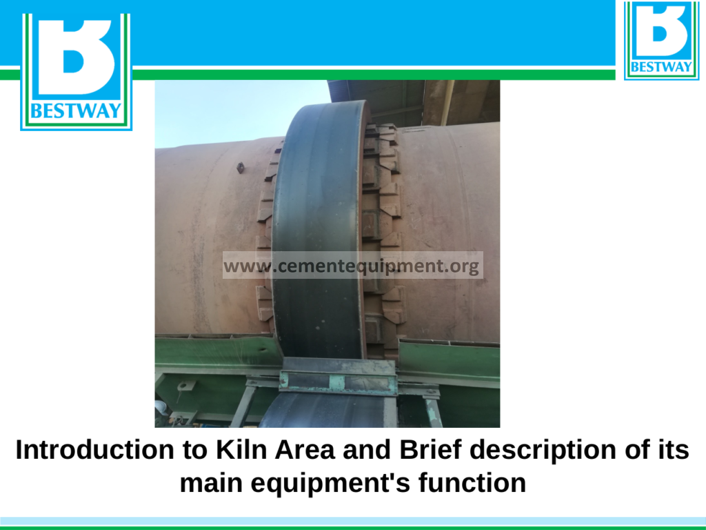
The rotary kiln is the iconic machine of the cement industry, a slowly rotating cylinder of 50 to 80 m length and 3.5 to 6 m diameter, mounted on the inclined supports and lined with the refractory. The kiln receives the calcined meal at its upper (feed) end and the clinker exits at the lower (discharge) end, and its rotation, at 2.5–4.5 rpm, carries the material slowly down the slope while the flame at the discharge end heats it to the clinkering temperature. The kiln shell is a welded steel cylinder of 40 to 120 mm thickness, supported on the riding rings (tyres) at the stations, and each station rests on the support rollers and the bearings, which carry the weight of the shell, the lining and the material. The kiln is rotated by the drive, the main gear and the pinion or the friction drive, at the kiln drive station, and the auxiliary drive rotates the kiln at a crawl speed during the maintenance and the emergency conditions.
The interior of the kiln is lined with the refractory bricks and the castables, and the lining is divided into zones that match the process: the inlet zone, where the meal enters and the calcination is completed; the transition zone, where the material is heated toward the clinkering temperature; the burning zone, the hottest part, where the clinker minerals form at 1400–1500°C; and the nose zone at the discharge end, where the clinker exits. The burning zone lining is the most demanding, exposed to the flame, the liquid clinker and the chemical attack, and it is made of the basic (magnesia-spinel) bricks that withstand the conditions; the other zones use the alumina and the silica-alumina bricks and the castables. The lining is protected by the coating, the layer of the clinker that adheres to the bricks in the burning zone, and the management of the coating, through the flame shape and the operation, is one of the central skills of the kiln operation.
The kiln is also a mechanical machine whose condition is monitored continuously. The kiln axis must be straight, and its alignment is measured and corrected by the adjustment of the support rollers; the ovality of the shell, its deviation from the circle under the rotating load, is measured at the supports and is the indicator of the shell and the lining condition; the shell temperature is scanned along the length and around the circumference, giving the continuous map of the lining condition and the coating; and the drive, the bearings and the rollers are monitored by the vibration and the temperature. The mechanical health of the kiln decides the refractory life and the availability, and the mechanical maintenance, the alignment, the roller adjustments and the shell repairs, is the discipline that keeps the kiln running between the relinings. The reader will find the detailed treatment of the kiln mechanics and the kiln maintenance in the dedicated articles of this package.
The Clinker Cooler
The clinker cooler is the machine that completes the thermal process of the kiln area. It receives the clinker at 1350–1450°C from the kiln and cools it to 60–100°C above the ambient temperature, and in doing so it performs three functions: it recovers the heat of the clinker in the secondary and the tertiary air, which preheats the combustion air of the kiln and the calciner; it fixes the quality of the clinker, because the cooling rate affects the phase composition and the grindability; and it conditions the clinker for the storage, the transport and the grinding. The modern cooler is the grate cooler, a moving grate on which the clinker is carried while the cooling air is blown upward through the bed: the air passes through the grate and the clinker bed, cooling the clinker and being heated itself, and the hot air is recovered at the cooler head, the secondary air to the kiln, and from the middle section, the tertiary air to the calciner.
The grate cooler is a machine with many moving parts, and its operation is the control of the clinker bed and the air flows. The bed must be even and stable: the clinker from the kiln falls onto the grate at the cooler head, where it forms a pile that is broken by the crusher, the clinker breaker, and spread across the grate by the distribution devices. The grate speed controls the bed depth, and the bed depth and the air flow control the cooling; the under-grate air is supplied by the fans, divided into the compartments, and the air distribution is managed so that the clinker is cooled evenly and the air is not wasted. The efficiency of the cooler is measured by the secondary and the tertiary air temperatures and by the cooler exhaust air, which carries the remaining heat to the dust collection; the recovery efficiency of a good cooler is above 70%, and its improvement is one of the main levers of the kiln system efficiency.
The operational issues of the cooler are the snowmen, the piles of the sticky clinker that build at the cooler head, the clinker pile-ups on the grate, the grate damage and the false air. The snowmen and the pile-ups are cleared by the air cannons and the manual intervention, and their prevention is the control of the kiln operation, the clinker chemistry and the cooler conditions; the grate damage is the consequence of the overheated operation and the foreign bodies, and its prevention is the protection and the monitoring. The cooler is also the source of the secondary air, and its operation is tightly coupled to the kiln and the calciner: a cooler problem, a snowman or a pile-up, immediately disturbs the secondary and the tertiary air, and through them the whole thermal process. The cooler is therefore operated and monitored with the same attention as the kiln itself, and its condition is inspected at every kiln stop.
The Firing System
The firing system of the kiln area comprises the kiln burner, the calciner firing, the fuel preparation and feeding, and the combustion air system. The kiln burner is the multichannel burner mounted at the kiln discharge end, through which the fuel and the primary air are injected into the kiln; the burner shapes the flame, and the flame shape decides the burning zone temperature, the coating, the NOx and the clinker quality, as described in the dedicated article of this package on the Fives Pillard burners. The calciner firing consists of the fuel lances and the nozzles in the calciner, fed by the separate fuel lines; the fuel split between the kiln and the calciner, typically 35–45% to the kiln and 55–65% to the calciner, is the central operating balance of the system. The combustion air is supplied by the primary air fans of the burner, the secondary air from the cooler and the tertiary air through its duct, and the draught of the system is maintained by the induced draft fan at the preheater exit.
The fuel preparation and the feeding systems are the upstream of the firing. The pulverized coal or the petcoke is ground in the fuel mill, transported pneumatically to the kiln and the calciner, and metered by the feeders; the alternative fuels are prepared, stored and fed through their dedicated systems. The quality of the fuel, its fineness, its moisture and its calorific value, decides the behavior of the flame, and the fuel management, from the procurement to the feeding, is part of the firing system discipline. The firing system is also the safety-critical area of the plant: the fuel lines, the burners and the flame supervision are protected by the interlocks and the procedures, and the operation of the firing system follows the strict rules of the burner management, as described in the safety section of this package.
The combustion control is the daily craft of the kiln operation. The operator manages the kiln fuel and the calciner fuel against the feed rate, the temperatures and the gas analysis, and the burner settings, the primary air ratio, the swirl and the axial air, are adjusted to shape the flame. The combustion is verified by the gas analysis at the kiln exit and the preheater exit, the oxygen, the CO and the NOx, and by the shell temperatures and the clinker quality. The firing system is the instrument by which the operator controls the kiln, and its mastery, which this package covers in the articles on the burners, the fuels and the combustion, is the core skill of the kiln operation.
Gas Handling and Dust Collection
The gas handling system of the kiln area moves the process gas from the kiln through the preheater to the stack, and it comprises the ducts, the fans, the dust collection and the auxiliary systems. The induced draft fan, located after the dust collection, provides the draught for the whole system, and its speed or its vanes control the gas flow and the pressures; the fan is one of the largest motors of the plant, and its operation is the control of the system pressure, the kiln exit and the preheater pressures, which are set against the process requirements. The gas is cleaned in the dust collection system, the bag filter or the electrostatic precipitator, which captures the dust before the gas reaches the stack; the collected dust is returned to the process, to the raw mill or the kiln feed, and the dust handling is part of the material balance of the plant.
The gas analysis is the instrumentation of the gas handling and the combustion. The analyzers at the kiln exit and the preheater exit measure the oxygen, the CO, the NOx and the SO2, and their data are used for the combustion control, the emission monitoring and the compliance reporting. The sampling systems of the analyzers are the maintenance-intensive part of the instrumentation, and their reliability is a condition of the process control and the environmental compliance. The continuous emission monitoring at the stack completes the gas instrumentation, and its data are reported to the authorities at the defined frequency, with the calibrations and the audits that the regulations require.
The auxiliary gas systems serve the process and the environment. The kiln gas bypass, where installed, diverts a part of the kiln gas around the preheater, removing the volatile components and protecting the tower from the build-ups; the bypass gas is cooled, dedusted and exhausted, and the bypass dust is handled separately. The false air, the air that enters the system through the leaks at the seals and the openings, is the enemy of the efficiency, because it dilutes the gas, lowers the temperatures and increases the fan load, and its control, through the sealing and the pressure management, is part of the operating discipline. The gas handling is the plumbing of the thermal process, and its reliable operation, without the leaks, the blockages and the fan problems, is the condition of the stable operation of the whole kiln area.
The Kiln Drive and the Mechanical Supports
The kiln drive is the assembly that rotates the kiln, comprising the motors, the gearboxes, the pinion and the main gear, or, in the modern kilns, the friction drive with the driven rollers. The main drive rotates the kiln at the operating speed, 2.5–4.5 rpm, through the speed control of the variable speed motors, and the auxiliary drive, a small diesel or electric motor with its own gearbox, rotates the kiln at a crawl speed of 0.1–0.5 rpm for the maintenance, the alignment checks and the emergency conditions. The drive station is typically located at the middle of the kiln, at the drive tyres, and the torque is transmitted through the main gear bolted to the shell. The drive is monitored by the vibration and the temperature, and its maintenance, the gear lubrication, the alignment and the bearing care, is planned with the kiln stops.
The kiln supports are the stations at which the shell is carried, each comprising the riding ring (tyre), the support rollers, the bearings and the base frame. The shell rests on the tyres, which are fitted around the shell at the support positions, and the tyres rotate with the shell while the rollers, mounted on the base frame, carry the weight and guide the rotation. The axial position of the kiln is controlled by the thrust rollers, which hold the kiln against the downhill slide, and the axial movement of the kiln, which floats up and down the tyres with the thermal expansion and the load changes, is one of the classic monitoring observations of the kiln mechanics. The alignment of the kiln, the straightness of the axis and the level of the supports, is measured periodically, and the adjustments of the support rollers correct the alignment and the load distribution.
The mechanical health of the kiln is the condition of its refractory life and its availability. The kiln shell is a structure that is never at rest: it rotates, it heats and cools, it flexes under the load, and the ovality, the deviation from the circular shape, is the indicator of the shell and the lining behavior. The ovality at the tyres, measured by the instruments or the sensors, is controlled within the limits that the lining can tolerate, and the shell temperature scanning shows the hot spots that indicate the lining wear. The alignment, the ovality and the shell temperatures are the three measurements of the kiln mechanical condition, and their monitoring and their management, which the package covers in the articles on the kiln mechanics, are the substance of the kiln mechanical maintenance.
The Auxiliary Systems of the Kiln Area
The auxiliary systems of the kiln area support the main process: the compressed air, the cooling water, the lubrication, the hydraulic systems, the electrical supply and the instrumentation. The compressed air serves the air cannons of the preheater and the cooler, the instrumentation, the cleaning and the maintenance tools, and its reliable supply is a condition of the operation: the failure of the compressed air disables the cleaning devices and the instruments. The cooling water serves the kiln bearings, the cooler bearings, the pumps and the sample coolers, and its quality and its availability are managed with the water treatment and the monitoring. The lubrication systems serve the kiln tyres and rollers, the drive and the bearings, with the oil and the grease that protect the sliding and the rolling surfaces; the lubrication of the kiln tyres, where the shell slides relative to the tyre, is a classic maintenance discipline of the kiln.
The instrumentation and the control complete the auxiliary picture. The kiln area is the most instrumented part of the plant: the temperatures, the pressures, the flows and the gas analyses are measured at the defined points, the DCS displays the process to the operators, and the advanced control systems support the operation. The instruments are maintained and calibrated on the defined schedules, because the process is controlled through them and the safety interlocks depend on them. The electrical supply of the kiln area, the motors, the switchgear and the cabling, is maintained for the availability, with the backup systems, the uninterruptible power for the control and the emergency lighting, because a power failure in the kiln area is a serious event that requires the emergency procedures, the auxiliary drive operation and the safe shutdown.
The safety systems of the kiln area are the final auxiliary system. The area is protected by the fire detection and the suppression, the gas detection where the fuel is handled, the confined space procedures for the vessels, the hot work permits for the repairs, and the fall protection at the heights. The kiln area is the highest-risk area of the plant, and its safety is managed through the risk assessments, the procedures and the training, as described in the safety material of this package. The reader who understands the kiln area as the assembly of the process, the machines and the auxiliaries that this article has described will be able to place every detail of the package in its physical context, and that understanding is the foundation of the mastery of the cement process.
Frequently Asked Questions about the Kiln Area
What are the main components of the kiln area?
The preheater tower with the cyclones, the calciner, the rotary kiln with its drive and supports, the clinker cooler, the firing system, the gas handling and the dust collection, and the auxiliary systems of the air, the water, the lubrication and the instrumentation.
What is the function of the preheater?
The preheater transfers the heat of the kiln gas to the raw meal in the cyclone stages, heating the meal from the ambient temperature to about 850°C and evaporating the moisture and dehydrating the clay minerals, so that the main calcination is completed in the calciner.
Why is the calciner used?
The calciner completes the calcination of the raw meal at a moderate temperature with its own fuel and air supply, which keeps the kiln thermal load low, allows the high production rates and keeps the NOx formation low, because the calcination is the largest heat demand of the process.
What happens in the burning zone of the kiln?
The material is heated to 1400–1500°C by the flame, the liquid phase forms, and the clinker minerals, the alite and the belite, crystallize from the melt. The clinker exits the kiln at 1350–1450°C to the cooler.
What is the function of the clinker cooler?
The cooler cools the clinker from 1400°C to 60–100°C above ambient, recovers the heat in the secondary and the tertiary air for the kiln and the calciner, and fixes the clinker quality through the cooling rate.
What are the main operational risks of the kiln area?
The preheater blockages, the kiln refractory failures, the mechanical problems of the shell and the drive, the cooler problems and the process instabilities. They are managed by the monitoring, the operating discipline and the maintenance, which this package covers in detail.
Summary and Final Recommendations
The kiln area is the thermal heart of the cement plant, and this article has given the reader a structured introduction to its main systems: the preheater, the calciner, the rotary kiln, the cooler, the firing system, the gas handling and the auxiliaries, with the typical values of the main parameters in the reference table. The recommendations for the reader who is new to the area are these: learn the gas flows and the material flows of the system, because the process is the movement of the heat and the material through the tower and the kiln; learn the instrument readings of each section, because the control room is the map of the process; walk the area with the experienced operators, because the physical plant teaches what the drawings cannot; and build the understanding systematically, from the overview of this article to the detailed material of the package, the combustion, the refractory, the mechanics and the control. The kiln area rewards the engineers who master it with the deepest technical understanding and the highest responsibility of the plant, and this package has been assembled to support that mastery, article by article, from the introduction of this page to the most advanced technical material of the library.
Get this cement file + the full 931-file package
$249 — one-time purchase, instant download, lifetime access
This file is part of the Complete Cement Technical Package (931 files) available from cementequipment.org. Respective rights holders; library copy for the licensed single user.