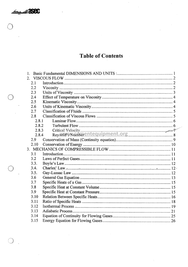
Basics Of Fluid Mechanics And Thermodynamics: Complete Guide
The fluid mechanics and the thermodynamics are the two mother sciences of the cement process: the fluid mechanics governs the movement of the gases through the kiln, the preheater, the mills and the filters, and the thermodynamics governs the exchange of the energy between the fuel, the flame, the material and the gas: the fan that pulls the kiln, the cyclone that loses the pressure, the cooler that recovers the heat and the preheater that exchanges it are all the creatures of these two sciences: the engineer who masters the basics reads the plant as the continuous conversation of the flows.
The Complete Cement Technical Package (931 files including the books, the courses, the Excel tools and the presentations: $249.99 one-time: instant download via the PayPal payment) includes this fundamentals file with the equations, the worked examples, the unit tables and the calculation tools: the article follows the file: the gas properties, the pressure, the flow, the fans, the heat and the energy balance: each chapter with the numbers of the plant.
This guide is written for the engineer who meets the formulas again after years on the floor: the derivations are brief, the applications are concrete, and every variable is explained with the cement plant in mind: the duct of the raw mill, the fan of the kiln, the thermometer of the cyclone: the equations of the file appear on the whiteboard of every plant meeting, and the article makes them the common language of the shift and the office.
1. The Gases of the Cement Plant: The Composition and the Properties
The working fluid of the cement process is the gas: the combustion gases of the kiln, the drying gases of the mills and the air of the cooler: its properties drive every calculation of the file:
- The composition: the cement kiln gases: nitrogen 70 to 75 percent, carbon dioxide 15 to 25 percent, oxygen 1 to 4 percent, water vapor 2 to 10 percent, with the minor monoxide, the sulfur and the nitrogen oxides in the traces: the raw mill drying gas is the mixture of the kiln gases and the ambient leak air:
- The density: the ideal gas law: the density of the dry air at the standard conditions 1.225 kilograms per cubic meter at 15 degrees and 1 atmosphere, and it falls with the temperature: at 200 degrees the air density is 0.75, at 350 degrees 0.57 kilograms per cubic meter: the density-temperature table of the file is the friend of the instrument engineer:
- The humidity: the water vapor lowers the gas density and changes its heat capacity: the humid air at 10 percent water vapor is lighter by the factor of the molecular weights: the moisture of the gas is the drying capacity of the mill chapter, quantified later:
- The viscosity: the gas viscosity rises with the temperature: the air at 20 degrees 18.1 micro-Pascal-seconds, at 300 degrees 29.7: the viscosity enters the Reynolds number and the pressure loss equations: the effect of the temperature on the fan power passes through the density, and on the friction through the viscosity:
The gas table of the file gives the properties at the intervals of the plant temperatures: the engineer interpolates the density, the specific heat and the viscosity without the laboratory: the instruments of the plant measure the temperature and the pressure, and the tables convert them into the mass flows the process control counts: the % the mass balance: the gas properties are the alphabet of the plant’s breathing.
2. The Pressure: The Static, the Dynamic and the Total Head
The pressure is the language of the gas flow, and the plant measures it in the Pascals and the millimeters of the water column:
- The static pressure: the pressure of the gas at rest relative to the ambient: the kiln system operates in the slight negative pressure of 50 to 500 Pa below the atmosphere: the draft of the induced draft fan overcomes the resistance of the whole line: the static pressure is what the pressure transmitters of the plant measure:
- The dynamic pressure: the pressure of the moving gas, proportional to the square of the velocity: pd = 0.5 x density x v2: at 15 meters per second in the standard air the dynamic head is 138 Pa: the dynamic head is the preferred measurand of the pitot traverses:
- The total pressure: the sum of the static and the dynamic pressures: the fan catalogues characterise their machines by the total and the static pressures: the fan static pressure of the raw mill circuit 4,000 to 7,000 Pa, of the kiln induced draft fan 6,000 to 9,000 Pa:
- The units conversation: 1 millimeter of the water column = 9.81 Pa, 1 kilopascal = 101.97 millimeters of the water column, 1 bar = 100 kilopascals: the plant instruments display the kilopascals and the millimeters and the operator of the file converts without the hesitation:
The pressure profile along the kiln line tells the engineer the health of the system: the draft at the kiln inlet, the preheater cyclones and the filter each consume their share: the blocked cyclone tower shows the climbing pressure drop, the open bypass shows the falling: the file’s pressure profile sheet of a typical 5,000 tonnes per day line maps the losses: the kiln inlet -2,000 Pa, the top cyclone -4,500, the mill -6,500, the filter -7,500: the reading of the profile is the daily diagnosis of the flow path.
3. The Bernoulli Equation and Its Applications in the Plant
The Bernoulli equation is the energy statement of the ideal flowing gas, and its practical forms organize the plant calculations:
- The equation: for the steady flow along the streamline: the static plus the dynamic plus the elevation heads are constant, minus the friction losses: p1 + 0.5 rho v1^2 + rho g z1 = p2 + 0.5 rho v2^2 + rho g z2 + the losses: in the compressible flows of the plants the density corrections of the file handle the deviations:
- The application to the measurement: the pitot tube, the venturi and the orifice all read the flow from the dynamic head: the pitot static difference = 0.5 rho v2: the velocity from the pressure: the pitot traverse of the duct (the measuring points of the file, 10 to 20 points of the log-Tchebycheff method) gives the average velocity and the volumetric flow:
- The application to the draft: the kiln system: the gas accelerates at the burner pipe exit, the static pressure falls, and the draft at the kiln hood balances the flame momentum: the cold air of the hood leaks in when the dynamic pressure of the jet grows: the design of the kiln hood pressure at -20 to -50 Pa keeps the flame stable and the false air low:
- The application to the nozzle ring: the vertical mill nozzle ring: the gas accelerates through the annular gap, the dynamic pressure rises, and the material is lifted: the velocity selection of the 40 to 90 meters per second separates the fines from the coarse: the Bernoulli balance of the lift zone is the file’s worked example of the ring velocity:
The equation appears in the plant at every turn: the belt of the draft gauge, the pitot of the fan test and the nozzle of the mill follow the same physics: the file develops the equation once and then applies it in the six plant situations with the numbers: the engineer who masters the Bernoulli sees the plant as the network of the energy lines: the duct, the fan and the cyclone as the stations of the one balance.
4. The Flow Regimes and the Friction Losses: The Reynolds and the Darcy
The gas flow in the ducts of the plant is almost always turbulent, and its resistance follows the classical laws:
- The Reynolds number: Re = rho v D / mu: the ratio of the inertia to the viscosity: below 2,300 the flow is laminar, above 4,000 turbulent: the plant ducts run at the Reynolds numbers of 100,000 to 2,000,000, deeply turbulent:
- The Darcy friction: the pressure loss of the straight duct: dP = f x L/D x 0.5 rho v2: the friction factor f for the industrial ducts 0.012 to 0.025 by the Moody chart at the typical roughness 0.15 to 0.6 millimeters of the steel and the coated surfaces:
- The fitting losses: the bends, the branches, the transitions and the dampers add the loss coefficients: the 90-degree bend of the rounded elbows 0.2 to 0.5, the sharp bends 0.8 to 1.2, the sudden expansions 0.5 to 1.0 of the dynamic heads: the fitting losses of the compact plants approach the duct friction in the total:
- The duct sizing rule: the economic velocities: the low-pressure ducts 12 to 18 meters per second, the fan ducts 18 to 25, the dedusting headers 15 to 22: the too-high velocity multiplies the friction and the wear, the too-low enriches the dust settlement: the sizing tables of the file give the duct diameters for the flow and the temperature:
The friction losses are the direct opponent of the fan: every duct detail of the plant contributes its share, and the total resistance line (the system curve) meets the fan curve at the operating point: the pressure loss calculation of the file walks the raw mill circuit duct by duct: the sum of the components 5,500 Pa at the design flow: the fan selection then matches the machine to the curve: the duct designer and the fan buyer speak the one equation.
5. The Fans of the Plant: The Types and the Curves
The fans are the movers of the gas, and the plant employs the whole family of the machines:
- The centrifugal fans: the radial, the forward-curved and the backward-curved blades: the backward-curved with the higher efficiency (75 to 85 percent) and the self-limiting power characteristic, the standard of the large kiln fans: the radial blades for the dust-laden gases with the wear allowance:
- The axial fans: the propeller machines of the cooling towers, the clinker cooler and the heat exchanger air: the high flows at the low pressures, the efficiencies 70 to 85 percent with the adjustable blades:
- The classic fans of the cement line: the kiln induced draft fan at 5,000 to 9,000 Pa and the flows of millions of cubic meters per hour, the raw mill fan, the bag filter fans, the cooler fans of the 50 to 200 kilowatts each, the preheater booster fans: the file’s fan list of the typical 5,000 tonnes per day plant counts the machines and their duties:
- The performance curve: the characteristic of the fan: the pressure against the flow at the constant speed: the operating point is the intersection with the system curve: the fan runs stable at the point of the positive slope; the surge of the low flows is the danger zone of the compressor-like operation:
| Fan | Flow (m3/h) | Pressure (Pa) | Power (kW) |
|---|---|---|---|
| Kiln ID fan | 900,000 – 1,300,000 | 6,000 – 9,000 | 2,500 – 4,000 |
| Raw mill fan | 500,000 – 800,000 | 5,000 – 7,000 | 1,200 – 2,000 |
| Finish mill fan | 300,000 – 500,000 | 3,500 – 5,500 | 600 – 1,000 |
| Cooler fans (total) | 500,000 – 800,000 | 3,500 – 7,000 | 1,500 – 2,500 |
| Bag filter fan | 400,000 – 700,000 | 1,500 – 3,500 | 400 – 800 |
The fan table of the file is the power map of the gas circuits: the fans consume 15 to 25 percent of the electrical energy of the plant, and their operating points are the daily optimization targets: the fan curve of the installed machine, the system curve of the line and the measured operating point form the triangle of the tuning: the file teaches the field test of the fan (the pitot traverse and the motor power) that verifies the actual duty against the nameplate.
6. The Fan Laws and the Control of the Flow
The affinity laws of the fans govern every adjustment of the gas circuits:
- The fan laws: at the constant geometry: the flow is proportional to the speed, the pressure to the speed squared, the power to the speed cubed: the speed change of 10 percent changes the power by 33 percent: the most important numbers of the fan operation: the law of the cube explains the energy logic of the variable speed drive:
- The density effect: at the constant speed and the flow, the pressure and the power change with the gas density: the same fan at 300 degrees delivers the lower weight of the flow and consumes the proportionally lower power: the summer and the winter difference of the plant fans follows the ambient density:
- The damper control: the throttling of the inlet or the outlet dampers changes the system curve: the flow reduces at the roughly constant speed: the efficiency of the throttled operation falls and the specific power suffers: the damper is the oldest control and the least efficient:
- The variable speed control: the variable frequency drive softens the fan: the flow follows the speed, and the power follows the cube: the saving of the VSD versus the damper at the 80 percent flow is the factor of the two: the retrofits of the kiln fans with the drives pay back in the 1 to 3 years of the typical cases:
- The parallel operation: the parallel fans split the flow and their curves add at the equal pressure: the parallel instability of the two kiln fans demands the equal-speed operation and the common point of the control: the file documents the parallel curves and the failure mode of the one fan dropping the two:
The fan laws turn the operations into arithmetic: the plant reduces the raw mill gas flow by the 10 percent for the economy and reads the power of the fan at exactly the predicted 27 percent reduction: the file’s fan law calculator and the worked examples of the damper-versus-drive comparisons give the engineer the numbers of the annual energy savings: the control of the gas flow is the control of the first movable cost of the plant.
7. The First Law of the Thermodynamics: The Energy Balance of the Plant
The thermodynamics of the cement plant begins with the first law: the energy is conserved, and every process of the plant obeys the one balance:
- The statement: the energy of the system changes by the heat added and the work done: dU = Q – W: for the steady flow processes the enthalpy form governs: H2 – H1 = Q – W: the steady flow of the gases, the material and the air through the plant sections are the enthalpy balances:
- The enthalpy: the heat content per kilogram of the gas or the material: for the gas h = cp x T with the reference at 0 degrees: for the clinker the enthalpy includes the heat of the reactions: the file uses the enthalpy of the gas, the raw material and the clinker throughout the balances:
- The heat balance of the kiln: the fuel energy in equals: the clinker formation heat, the sensible heat of the clinker, the exit gas heat, the shell losses, the false air warming and the unaccounted losses: the balance of the typical kiln: 50 to 55 percent to the clinker formation, 20 to 30 percent to the exit gas and the cooler, 8 to 12 percent to the shell losses:
- The balance practice: the monthly heat balance of the plant quantifies the losses and targets the improvements: the exit gas heat reduction via the preheater efficiency, the shell losses via the refractory, the cooler losses via the recuperation: the file’s balance template computes the sections from the measured flows and temperatures:
The first law is the accountant of the energy: every ton of the fuel that cannot be found in the products is the loss the engineer must explain: the heat balance worksheet of the package performs the section balances automatically, and the plant reviews the monthly printout as the health report of the thermal system: the thermodynamics is the bookkeeping of the kiln, and the file is the ledger.
8. The Heat Transfer: The Conduction, the Convection and the Radiation
The heat moves through the plant by the three mechanisms, and their mix depends on the service:
- The conduction: the heat flow through the solids: the kiln shell, the refractory walls, the insulation: the Fourier law q = k x dT/dx: the thermal conductivity of the fireclay 1.0 to 1.5 W/mK with the castable and the brick: the conduction drives the selection of the refractory thickness for the shell temperatures below 280 degrees:
- The convection: the heat exchange between the gas and the solid surfaces: the cyclone wall, the cooler bed, the mill interior: the Newton law q = h x dT: the convective coefficients of the gas flows 10 to 100 W/m2K at the plant velocities: the convection is the dominant mechanism of the preheater and the cooler:
- The radiation: the heat exchange by the electromagnetic waves, proportional to the fourth power of the absolute temperature: at the kiln temperatures above 1,000 degrees the radiation dominates: the flame radiates to the kiln charge and the walls, and the regenerative radiation of the flame and the wall pair is the mechanism of the kiln’s heat delivery:
- The combined transfer of the kiln: the flame temperature 1,700 to 2,000 degrees (with the calcination the effective 1,500 to 1,800), the gas and the wall radiation to the charge, the charge bed rotating and mixing the heat: the heat transfer coefficients of the burning zone 200 to 400 W/m2K, falling along the kiln as the temperatures drop:
The heat transfer mechanisms explain the design of the plant: the preheater cyclones are the convective exchangers with the large gas-solid surface, the burning zone is the radiative chamber, and the shell insulation is the conduction barrier: the file explains each service zone with its dominant mechanism and the coefficients: the engineer who reads the transfer knows why the kiln burns with the radiation and cools with the convection.
9. The Heat Exchangers of the Cement Line: The Preheater, the Cooler and the Mill
The cement plant is a chain of heat exchangers, and the thermodynamics basics unlock each one:
- The preheater cyclone tower: the suspension preheater at 4 to 6 stages: the kiln exit gas heats and reacts the raw meal in the counter-current cascade: the efficiency of the stage is the outlet gas temperature minus the meal temperature, measured as the approach of 30 to 80 degrees: the exit gas of the 5-stage tower at 290 to 340 degrees versus the 6-stage at 260 to 300:
- The calciner: the combustion chamber in the tower where the meal decalcines at 850 to 900 degrees: the fuel split of the kiln and the calciner (35/65 to 45/55) spreads the firing and increases the cement production of the kiln: the calciner is the birth of the modern precalciner plants:
- The clinker cooler: the grate cooler recovers the heat of the clinker at 1,400 degrees: the air flows up through the clinker bed: the primary and the secondary air to the kiln, the tertiary air to the calciner, the excess to the waste and the dryers: the cooling air per kilogram of the clinker 1.8 to 2.5 kilograms: the cooler efficiency 65 to 75 percent:
- The mills as heat exchangers: the raw mill uses the kiln gas to evaporate the feed moisture: the drying capacity is the gas flow times the enthalpy drop across the permitted temperature window: the mill gas exchange closes the heat loop of the plant: the file’s drying calculation: the mass of the evaporated water per hour from the gas flow, the entry and the exit temperatures:
The exchanger chain of the plant is the one thermal conversation: the kiln gives its heat to the meal and the gas, the preheater to the meal, the cooler back to the combustion air, and the mills to the raw material and the cement: the thermodynamics of the file ties the sections together, and the plant engineers follow the heat from the flame to the stack and the clinker.
10. The Combustion and the Enthalpy of the Fuels
The fuels of the cement plant are the chemical energy of the process, and their combustion obeys the basic thermodynamics:
- The fuels: the coal, the petcoke, the gas, the fuel oil and the alternative fuels: the net calorific values: the coal 24 to 30 MJ/kg, the petcoke 30 to 35, the gas 45 to 48 MJ/kg: the file’s fuel property table normalizes the purchases to the equal energy basis:
- The combustion reaction: the carbon and the hydrogen combine with the oxygen: the stoichiometric air of the coal is about 7.5 to 8.5 kilograms of the air per kilogram of the fuel: the excess air of the kiln 10 to 25 percent, visible in the oxygen of the kiln gases 1.5 to 3.5 percent:
- The flame temperature: the theoretical adiabatic flame temperature of the coal combustion with the preheated air reaches 2,000 to 2,200 degrees: the actual flame of the kiln at 1,700 to 1,900 controls the clinker quality and the refractory life: the flame temperature is reduced by the excess air, the moisture and the cooling of the calcination zone:
- The alternative fuels: the tires, the plastics, the solvents, the sewage sludge: their energy is recovered at the kiln, and their moisture and the ash enter the balance: the alternative fuel substitution rate of the modern plants 30 to 80 percent of the thermal energy: the thermodynamics of the file quantifies the substitution effects on the gas volumes and the temperatures:
The combustion chapter of the file joins the chemistry and the thermodynamics: the fuel analysis becomes the gas flow prediction, and the gas flows become the fan and the filter duties: the plant that introduces the alternative fuel recalculates its gas balance with the file formulas: the flame, the gas and the energy of the fuel are one thermodynamic system.
11. The Compressible Flows and the Pressure Measurements: The Instruments of the Engineer
The instruments of the flow and the temperature are the eyes of the engineer, and their basics belong to this guide:
- The flow measurement: the pitot tube and the annubar for the ducts: the average velocity from the dynamic pressure: the orifice plates of the fuel and the water lines: the vortex and the thermal mass meters of the modern plants: each instrument with the calculation of the file’s tables: the flow = the velocity x the area x the density correction:
- The temperature measurement: the thermocouples (types K, S, R at the kiln temperatures), the resistance thermometers for the moderate temperatures, the infrared pyrometers of the clinker and the flame, the acoustic and the optical gas thermometers of the preheater: the thermocouple errors of the radiation and the conduction are the honest limits documented in the file:
- The pressure instrumentation: the manometers and the transmitters of the static pressure, the differential pressure of the cyclones, the filters and the mills: the range selections and the impulse line purging of the dust-laden gases: the pressure is the cheapest and the most informative measurement of the plant:
- The gas analysis: the oxygen, the carbon monoxide, the nitrogen oxides and the sulfur dioxide of the kiln and the filter: the extraction and the in-situ analyzers: the oxygen of the kiln exit 1.5 to 3 percent, the CO below the 0.5 percent for the safety of the filter: the analysis is the confirmation of the combustion balance:
The instruments of the file convert the fluid mechanics into the data: the pitot traverse of the fan tests, the thermocouple of the tower and the differential pressure of the mill feed the life of the plant: the instrument selection, the mounting and the calibration tables of the file give the engineer the doctrine of the measurement: the plant that measures correctly manages correctly.
12. The False Air: The Thermodynamic Leak of the Systems
The false air is the uninvited guest of the gas circuits, and the basics identify its effects:
- The definition: the ambient air leaking into the negative pressure systems through the seals, the doors, the expansion joints and the worn casings: the kiln system drafts of the towers and the mills draw the air continuously:
- The measurement: the false air = (O2 measured at the outlet – the expected O2 at the adiabatic mixing)/(0.21 – the expected): the oxygen difference method of the file with the worked example of the raw mill: the mill false air of 5 to 15 percent typical, found by the O2 survey:
- The thermodynamic cost: the false air warms to the gas temperature, consuming the heat; it dilutes the drying gas of the mill, lowering the efficiency; it increases the gas volume and the fan power; it dilutes the carbon dioxide and opens the envelope of the kiln emission controls: each percent of the false air costs 0.3 to 0.7 percent of the fan power and the corresponding heat:
- The reduction campaign: the false air audit of the plant: the O2 survey of the circuits, the seal replacements, the pressure tests, the door sealing: the plant recovers the 2 to 5 percent of the energy by the campaign, the number of the file’s case study of the raw mill:
The false air is the hidden enemy because it is invisible: the O2 measurement exposes it, and the thermodynamics of the file prices it: the audit and the repair plan of the file close the annual cycle: the basics of the chapters apply to the leak as to the fan: the same equations, the same discipline: the tight plant is the energy-efficient plant.
13. The Worked Example: The Drying Balance of the Raw Mill
The final chapters of the file apply the collected basics to the one coherent example: the drying of the raw mill:
- The given conditions: the mill feed 200 tonnes per hour at the surface moisture 6 percent: the evaporated water 12 tonnes per hour: the gas entry 320 degrees, the mill exit 100 degrees:
- The gas required: the drying heat = the evaporated water x the latent heat (2,257 kJ/kg at the 100 degrees) plus the sensible heating: the heat needed 12,000 x 2,600/3600 = 8.7 megawatts: the gas flow follows from the enthalpy drop of the gas between 320 and 100 degrees (about 230 kJ/kg of the dry gas after the efficiency): the required gas flow ~ 150,000 to 200,000 kilograms per hour, matching the classic specific gas volumes of the raw milling at 1.4 to 1.8 kilograms of the gas per kilogram of the feed:
- The fan duty: the gas volume at the mill exit temperature and the pressure: the flow of the fan 500,000 to 650,000 cubic meters per hour at the suction: the fan power 1,200 to 1,800 kilowatts with the efficiency 0.8:
- The verification: the measured values of the plant compared to the calculated: the deviation of 10 percent triggers the investigation of the moisture sampling or the heat losses: the continuous verification of the file’s spreadsheet tracks the drying balance daily:
The worked example shows the power of the basics: the six paragraphs produce the operating numbers of the mill that the plant verifies by the shift instruments: the fluid mechanics and the thermodynamics are not the academic chapter of the file but the source of the daily predictions: the engineer with the file calculates, the plant with the instruments confirms, and the two together are the professional practice.
14. The Units, the Conversions and the Order of the Magnitude: The Habits of the Engineer
The last chapter of the file is the discipline of the numbers, the unit habits of the engineer:
- The unit system: the SI units of the file with the industrial companions: the pressure in the kilopascals and the millimeters of the water, the energy in the megajoules and the kilowatt-hours (1 kWh = 3.6 MJ), the flow in the cubic meters per second and the millions of cubic meters per hour: the thermal energy of the cement industry in the gigajoules per tonne of the clinker (GJ/t), the modern plants at 3.0 to 3.6 GJ/t:
- The conversions of the practice: 1 kilogram of the standard coal equivalent = 29.3 MJ, the standard tons of the fuel economics; the North American millions of the British thermal units per short ton still appear in the literature, and the file’s conversion table bridges the generations of the references:
- The order-of-magnitude checks: the quick estimates of the engineer: the gas density near 1 kilogram per cubic meter at the ambient, the heat capacity of the gas near 1 kJ/kgK, the air for the coal near 8 kilograms per kilogram, the cooler air near 2 kilograms per kilogram of the clinker: the rough numbers catch the instrument errors before the analysis:
- The reporting habit: the results of the calculations reported with the conditions: the temperature, the pressure and the basis of the flow: the file’s reporting template of the fan tests and the balances standardizes the plant documents:
The unit discipline separates the professional from the amateur: the balance that does not close because the units mixed is the classic error, and the file immunizes the engineer with the tables and the checks: the basics of the fluid mechanics and the thermodynamics conclude with the practice of the numbers: the plant measurement, the calculation and the report as the one culture.
The Frequently Asked Questions
Why does the gas density matter so much in the fan calculations?
The fan pressure and the power scale with the density: a fan selected for the cold air moves the same volume but half the mass at 300 degrees, and the motor must be checked for the cold startup: the density table of the file and the altitude correction of the calculator prevent the classic selection errors.
What is the typical specific gas flow of the raw mill drying?
The 1.4 to 1.8 kilograms of the gas per kilogram of the feed for the classic raw mill at the moisture 5 to 8 percent: the flow translates to 350 to 500 cubic meters per kilogram of the dry feed at the standard conditions, and the fan plants the volumes accordingly: the file’s drying table gives the ranges for the moisture ladder.
Is the Bernoulli equation valid for the kiln gas at 1,400 degrees?
The Bernoulli equation applies to the compressible flows when the corrections are used: the density of the gas at the local temperature and the Mach numbers below 0.3 (the plant velocities are far below) keep the incompressible form valid within 2 to 3 percent: the file notes the limits honestly.
How much of the plant’s electricity goes to the fans?
The fans of the plant consume 15 to 25 percent of the electrical energy, with the kiln and the mill fans the largest single loads: the variable speed drives and the false air programs of the file recover the material shares of this consumption: the fan is the first target of the plant energy audits.
Does the package include the fan and the balance calculators?
The Complete Cement Technical Package includes the fan selection and the affinity law calculators, the drying balance spreadsheet and the heat balance template: the 931 files of the package cover the plant: the engineer inputs the measured data and receives the operating recommendations in the minutes.
The exit gas energy of the kiln: can it be fully recovered?
The exit gas at 300 degrees carries 25 to 35 percent of the fuel energy, and the recovery is multi-stage: the preheater stages recover the heat into the meal, the waste heat of the top can feed the drying and even the power generation in the modern plants: the theoretical limits and the practical economics are the chapter of the file: the recovery is the constant frontier of the cement energy efficiency.
Conclusion
The fluid mechanics and the thermodynamics are the foundations of the cement process: the gas flows through the plant with the pressures the fans create, and the heat flows through the plant with the balances the fuels feed: the engineer of the plant lives between the pitot tube and the heat balance, and the basics of the file arm him with the equations, the tables and the tools: the fan curve, the density table and the first law as the daily companions.
The Complete Cement Technical Package includes this fundamentals file with the worked examples, the calculation tools and the reference tables: the 931 files, the $249.99 one-time purchase, the instant download: the basics of the plant’s breathing and burning in the hands of the engineer: the flows and the heat of the cement plant, understood and mastered.
Get this Fluids and Thermodynamics file + the full 931-file package
$249.99 — one-time purchase, instant download, lifetime access
This file is part of the Complete Cement Technical Package (931 files) available from cementequipment.org. Respective rights holders; library copy for the licensed single user.