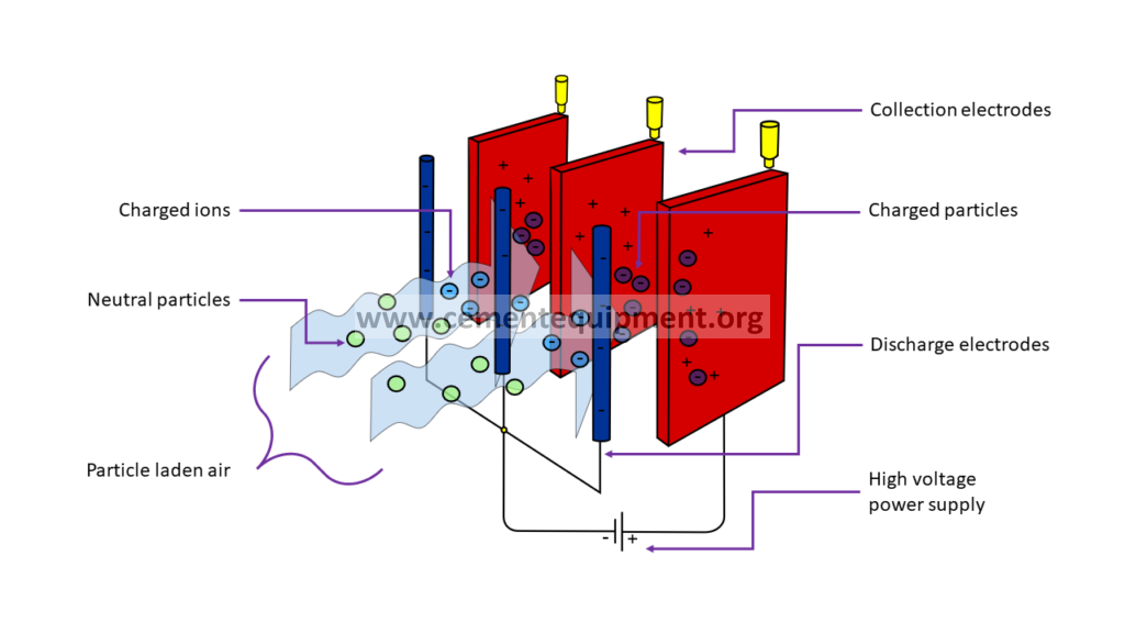
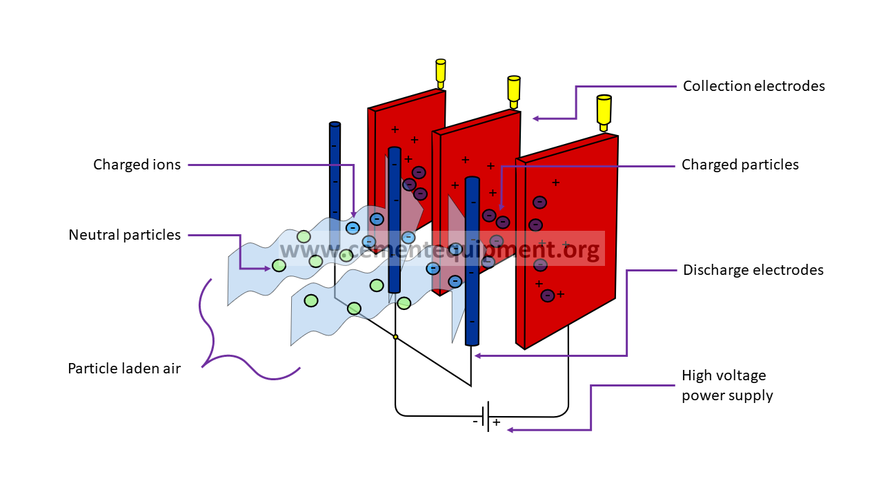
Quick answer
An ESP hopper level that keeps rising while the screw, rotary valve or drag conveyor appears to be running does not prove that dust is leaving the hopper. Separate four possibilities first: a false level indication, a discharge drive that is rotating without moving material, bridging or ratholing above the outlet, and a downstream restriction that prevents the discharge system from accepting dust. The fastest diagnosis is to verify actual mass flow and level independently, then work from the hopper throat downstream while preserving evidence from rapping cycles, motor load, dust condition and hopper temperature.
Problem / job
ESP hopper inventory rises toward a high-level alarm even though the dust-discharge equipment reports RUN, creating risk of re-entrainment, electrical-field disturbance or hopper overfilling.
Evidence
Capture level indication, independent level evidence, discharge motor current or torque, actual dust flow, rotary-valve/screw condition, hopper temperature/heaters, rapping sequence, downstream conveyor status and recent dust-property changes.
Decision
Separate instrumentation error, mechanical no-flow, bridging, air leakage and downstream restriction before increasing rapping or changing ESP electrical settings.
As-found evidence capture
Record the hopper level trend before resetting alarms or manually cycling discharge equipment. Note whether the level rises continuously, rises only after rapping, or falls briefly and then recovers. Record the running status, speed and motor current of the screw, rotary valve, double-flap valve, drag chain or pneumatic transfer equipment connected to the hopper. “Motor running” is only a command/status condition; it is not proof of material transfer.
Check the hopper heater status, wall-temperature trend where available, gas temperature, recent condensation or moisture events, and any change in raw material, fuel or dust loading. Record the timing of collecting-electrode and discharge-electrode rapping. If the high-level event follows every heavy rapping sequence, the hopper may be receiving dust faster than the discharge path can clear it, or a partially blocked outlet may only pass material intermittently.
Field checklist before touching ESP settings
- Verify hopper inventory independently of the level switch or transmitter.
- Confirm actual dust movement downstream; do not rely on RUN feedback alone.
- Trend discharge motor load through at least one normal rapping cycle.
- Check hopper heater status, wall condition and evidence of condensation.
- Confirm gates, couplings, screws, valves and shared downstream conveyors are mechanically available.
- Compare neighboring hoppers to separate a local blockage from a common downstream restriction.
- Preserve the as-found alarm and trend evidence before manual cycling.
Eight-step diagnostic workflow
1. Verify that the level signal represents real inventory
Cross-check the high-level indication using the plant-approved independent method. Inspect the level device for buildup, damaged wiring, false echoes, stuck mechanical movement or an incorrect switch state. Do not dismantle or enter the hopper while it is in service. If the independent evidence shows the hopper is not actually filling, correct the measurement path before changing discharge equipment.
2. Prove actual dust discharge
Observe the downstream receiving system and look for evidence of continuous dust flow during a safe operating period. Compare discharge motor load with a known healthy hopper or with the same unit at normal inventory. A rotating screw with unusually low load may be turning in an empty channel beneath a bridge; a high load may indicate compaction, a restriction or mechanical drag. Use trend comparison rather than a universal amperage limit.
3. Trace the material path from the hopper throat downstream
Work in process order: hopper throat, isolation gate, screw or feeder, rotary airlock or flap valve, transfer chute and the receiving conveyor or pneumatic line. Confirm that each device is open and mechanically coupled, not merely commanded to run. A sheared coupling, worn flight, slipping drive or closed gate can leave the motor status normal while actual transfer is near zero.
4. Check for bridging and ratholing
Dust can form a stable arch above the outlet, especially after cooling, moisture ingress, long residence time or changes in particle properties. Evidence includes rising level with low discharge load, sudden surges after vibration, and a hopper that empties only after a disturbance. Review hopper heating and insulation condition and inspect external temperature patterns where the plant procedure permits. Do not poke, hammer or enter a loaded hopper as an improvised remedy.
5. Check discharge-air sealing and false-air paths
Rotary valves, double-flap valves and other discharge devices often serve both as solids-transfer components and as air seals. Excessive leakage can disturb the hopper outlet, carry dust back into the ESP or reduce the effectiveness of a connected pneumatic conveying system. Inspect wear, seal condition and pressure relationships using approved methods. A valve can rotate normally while worn clearances prevent it from controlling air and solids correctly.
6. Check the downstream receiving capacity
Confirm that the screw conveyor, drag chain, bucket elevator or pneumatic line receiving ESP dust is available and not partially plugged. If several hoppers discharge into a common conveyor, one downstream restriction can cause multiple local high-level events. Compare neighboring hopper behavior: one affected hopper points toward a local outlet problem, while several hoppers rising together points toward a shared downstream bottleneck.
7. Correlate the event with rapping and dust loading
Rapping transfers collected dust from electrodes into the hopper. If level rises sharply after rapping and then clears slowly, compare the dust-release pulse with discharge capacity. Do not simply reduce rapping frequency to hide a discharge problem; poor rapping can increase electrode deposits and reduce collection performance. The correct solution is to make the discharge path reliably handle the dust released by the approved rapping strategy.
8. Verify recovery through a controlled operating cycle
After the identified fault is corrected, trend hopper level through several normal rapping and discharge cycles. Confirm that actual dust flow is visible or otherwise verified, motor load is repeatable, the downstream system remains available and the level returns to its normal operating pattern without manual intervention. Record the before/after evidence as a baseline for the next event.
Evidence-to-decision table
| Observed evidence | Most useful next check | Decision direction |
|---|---|---|
| High-level signal but no independent evidence of full hopper | Level-device condition and wiring | Repair measurement path first |
| Drive runs with unusually low load and little dust flow | Bridge/rathole and mechanical coupling | Investigate no-load rotation or outlet blockage |
| Drive load rises and downstream flow falls | Screw/valve restriction and downstream chute | Remove mechanical or material restriction |
| Several ESP hoppers rise together | Common conveyor or pneumatic receiving system | Prioritize shared downstream bottleneck |
| Level rises immediately after rapping | Dust-release pulse versus discharge capacity | Restore reliable discharge without masking rapping |
| Problem follows cold/wet operating period | Hopper heaters, insulation and dust condition | Investigate moisture/condensation-driven bridging |
| Rotary valve turns but hopper remains full | Rotor condition, air leakage and actual solids transfer | Verify valve is moving material, not only rotating |
Verification and return-to-service criteria
The hopper-discharge system is acceptable when the level trend remains stable through normal rapping cycles, actual solids transfer is independently verified, drive load is repeatable, and the downstream receiving system accepts the discharged dust without backup. Any repaired airlock or sealing device should also restore the intended air-separation function so that the solids path is not creating a new false-air or conveying problem.
Use the ESP manufacturer and plant operating procedure for level limits, heater settings, drive protection and allowable differential pressure. Hopper geometry, dust properties and discharge hardware differ widely, so this guide intentionally avoids universal numerical limits.
Common mistakes and repeat-failure traps
- Trusting RUN status as proof of flow: a motor can run with a failed coupling, worn screw or empty channel beneath a bridge.
- Resetting the level alarm without proving inventory: this removes useful evidence and can allow the hopper to continue filling.
- Reducing rapping to slow hopper filling: that can trade a discharge fault for poor electrode cleaning.
- Ignoring common downstream equipment: multiple hopper alarms may have one shared conveyor restriction.
- Using unsafe manual poking or hopper entry: follow isolation, stored-energy and confined-space procedures; loaded dust hoppers can release material suddenly.
- Replacing the level switch before checking dust buildup on it: contamination can mimic an instrument failure.
Related Infinity guides
Build a stronger cement technical library
The Infinity for Cement Organization technical package contains 900+ technical files for cement professionals. It is a one-time $249.99 purchase, with instant download immediately after payment and lifetime updates forever at no additional cost.