Operating and Maintenance of Electrostatic Precipitator in Cement Industries
CLICK HERE NOW TO DOWNLOAD MOST IMPORTANT BOOKS IN CEMENT INDUSTRY + PRACTICAL EXCEL SHEETS TO HELP YOU IN YOUR DAILY WORK
Abdulgaffar Doddamani,
Assistant Professor, College of Horticulture Engineering and Food Technology Bagalkot, Karnataka, India
Email: [email protected]
ABSTRACT
The cement process industries utilizing raw materials for the production of cement and these raw materials are burnt in the kiln at the temperature around 1400°C. During cement manufacturing process air gets pollute which includes particulate matter NOx, SOx., CO, CO2, hydrocarbons and other substances are released to the atmosphere. The burning of organic material such as coal oil wastes in kilns produces an exhaust gas. Without secondary purifying treatment, these gases cannot be released into the atmosphere due to environmental protection. This problem can be overcome from the device called electrostatic precipitation which is an efficient technique for removing entrained particulate contaminants from exhaust gases and is extensively used in these industries to limit particulate emanations. In outlook of this, information on construction, working, design, erection, commissioning, operation, maintenance and challenges that are being faced while carrying out the erection of the various electrical equipment’s, testing and commissioning of the Electrostatic precipitator are explained in this paper.
Keywords:Electrostatic precipitator, Ionization, Transformer Rectifier Unit, Electronic Controller
Citation of this article
Abdulgaffar Doddamani. Operating and Maintenance of Electrostatic Precipitator in Cement Industries.Int. Arch. App. Sci. Technol; Vol 9 [4] December 2018. 101-110
INTRODUCTION
In recent years, there is an increasing awareness towards problems associated with atmospheric pollution; subsequently, most industrialised nations have ratified regulation to limit uncontrolled emissions from all sources. This legislation is continuously look over and becoming more rigid, such that particulate emissions, in particular, are presently controlled to a maximum of 50 mg Nm−3 for inert materials and 10 mg Nm−3 for substances deliberated dangerous to health and it is suspected that within the next decade these values will be further reduced.one of the best method to eliminate these harmful gases from to atmosphere an electrostatic precipitator is used. In 1920 first pulverised coal steam raising plant is installation where some 90% of the ash can be carried forward with the waste gases, in the power generation industry electrostatic precipitator has been almost universally used to control particulate emissions. To meet current emission regulations, fly ash collection efficiencies in excess of 99.8 per cent can be required when handling gas flows of up to 1000 am3 s−1.
As cement industries uses the raw materials for production of cement and these raw materials are burnt in the kiln at the temperature around 1400°C. Today air get pollutes allied with cement manufacturing includes particulate substance NOx. SOx., CO, CO2 hydrocarbons and other substances. Burning of organic material such as coal oil wastes in kilns produces exhaust gas that cannot be released in to the atmosphere because of environmental protection without a purifying secondary treatment. International and national authorities specify concentration limits for dust and certain chemical compounds in guide lines. Environment protection has become major issue nowadays and authorities are setting more strict limits, one of which is the emissions from the industrial plants of solid particulate and other gaseous pollutants. For the production of electricity many countries around the world including India are depending on the coal and other fossil fuels. During burning of fossil fuels, particularly coal, emission of fly ash taken place. Ash is mineral matter present it the fuel. 60-80% of ash leaves with the flue gas from a pulverized coal unit [3]. An electrostatic precipitators (ESP) are extremely effective filtrating device that will accumulate the particles and it can easily remove fine particulate matter such as dust and smoke from the air stream by using the force of an induced electrostatic charge from the transformer rectifier unit which is located at the top of the ESP. Nowadays these ESPs are gaining importance as to obtain the environmental clearance for setting up of new industrial plants and green environment.
The ideal features of the electrostatic precipitation process, which are required to remove the particulates, are as follows.
(1) Versatility – compelling execution on an extensive variety of modern procedures. Can be intended to meet any required productivity and estimated for any gas flow rate.
(2) Designs can be created to cover a temperature extend from encompassing up to 850 °C. (3) Can gather particles over the complete size range spectrum.
(4) Dust is normally recouped in its original state. In any case, plants can be intended to work as a wet phase device if required, especially for gases near, or at, dew point temperature.
(5) Low-pressure loss – normally less than 1 mbar.
(6) Acceptable electrical power utilization for the required efficient level. (7) Robust and reliable construction – life expectancy >20 years.
(8) Low maintenance requirements.
DEFINITION OF ELECTROSTATIC PRECIPITATOR
“An electrostatic precipitator is a large, industrial emission-control unit. It is designed to trap and remove dust particles from the exhaust gas stream of an industrial process [2]. Electrostatic Precipitators are used for the collection of dusts, mists and fumes.
These are defined as follows:
- Dust: solid particles from 0.1 to 100 µm in diameter.
- Mist: liquid droplets suspended in a gas.
- Fume: solid or liquid particles formed by condensation from a vapour.
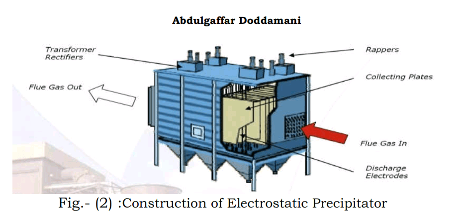
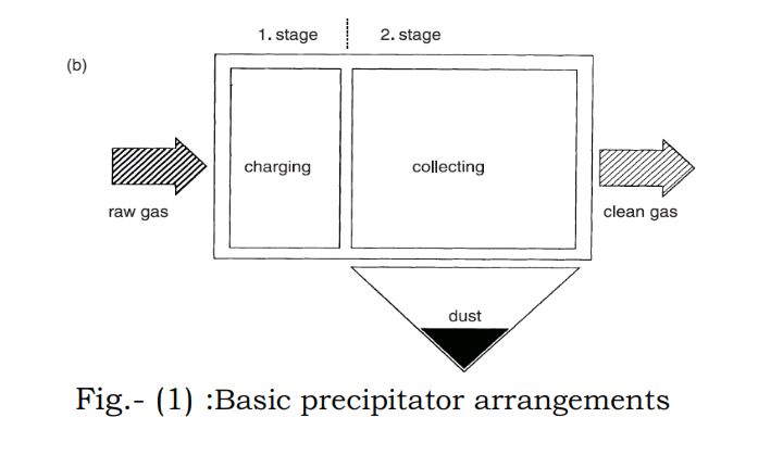
Construction of a Precipitator: The basic ESP contains a casing with inlet transition, gas distribution devices, outlet transitions, dust collection, hoppers and support steel. The casing encloses and supports the internal equipment such as collection surfaces, discharge electrodes and rapping devices.
BASIC PRINCIPLE:
There are three main stages for the developments of electrostatic precipitator namely Particle charging, Transport and Collection. To describe all these stages determines to take a great number of basic phenomena into account from a physical point of view when they occurred.
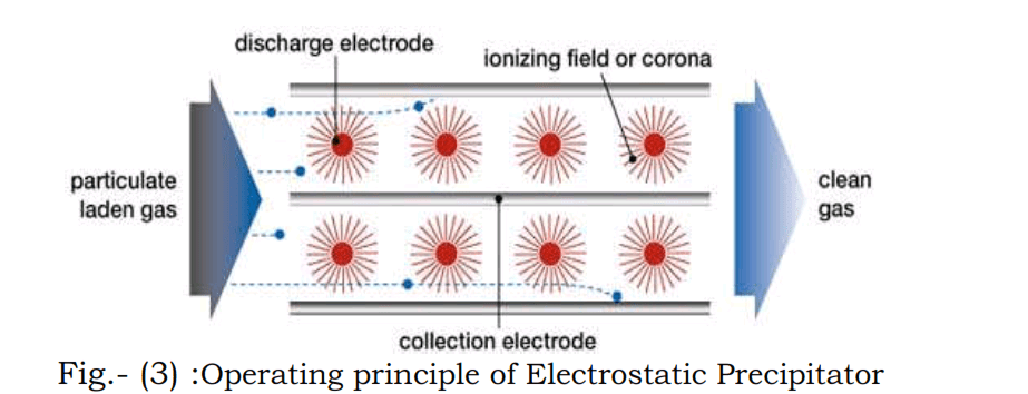
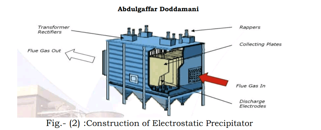
Fig.- (3) :Operating principle of Electrostatic Precipitator
The flue gas loaded with fly ash is sent through pipes having negatively charged plates which give the particles a negative charge. The particles are then routed past positively charged plates, or grounded plates, which attract the now negatively charged ash particles. The particles stick to the positive plates until they are collected. The air that leaves the plates is then clean from harmful pollutants.
Main Stages of Electrostatic Precipitator: There are three main stages/processes of electrostatic precipitator (ESP) [2].
- Particle Charging: Particle charging is the first and notable beginning in processes. As the voltage applied on, precipitator reach onset value and the space inside is divided into ionization region and drift region. The electric field magnitude around the negative electrode is so strong that the electrons escape from molecule under the influence of electric field, the positive ions move towards the corona, whiles the negative ions and electrons towards the collecting plates.
- Transport: In the moving way, under the influence of electric field, negative ions adhere and charge the particles, make the particles be forced towards collecting-plate.
- Particle Collection: As soon as the particles reach the plate, they will be neutralized and packed by the succeeded ones subsequently. The continuous process happens, as a result, particles are collected on the collecting plate
Types of electrostatic precipitator:
There are two types of electrostatic precipitator
- Dry type Electrostatic Precipitator
- Wet type Electrostatic Precipitator
In the cement industries the kiln cooler ESP uses the dry type, hence the meticulous study is focused on Dry type ESP, the dry type is the most common it collects and removes the particulate matter in a dry state.
OPERATION:
A dry type ESP for removing dust particulates from a flowing gas stream and encompasses of an upright cylindrical vessel, each precipitator stage have particulate charging electrodes and accompanying collector electrodes, arranged in a controlled flow path. A dust hopper located beneath each stage and dust chutes extending from the hopper to discharge outlets (end mass conveyor) at the bottom of the vessel. The particles will be drawn towards plates hanging on the side of the devices, where they will collect. Periodically, the plates will be struck by a hammer or something like it, or vibrated [2].
Components:
The major precipitator components that accomplished these activities are as follows
- Discharge electrodes
- Power supply and controls
- Rapping systems
- Hoppers and dust handling
Discharge electrodes: which emit the charging current and provide voltage that generates an electrical field between the discharge electrodes and the collecting plates.
Power supply and controls: it is designed to provide voltage to the electrical field (or bus section) at the highest possible level.
Rapping systems: rappers are time-controlled systems provided for removing dust from the collecting plates and the discharge electrodes
Hoppers and dust handling: Precipitator’s hoppers are designed to completely discharge dust load on demand
Typical activities:
There are six typically activities that takes place in electrostatic precipitator
- Ionization- charging of particles.
- Migration- transporting the charge particles to collecting surface
- Collection- precipitation of the charge particles onto the collecting surfaces.
- Charge dissipation- neutralizing the charged particles on the collecting surfaces.
- Particle dislodging: removing the particles from the collecting surface to the hopper.
- Particle removal: conveying the particles from the hopper to a disposal point.
Design Consideration:
The following parameters to be considered while designing any precipitator
- Precipitator Size: When sizing the precipitator, it h important to provide a W that wil maintain an acceptable gas velocity
- Gas Velocity Distribution: improving gas velocity distribution in the precipitator reduces particle re-entrainment and boosts precipitator efficiency.
- Gas velocity distribution can be modified by using flow control devices end baffle.
- Particle Re-Entrainment: Minimizing re-entrainment of dust particles is important to improvement of precipitator efficiency.
- Corona Power: An optimum amount of power should be supplied taking consideration the cost factor and the required efficiency.
Description of Electrostatic Precipitator:
During normal operation the flue gas passes through the electrostatic precipitator, in which the entrained ash or dust particles are removed by the process of electrical force applied within it and the clean gas emerged to the atmosphere through induced draft fan and stack. The electrostatic precipitator comprises with number of dust collecting plates commonly known as collecting electrodes, placed in rows and kept in parallel in order to form a multi parallel path to pass the gas through it. The discharge electrodes are freely suspended through insulators within this path In series at a pre calculated distance from each other and that of collecting electrodes. The collecting and discharge assemblies are housed within a mild steel casing complete with hoppers properly lagged with insulating material and duly clad with aluminium or galvanized iron sheet to avoid loss of system heat thus to eliminate the chance of condensation.
In the precipitator, a high voltage DC is impressed on the discharge electrode assembly from a high voltage transformer rectifier unit with set of control logic and interlocking system. The necessary primary AC supply voltage and control feed backs for the transformer rectifier unit are fed from the control panel, housed separately nearby, containing all the necessary control gears for the operation.
The gas as entering to the precipitator comes under the of high static electric field set up by the high potential difference of discharge and collecting electrodes. Corona generated in the system causes the solid mass in the gas to get ionized. The ionized solid mass, due to consistent potential difference, migrates towards the collecting electrodes and adhere on it releasing/ground the charge. Thus the dust particles are separated from the dirty gas. The clean gas thus passes out at the precipitator [3].
The collected dust is removed from the collecting plates by rapping them on bottom end at an interval causing the dust to dislodge and to fall in to the hopper beneath the collecting fields. Rapping is also applied to the discharge electrode to remove the dust deposited on them due to positively charged particles for better and consistent corona generation.
Collecting Electrode:
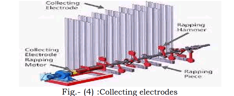
Fig.- (4) :Collecting electrodes
The collecting electrodes shown in Fig.6 are fabricated out of 1.25mm thick cold rolled mild steel sheet as per is 513. The collecting electrodes are having typical corrugated type configuration, design in accordance with the profile of corona generation by the discharge electrodes and the gas velocity for quiescent zone formation. These electrodes are suspended from collecting electrode fixing assembly located at top, supported and equally spaced by top plate carrier beam.
The bottom end of the plates is joined together with bottom fixing assembly by fastener. The top plate carrier beams are fitted with the main structure of the electrostatic precipitator casing at roof level. At the bottom fixing assembly at one spacer plates are provided to ensure that the relative spacing of 400mm between each plate is maintained correctly and other end of the bars are fitted with rapping anvils.
Discharge Electrode:
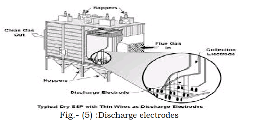
The Pipe and fin type discharge electrodes are fabricated from ere pipe with a typify fins, made of cold roiled anile sheet, spot welded on both sides with copper deposition, at pre calculated spacing. This type of electrodes provides a robust rigid assembly which is virtually unbreakable, resistant to erosion and corrosion and has high emission characteristic under all concentration of dust content in gas. These discharge electrodes are suspended between the collecting electrode rows from a hanger consisting of mild steel section grids to ensure a high degree on alignment with the collecting electrodes. The top grids are in turn freely suspended from HV insulators mounted outside the gas stream on the precipitator roof top from 3 points to keep the discharge electrode system separated from the casing. The bottom grids of discharge electrode are freely suspended below the collecting electrode bottom fixing bar the end of the discharge electrodes are fixed with a frame celled bottom grid by nuts, bolts and spacer to maintain the spacing and the straightness of discharge electrodes. The special features of discharge electrodes are:
- Optimum corona effects ensure optimum charging of all particles and as a result superior and constant cleaning efficiency is achieved.
- Improved cleaning effect by the vibration set up by the rapping system is transmitted over the entire length of each and every electrode.
- Rigid electrodes are “unbreakable” and “self-aligning” type and are not subject to spark erosion or mechanical wear, which are the principle cause of failure. Such electrodes do not require any replacement during the entire life of precipitator.
Gas Distribution Sheet: For proper performance and functioning of an electrostatic precipitator the velocity of the gas passing through the electrical fields should be uniform. For these reasons the inlet of the precipitator and outlet is provided with gas distribution arrangement. The gas distribution arrangement consists of perforated plates placed in series for inlet. In addition there is rapping system of flail hammer type to clean the perforated plate.
Collecting Electrode Rapping: Collecting electrode rapping mechanism consists of flail hammer rapping arrangement in the bottom plane of the plates. Rapping is done at a position selected to achieve the most efficient oscillatory as well as vibratory movement of collecting plates for dust removal. The hammers and levers are fitted on a shaft, which is extended throughout the length across the collecting fields supported by intermediate bearings fitted on bearing bracket and coupled with geared motor for rotation. Rapping for each set of collecting electrodes of each field is thus separate and allows the frequency of rapping to be adjusted separately. The sequence of rapping is controlled by means of microprocessor based programmer, so that under no circumstances, any two rapping of any field could run simultaneously. The frequency of rapping is regulated by Programming the rapper timing depending on the type and quantity of dust deposition on collecting plates. Each row of collecting is struck by hammer sequentially during each rapping cycle with flail hammer on gravity fall to impart the required momentum. The film of collected dust is effectively sheared off from the plate surface by vibro-oscillatory acceleration and remains close to the plates while falling to the dust storage hoppers. This feature limits the re-entrainment of dust in the main stream ensuring the high collecting efficiency. All shaft entry points on the casing are sealed by graphite asbestos gland packing in the staffing box to prevent false air entry.
Discharge Electrode Rapping: The mechanism consists of a primarily the ratchet and wheel mechanism for dropping action on anvil followed by a steel shaft with hammer arrangement. The shaft is mounted on discharge electrode top grid hanging above the collecting plates. The hammers are bolted to the shaft of an equal intervals corresponding to the anvil connected to a pair of top grid holding angles along the grid.
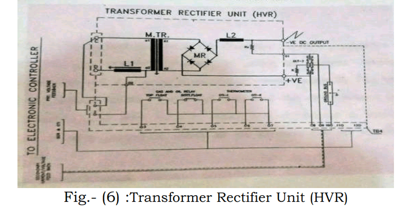
DESCRIPTION OF POWER CIRCUIT
The SCR controlled precipitator power supply system consists of two units [2].
1-Transformer Rectifier Unit
2- Electronic Controller
Transformer rectifier Unit: The TR unit consists of HT transformer Fig.6, linear reactor and rectifier diode stack with voltage sharing resistor, storage condenser, HT feedback resistors and high frequency choke. All these components are oil immersed and hosed in a tank. This rectifier stack consists of number of silicon diodes connected in series by means of suitable voltage sharing resistor. The linear reactor L1 connected in series with primary of main transformer for reducing the short circuit currents under sparking/ arcing conditions. L2 is high frequency reactor used for limiting the discharge current due to transformer capacitance during sparking. The shunt resistor is secondary current sensing resistor and is connected in positive terminal of rectifier and GND. Over voltage glow tube is used as backup protection in case of shunt open. High voltage DC voltage to micro ampere calibrated in DC kv measures the DC output voltage. The HV resistance column is located in the TRU and meter is mounted on the front panel of the control cubicle.
Electronic controller: The components in the electronic controller are fig.8. SW1 is the main fuse switch unit consisting of switch SW1 and HRC fuses. Auxiliary transformer TR2 is provided for cubicle light and socket supply. This transformer is provided with fuse FS3 and FS4 on input side. When the auxiliary power supply of 230V AC is made available through this transformer, the cubicle light switches ON in case of front door open. The cubicle light is interlocked to the front door by means of micro switch MS1 when the main switch fuse unit. SW1 is made ON; the power is made available to auxiliary transformers (TR1&TR3). Various interlocks are provided in the contactor circuit so that in case of faults, the contactor: will be switched OFF. When the contactor is switched ON, the AC supply is made available to the SCR regulator. This single phase regulator consists of SCR1-SCR2 connected back to back. The snubber network consists of R1a, C1a, R1b and C1b provided across the SCRs for surge protection. Also input surge suppression network is provided for the AC regulator protection. Current transformers (CT1-CT2) are sensing primary current to monitor primary current and sensing primary overload through thermal over load relay. VM1 is the AC voltmeter, which monitor the primary voltage of the transformer. DC meters are provided across the shunt and HT resistance column and are shown in circuit as AM2, All the interconnection for remote indication and alarm are wired to the terminal block TB1.
MAINTENANCE
Maintenance of electrostatic precipitator is therefore mainly a preventive nature. The rectifier requires general maintenance, in order to prevent breakdown. The transformer rectifier set should be inspected at regular intervals. The length of this interval is determined by the nature of duty and the environment (presence of vibration, moisture and dust etc.) in which the equipment is installed. Under favourable condition a period as much as six months can be allowed between inspections [2]
Routine maintenance of an ESP is very simple. The only maintenance requirement is the periodic lubrication of external equipment on an ESP, as set forth in the maintenance manual, are drive elements of collecting and emitting rapping systems. These may be motors, gear reducers, vibrators, air valves and cylinders, chain drives or similar mechanical equipment. Hence, most so-called maintenance work is really the thorough inspection of components to ascertain that they are functioning properly.
5.1 Transformer rectifier section:
- HV Bushing insulator: HV Bushing should be cleaned to prevent the coating of dust.
- Oil tank surface: clean the outside of the oil tank of transformer rectifier set to prevent coating of dirt and dust which will reduce the cooling.
- Oil Check: for every three months the oil level should be checked. Observation has to be made and marking of level should be done. Any loss of oil must be replaced.
- Draining of Oil: Approximately for every two years extracted oil samples are tested for insulation resistance, breakdown value, and water content and foreign matters; the electrical breakdown value must be equal to 50kv for 2.5mm gap. Whether the oil contains water must be ascertained by crackle test. While heating the oil to 120°C crackling noise is heard then the transformer oil must be regenerated, while draining the oil for sample it should be drained carefully using proper oil draining device which can be screwed in the drain valve after removal of drain valve cap.
- Air Dehumidifier: Renew the silica gel refining every one to five years according to the moisture content in the ambient temperature.
Critical Checks of Electrostatic Precipitator:
Pre Commissioning Check-up of Electrostatic Precipitator [2] Mechanical Checks
- General
- Rapping
General:
1- All access doors for proper sealing.
2- All negative suspensions, frames and discharge electrodes straightness and its alignment.
3- All collecting electrode plates for straightness, alignment and for adequate side expansion allowance.
4- All fields and hoppers for debris/foreign materials.
Rapping:
1- All collecting electrodes rapping shafts for alignment and turn manually for freeness
2- All hammers, connecting brackets for proper bolting/ welding and free fall of hammers.
3- Fill the geared boxes of collecting and discharge rapping with oil.
4- All discharge electrode rapping shafts for alignment and turn manually.
5- Set stoke on discharge electrode and check that rapping shafts are engaged correctly.
Electrical Checks:
- All earthing system.
- Heaters and thermostats. Set the thermostat to 120%.
- The directions of rotation of rapper motor.
- All cables and terminations.
- Check and commissioning of T/R set through manufacturer’s personal.
- Set rapping timings for collecting and discharge electrodes.
- Hopper level indicator with its interlocking with T/R sets.
Checks related to Motor Control Centre:
- Earthing and megarring of the panel
- All disconnected wires and loose terminals.
- Correctness of rated fuses.
- Fused defective and missing indication lamp and meters.
- Transformer rectifier Checks
- Ensure all is at correct level in the conservator
- Silica gel in the breather cartridge is blue
- No oil leakage through transformer Joints drain plug through H T bushings or top end.
- All gasket and screw of the terminal boxes are filled properly.
ROUTINE CHECK UP Daily Routine Check Up:
1- The Voltage/ Current input and output to each stage of precipitation should be checked.
2- The cause of unusual reading should be investigated. Better to maintain the hourly log book. . Normal current rating should be noted for each rapping motors.
3- Check all lights on the control panels to indicate normal functioning.
4- Check the dust disposal system functioning properly.
Weekly Routine Check Up:
- Check the drive mechanism for the electrode rapping gear. Obtain access to roof housing by switching off appropriate H.V. supply and obtaining castle interlock key. Before opening the housing door, Be sure that the ESP fields are earthed properly.
Monthly Routine Check Up:
1- Carry out daily and weekly routine Checks
2- Check oil levels of HV transformer rectifier tank conservators; fill up as necessary with recommended oil, the silica gel in breather cartridges. if the crystals become white or pink, cartridge should be replaced. Reactivate the crystals by placing it over at 1350 C until crystal becomes blue.
3- Lubricate all external bearings.
4- Check and clean high level probe fitted on ESP Hoppers.
Advantage and Disadvantages of ESP.
Advantages:
- High collection efficiency.
- Low maintenance and operating costs.
- Handles large volume of high temperature gas. They can be designed for a wide range of gas temperatures, and can handle high temperatures, up to 700°C (1300°F).
- Negligible treatment time. Easy cleaning.
- They have long useful life.
- Versatility-effective performance on a wide range of industrial processes.
- Low pressure loss-typically less than 1bar and also capable of operating under high pressure [to 1,030 kPa (150 psi)] or vacuum conditions.
- Electrostatic Precipitator can be installed on any existing wet scrubber installation.
Disadvantages:
- High initial cost.
- Certain particulates are difficult to collect due to extremely high or low resistivity characteristics.
- Dry ESPs are not recommended for removing sticky or moist particles. Ozone is produced by the negatively charged electrode during gas ionization.
- There can be an explosion hazard when treating combustible gases and/or collecting combustible particulates.
- Relatively sophisticated maintenance personnel are required, as well as special precautions to safeguard personnel from the high voltage.
- More space requirement. Possible explosion hazards. Large maintenance requirement.
- Production of Toxic gases such as ozone and oxides of nitrogen may be produced by negatively charged discharge electrodes.
APPLICATION OF ELECTROSTATIC PRECIPITATORS:
- Pulp and paper mills, Non-ferrous metal industry, Chemical industry, Public buildings and areas
- Cement recovery furnace, steel plant for cleaning Blast furnace gas.
- Removing tars from coke oven, sulphuric acid (Pyrite raw material ) , phosphoricacid plant
- Petroleum industry for recovery of catalyst, carbon black, thermal power plant.
CONCLUSION
The cement, power generation, chemical other processing industries produces unwanted fine particulate matter NOx, SOx, CO, CO2 hydrocarbons and other substances which are released to the atmosphere. This are very harmful to the human being to overcome from this problem an electrostatic precipitation are used which is an efficient technique for removing entrained particulate contaminants from exhaust gases and is extensively used in these industries to limit particulate emissions. For smooth operation of an electrostatic precipitator, it is necessary to have a routine maintenance on the daily, weekly and monthly basis in order to continuous performance are explained in this paper. In view of this, information on construction, working, design, erection, commissioning, operation, and maintenance of electrostatic precipitators are explained in this paper.
REFERENCES
XU Guosheng, XU Libo(2008). “Five Stages Electrostatic Precipitator Principles and Application”
11th International Conference on Electrostatic Precipitation,Hangzhou, pp 70-72.
United States Environmental Protection Agency (EPA) (1985). “Operation and Maintenance Manual for Electrostatic Precipitators” EPA/625/1- 85/017.
- S. Oglesby. (1983).Tang Tianyou Translating, Electrical Precipitator.China Water-Power Power Press.
H E Jian, XU Guosheng, YU Guoqiang (2008). “V-I Characteristic Principle of Electrostatic Precipitator” 11th International Conference on Electrostatic Precipitation,0ngzhou, pp 370-373. YU Fu sheng, HAN Xu, LI Xionghao, HAI Jiang, DU Rongli, LI Zaishi,(2008). Study on Improving the Performance of Electrostatic Precipitator in the Large-scale Semi-dry Flue Gas Desulfurization System”,11th International Conference on Electrostatic Precipitation,Hangzhou, pp 527-530. Benmabrouk. Zaineb, Ben Hamed. Mouna,Lassaad. Sbita (2011). “Wireless Control for an Induction Motor”,International Journal of Electrical and Electronics Engineering, vol.5,no. 1, 20- 25.
Theodore, L. (2008).‘Electrostatic Precipitators’ in “Air Pollution Control Equipment Calculations”, Wiley.
CLICK HERE NOW TO DOWNLOAD MOST IMPORTANT BOOKS IN CEMENT INDUSTRY + PRACTICAL EXCEL SHEETS TO HELP YOU IN YOUR DAILY WORK