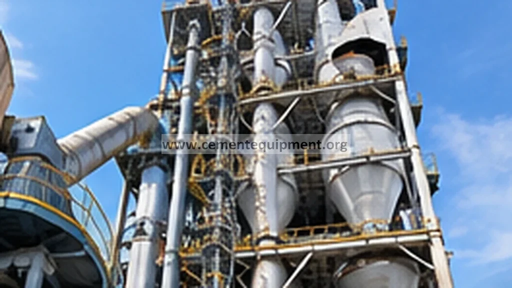

A blocked or leaking preheater pressure impulse line can make a healthy cyclone look unstable, overloaded or starved. Before changing dampers, fan speed or feed, compare the suspect transmitter with adjacent pressure points and process behavior, inspect the pressure tapping for coating, verify the impulse tube is open and leak-free, then confirm zero/span or transmitter health. The diagnostic goal is to prove the pressure signal before changing the kiln process.
Separate a false preheater pressure reading from a real draft, blockage or cyclone-separation problem.
Use adjacent pressure trends, ID-fan condition, temperature, O2/CO where relevant, tapping condition, impulse-line integrity and transmitter response.
Do not tune the process until the pressure measurement agrees with independent process evidence.
Fast diagnostic order
- Validate the signal before tuning the process: compare the suspect pressure with adjacent stages, ID-fan condition, temperature and gas-analysis trends.
- Inspect the measurement path: clean the process tapping safely and check the impulse line for blockage, leaks, condensate traps and kinks.
- Verify purge condition: confirm the installed purge flow is neither too low nor high enough to bias the reading.
- Prove the transmitter and DCS scaling: check zero/reference response, engineering units and range configuration.
- Only then diagnose the cyclone/process: if the signal is healthy, investigate restriction, meal loading, dip tube, flap valves and false air.
Preserve the pressure trend before cleaning the tapping
Record: suspect pressure value and trend; upstream/downstream or neighboring-stage pressures; kiln feed; ID-fan speed/damper; gas temperature; O2/CO and draft where used by the plant; whether the signal is frozen, noisy or slowly drifting; recent coating history; and any maintenance on the transmitter or impulse line.
A frozen value during obvious process changes is a strong instrumentation clue. A true process restriction usually affects more than one independent signal.
1. Compare the suspect point with neighboring process evidence
Do not start by removing the transmitter. Compare the pressure with adjacent cyclone stages, riser or kiln-inlet draft points and the ID-fan operating condition. If one signal moves in the opposite direction from the rest of the preheater without supporting temperature, fan or gas-analysis evidence, the measurement path becomes the first suspect.
2. Inspect the process pressure tapping for coating
Cement raw meal, alkali/chloride deposits and sticky kiln dust can build around pressure tappings. A partially blocked tapping acts like a restriction and can create lag; a fully blocked tapping can trap pressure and make the signal appear frozen. Isolate and clean only according to the plant procedure because hot gas, dust and pressure can be released. Document the material removed because recurrent coating points to a process or tapping-design issue.
3. Check the impulse line for blockage, leakage and low points
Inspect tubing routing, fittings and supports. Kinks, packed dust, condensate traps, loose compression fittings and cracked flexible sections can all distort the signal. A leak may pull the indicated pressure toward atmosphere; a plugged line can create a slow or fixed response. Keep the line slope and purge arrangement consistent with the installed design.
4. Verify purge-air condition where a purge system is used
Some preheater pressure points use a small purge to keep dust out of the tapping. Too little purge allows plugging; excessive purge can bias the measurement. Check the purge rotameter, regulator, restriction and common supply. Compare with the plant/OEM setting rather than using one generic purge flow for every point.
5. Prove transmitter response and scaling
After the tapping and line are confirmed open, check transmitter zero/reference condition and response using the approved calibration method. Verify engineering units and DCS scaling. A transmitter can be electrically healthy while the displayed range is wrong because of configuration or scaling changes after replacement.
6. Separate instrument lag from real cyclone restriction
If the pressure responds correctly after cleaning but the stage pressure remains abnormal, return to the process diagnosis: cyclone dip-tube condition, material buildup, flap-valve behavior, gas-flow distribution, meal loading and false air. The measurement repair may reveal a real process problem that was previously hidden.
7. Trend recurrence frequency
Repeated blockage at the same tapping is itself diagnostic. Record hours between cleanings, deposit type and operating condition. Recurrent plugging may justify a revised tapping geometry, purge arrangement or maintenance interval, but any modification should preserve the transmitter’s measurement accuracy and follow plant engineering control.
Pressure-signal diagnostic matrix
| Observed pattern | Likely direction | Next check |
|---|---|---|
| Signal frozen while process changes | Blocked tapping/line or transmitter issue | Tapping, impulse line, transmitter response |
| Signal drifts slowly after step change | Partial restriction or trapped condensate | Line routing, low points, partial plugging |
| Reading near atmosphere while adjacent points normal | Leak/open fitting/scaling fault | Fittings, tubing, DCS range |
| Reading abnormal with matching fan/temperature trends | Likely real process change | Cyclone restriction, draft, meal loading |
| Problem returns soon after cleaning | Deposit/purge/design recurrence | Deposit type, purge flow, tapping geometry |
Instrument sanity check before process intervention
When possible, compare the suspect indication with a calibrated portable reference or a second approved measurement path. Check whether the transmitter output changes smoothly and whether the DCS value matches the local signal. This avoids a common failure mode in troubleshooting: repairing the process around a bad measurement. Any temporary test connection must follow the site’s hot-gas, dust and pressure safety procedure and be removed after verification.
Common mistakes
- Changing ID-fan or damper settings before proving the pressure signal.
- Blowing a tapping without following the safe isolation procedure.
- Using excessive purge air that biases the measurement.
- Replacing the transmitter while leaving a blocked process tapping.
- Ignoring DCS scaling after transmitter replacement.
Return-to-service verification
After cleaning or calibration, verify that the signal responds smoothly to a real process change and agrees directionally with neighboring draft points and fan behavior. Acceptance means no frozen or erratic response, no impulse-line leakage, stable purge condition where fitted, correct engineering units and a pressure trend consistent with the plant’s known-good preheater profile. Preserve before/after trends for the next recurrence review.
Frequently asked troubleshooting questions
Can a blocked preheater pressure tapping make the process look unstable?
Yes. A partial blockage can create lag and a full blockage can trap a false value, causing operators to react to an instrument problem as if it were a real draft change.
How do you distinguish a bad pressure signal from a real cyclone restriction?
Compare the suspect point with neighboring pressures, fan condition, temperature and other process evidence. A true restriction usually affects more than one independent signal.
Should purge air be increased whenever a tapping plugs?
No. Too much purge can bias the measurement. Verify the tapping, impulse line, purge hardware and the installed plant/OEM purge setting first.
Related Infinity technical guides
References
Pressure-tapping maintenance, purge flow and transmitter calibration must follow the installed instrument and preheater OEM procedures. Use the plant’s stable stage-pressure profile and adjacent independent process measurements as the primary diagnostic baseline.