Quick answer
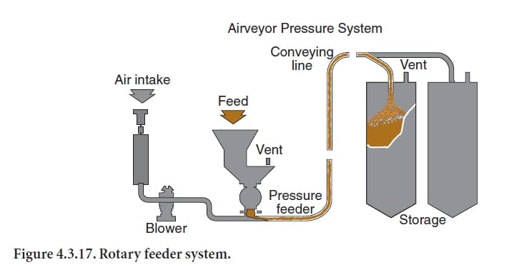
Blowback from a pneumatic-conveying line into the hopper above a rotary feeder usually means the pressure differential across the valve is greater than the sealing performance of the rotor clearances, or that downstream resistance has increased. Diagnose it with pressure, airflow, rotor-clearance, speed and material-flow evidence before changing the feeder. Worn tips, housing wear, excessive line pressure, downstream blockage, poor venting and incorrect rotor speed can all produce the same visible symptom.
Problem / job
Dust or air pulses back into the feed hopper, disturbing material entry and sometimes creating dust leakage at the hopper top.
Evidence
Capture upstream hopper pressure, downstream conveying pressure, blower load, rotor speed, motor current, throughput and measured rotor clearances.
Decision
Separate excessive system backpressure from worn sealing clearances, incorrect speed, blocked downstream equipment or inadequate hopper venting.
As-found evidence capture
Record the condition while the blowback is occurring. Note whether it appears continuously, only at high feed rate, during line startup, after a route change or when a receiving filter begins to load. Trend conveying pressure, blower current, solids feed rate, rotor speed and any hopper pressure indication. Observe whether dust rises through the hopper continuously or in pulses.
After safe isolation, inspect the feeder for rotor-tip and end-plate wear, housing scoring, buildup in pockets, damaged seals and foreign-object marks. Measure clearances at several positions rather than relying on one reading.
Seven-step diagnostic workflow
1. Confirm the downstream pressure level
Compare actual conveying pressure with the historical baseline at similar feed. If the system now operates at higher pressure, investigate downstream resistance before assuming the feeder alone has deteriorated.
2. Correlate blowback with load
If blowback increases sharply as solids feed rises, the system may be approaching its pressure or capacity limit. If blowback exists even at very low feed, worn clearances or severe line restriction become more likely.
3. Inspect and measure rotor clearances
Check rotor tips, end clearances and housing condition. Uniform wear suggests normal abrasive deterioration; one-sided wear can indicate bearing, alignment, shaft or housing problems. Use the valve manufacturer’s approved clearance limits.
4. Verify rotor speed
Too high a speed may reduce pocket filling and create more leakage relative to useful solids transfer; too low a speed may also increase leakage per unit of conveyed material. Verify actual shaft rpm rather than only the drive command.
5. Check downstream restrictions
Inspect elbows, diverters, receiver, filters and discharge equipment. A blocked or overloaded receiver can elevate pressure and force conveying air backward through a feeder that previously operated satisfactorily.
6. Check hopper venting and feed condition
The hopper must release displaced air and allow stable material entry. Restricted venting can amplify dusting and make blowback appear worse. Also inspect bridging, ratholing or erratic refill that may cause the feeder pockets to load unevenly.
7. Verify the repair under representative load
After correcting the dominant cause, repeat the original operating condition. Confirm that hopper pressure remains controlled, blowback is absent or reduced to normal, throughput is restored and conveying pressure remains stable.
Evidence-to-decision table
| Evidence | Likely direction | Next check |
|---|---|---|
| Blowback rises with downstream pressure | System restriction/capacity issue | Line, receiver and filter |
| Large uniform rotor clearance | Abrasive wear | Rotor tips/housing repair decision |
| One-sided wear marks | Alignment, bearing or shaft problem | Runout and bearing condition |
| Normal clearances but poor pocket filling | Speed or feed issue | Actual rpm and hopper flow |
| Dusting worsens with closed/dirty vent path | Hopper venting problem | Vent/filter condition |
Return-to-service acceptance criteria
Return the feeder to normal service only when the rotor turns freely, measured clearances are within approved limits, hopper venting is functional, downstream pressure is controlled and representative throughput can be achieved without abnormal blowback. Record the final clearances, pressure and motor-current baseline for future comparison.
Common mistakes
Do not simply increase blower pressure to overcome unstable conveying. Do not replace rotor tips without investigating why wear is asymmetric. Do not ignore receiver-filter differential pressure. Do not change rotor speed without measuring the result. Finally, do not block hopper vents to contain dust; that can worsen pressure behavior.
Related Infinity guides
Build a stronger cement maintenance library
The Infinity for Cement Organization technical package contains 900+ technical files for cement professionals. It is a one-time $249.99 purchase, with instant download immediately after payment and lifetime updates forever at no additional cost.