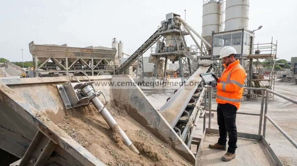
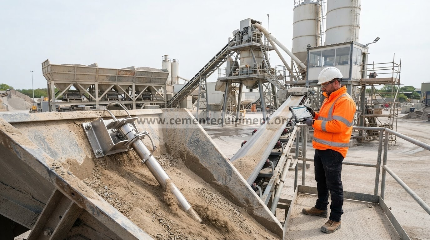
A blocked or restricted cement weigh-hopper vent path can make dosing slow, cause pressure or vacuum in the hopper, disturb load-cell readings and increase dust leakage. Diagnose the venting system before recalibrating the scale: record the weight trace, inspect the vent filter and hose, verify air can leave and enter the hopper freely, then confirm that flexible connections are not transmitting mechanical load to the weigh structure.
Restore stable cement weighing when the hopper fills or discharges slowly, pressure builds, dust escapes or the indicated mass becomes erratic.
Use the mass-versus-time trace, vent condition, filter restriction, flexible-hose condition, load-cell behavior, fill rate and discharge timing together.
Correct vent restriction and mechanical loading first; recalibrate only after the hopper breathes freely and the weighing structure is mechanically isolated.
Fast diagnostic order
- Trend cement mass, fill time and discharge time for several batches.
- Inspect the hopper vent filter, vent hose and dust-collector connection for restriction or collapse.
- Check whether pressure or vacuum changes coincide with unstable load-cell readings.
- Verify flexible sleeves and connected piping are not mechanically loading the weigh hopper.
- After correction, confirm repeatable batch mass and normal fill/discharge time before recalibration.
Capture the weighing pattern before opening the system
Record: target mass; actual mass; fill time; discharge time; load-cell signal stability; screw or pneumatic feed status; visible dust release; vent-filter differential pressure if available; pulse-cleaning status where fitted; hopper pressure indication if available; and whether the error appears during filling, settling or discharge.
A weighing error that begins only while cement is entering the hopper often points toward venting or mechanical-force effects rather than a static calibration problem.
1. Inspect the hopper vent path
The weigh hopper must displace air as cement enters and admit air as cement leaves. Check the vent filter, vent hose and any connection to the dust collector. Look for blinded filter media, collapsed hose, cement buildup, closed dampers or a blocked connection. A restricted vent can create internal pressure during filling and vacuum during discharge.
2. Compare vent condition with the weight trace
Watch whether the indicated mass becomes unstable only at high fill rate or immediately after the inlet closes. If the load-cell signal moves while no additional cement is entering, pressure relaxation or mechanical movement may be influencing the reading. Compare the same batch with the vent path restored.
3. Check flexible connections and pipe forces
The weigh hopper must remain mechanically isolated from fixed plant structures. Inspect flexible sleeves at the inlet and discharge, vent hose routing, cable trays and any attached air lines. A sleeve that is stretched, packed with cement or installed under side load can transfer force into the hopper and create false weight. Check the complete movement range, not only the empty position.
4. Inspect the vent filter cleaning system
Where the hopper uses a small pulse-cleaned filter, confirm compressed-air supply, pulse sequence, solenoids and hopper dust return. A filter can look clean externally while the media is blinded. Use the installed filter’s pressure-drop or maintenance criteria rather than inventing a universal limit.
5. Check the cement feed rate and cut-off behavior
Excessive feed rate can overwhelm a marginal vent path and increase in-flight material after the stop command. Compare the fault at coarse and fine feed. If the weighing system is stable at low feed but unstable at high feed, inspect vent capacity and material flow before tuning the controller.
6. Check discharge venting
During discharge, the hopper must admit replacement air. A blocked vent can create vacuum and slow material release, sometimes leaving residual cement that affects the next batch. Compare discharge time and residual mass before and after vent correction.
7. Recalibrate only after the mechanical system is stable
Once venting, flexible connections and feed/discharge behavior are proven stable, verify zero and span according to the weighing-system procedure. Calibration should confirm a mechanically sound system, not hide pressure or structural forces.
First-pass displaced-air sanity check
For a quick diagnostic comparison, convert the cement filling rate into an approximate solids volume rate: volumetric solids rate = mass rate ÷ measured bulk density. The hopper must at least accommodate the air displaced by that incoming solids volume, and the real venting load can be higher because aerated cement carries and releases additional air.
Example: if 600 kg enters in 30 seconds and the measured loose bulk density for that cement is 1,200 kg/m³, the solids volume is about 0.5 m³ per batch. Over 30 seconds, that corresponds to a baseline displacement rate of about 60 m³/h before allowing for entrained or conveying air. This is a diagnostic estimate, not a filter-sizing rule.
Use it comparatively: if dust leakage or weight instability appears only after the fill time is shortened, compare the old and new volumetric fill rates, then inspect filter restriction, vent path and pulse cleaning before assuming the load cells are wrong.
Weigh-hopper venting diagnostic matrix
| Observed pattern | Likely direction | Priority check |
|---|---|---|
| Weight signal drifts during fast filling | Vent restriction / pressure effect | Vent filter, hose, dust connection, fill rate |
| Mass changes after inlet closes | Pressure relaxation or flexible-joint force | Hopper breathing, sleeve tension, pipe contact |
| Discharge is slow and residual mass remains | Vacuum / poor air admission | Vent path during discharge, filter restriction |
| Zero changes after maintenance | Mechanical loading | Flexible sleeves, cable routing, fixed contact |
| Stable at low rate, unstable at high rate | Vent capacity or high in-flight material | Filter condition, vent size/path, feed transition |
Common mistakes
- Recalibrating the load cells before checking the vent path.
- Ignoring flexible sleeves that are stretched or packed with cement.
- Assuming a clean filter exterior means the media is not blinded.
- Increasing feed rate without checking whether displaced air can escape.
- Diagnosing discharge delay only as a material-flow problem while the hopper is pulling vacuum.
Return-to-service acceptance checklist
- The vent path remains open through filling and discharge.
- Flexible connections remain free and do not transmit visible mechanical load.
- The mass trace is stable after feed cut-off.
- Fill and discharge times are repeatable across consecutive batches.
- Actual cement mass remains within the plant’s approved weighing tolerance.
- Zero remains stable after a complete fill/discharge cycle.
- Final vent, filter and weighing observations are recorded as the new baseline.
Frequently asked troubleshooting questions
Can a blocked vent filter create a false weight reading?
Yes. Pressure or vacuum inside the weigh hopper can interact with flexible connections and the structure, producing a changing load-cell signal even when cement mass is no longer changing.
Why does the weight drift after the inlet valve closes?
Check pressure equalization, flexible-joint forces and in-flight material. If the signal settles as the hopper pressure relaxes, venting deserves close inspection.
Should the load cells be recalibrated first?
No. Prove that the hopper breathes freely and is mechanically isolated before calibration. Otherwise calibration may mask the real fault.
Related Infinity technical guides
Engineering reference basis
Use the installed batching-plant, weigh-hopper, vent-filter and load-cell OEM manuals for final filter limits, calibration tolerances, fill rates and maintenance procedures. The sequence above is intended to separate venting, mechanical and weighing causes before adjustment.