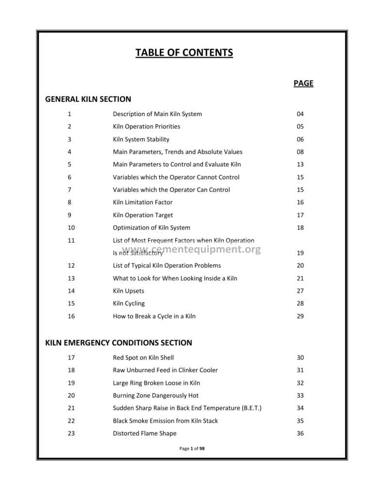
Kiln Combustion Cooler Course: Complete Guide
The kiln combustion and cooler course is the training pack of the burning line: the combustion of the flame in the rotary kiln, the aerodynamics of the burner, the heat recovery of the clinker cooler: the two systems that decide the fuel bill of the plant: when the kiln operators walk the morning round, they check the flame first and the cooler second: the flame gives the clinker quality, the cooler gives back the heat: this course covers the whole pair in one file: the burner, the flame, the combustion chemistry, the cooler grate, the fans and the recuperation methods.
The Complete Cement Technical Package (931 files including this course, the handbooks, the Excel tools and the presentations: $249.99 one-time: instant download via the PayPal payment) hosts this course with its diagrams, its tables and its worked examples: this article walks the file: the theory of the combustion, the practical burner settings, the cooler operation and the troubleshooting pages: the reader finishes with the numbers to run a modern burning line of 5,000 tons per day with confidence: the flame in one hand, the cooler balance in the other.
The burning line is a chain of linked machines: the preheater removes the CO2, the kiln sinters the clinker, the cooler quenches and recovers: each stage modifies the state of the next: the combustion quality sets the kiln temperature profile, the kiln discharge temperature sets the cooler job, the cooler secondary air closes the loop back to the burner: this is why the course treats the burner and the cooler as one system: the article follows the same logic, section by section, with the same numbers the plant uses every day.
1. The Anatomy of the Kiln Combustion System: From Fuel to Flame
The combustion system of the rotary kiln comprises five functional blocks, and the course draws each one before it teaches the operation:
- The fuel line: the coal mill, the silo, the feed screw, the conveying air or the pulverized fuel injection: for the coal-fired kilns, the coal is ground to 3 to 5% residue on 90 micrometers and dried to below 2% moisture before the burner sees it;
- The burner pipe: the tube that carries the fuel to the kiln nose, with the swirl blocks, the central channel and the annular ducts for the primary air: the geometric heart of the flame;
- The primary air fan: the 8 to 12% of the total combustion air delivered through the burner at 60 to 120 m/s, carrying the fuel and shaping the flame;
- The secondary air: the hot air from the cooler at 700 to 900 °C in the modern grate cooler systems, drawn into the kiln by the draught of the system;
- The tertiary air duct: in the precalciner kilns, the separate duct that takes the hot cooler air directly to the calciner vessel, bypassing the kiln, to fire the calciner fuel;
The five blocks work as one breathing system: the fuel enters with the primary air, the secondary air arrives through the kiln hood, the tertiary air splits off at the cooler: the total draught is set by the kiln induced draught fan (ID fan) and the balance of the pressures is the daily game of the operator: the course teaches the pressure map of the system because most combustion problems are, at the root, pressure problems.
2. The Combustion Chemistry: The Stoichiometry of the Kiln Flame
Combustion in the kiln is the oxidation of the fuel carbon and hydrogen: the course reviews the stoichiometry because the operator who understands the air numbers reads the gas analyzer like a book:
C + O2 = CO2 (the carbon burn: 1 kg of carbon needs 2.66 kg of oxygen and releases about 32.8 MJ) and 2H2 + O2 = 2H2O (the hydrogen burn: 1 kg of hydrogen needs 8 kg of oxygen and releases about 120 MJ) and S + O2 = SO2 (the sulfur burn, the minor partner that the kiln systems must not forget).
The theoretical air requirement of the typical bituminous coal with 70% carbon, 4% hydrogen and 12% ash is about 7.5 to 8.2 Nm³ of air per kg of coal: the plant then adds the excess: the kiln operates at 2 to 3% oxygen at the kiln inlet gas sample point, which corresponds to about 10 to 15% excess air: the oxygen at the rotary kiln inlet is the prime control variable of the burning:
- O2 below 1.5%: the risk of the reducing atmosphere, the ring formation, the sulfates, the dark clinker: the fuel economy paid in trouble;
- O2 between 2 and 3%: the normal window for the stable complete combustion with the acceptable NOx;
- O2 above 4%: the wasted heat in the flue gas: every 1% of excess oxygen costs roughly 0.8 to 1.2% of the thermal energy of the system: the money literally up the stack;
The calculation example of the course: a 5,000 ton per day kiln firing 12 tons per hour of coal: the theoretical air is 12,000 kg/h × 8.0 Nm³/kg ≈ 96,000 Nm³/h: with the 12% excess air, the actual is near 108,000 Nm³/h: the main fan, the preheater and the ducts are all sized for this flow: the numbers of the sizing start here.
3. The Flame: The Shape, the Length and the Temperature of the Burning Zone
The flame of the kiln is a jet flame anchored at the burner tip, and its shape decides the clinker: the course trains the eye on four flame properties:
- Length: the good clinker flame is 10 to 15 times the diameter of the burner pipe, ideally covering the burning zone without washing the kiln inlet: a flame too short concentrates the heat, a flame too long pushes the coating problems toward the preheater;
- Shape: the slightly divergent, bushy flame with the solid bright core: the axial and radial momentum of the primary air controls the divergence: the swirl registers of the burner are the shaping tools;
- Temperature: the theoretical adiabatic flame temperature of the coal fired with the preheated air reaches 2000 to 2200 °C: the practice sees 1650 to 1850 °C in the flame core and 1450 to 1550 °C as the clinker burning temperature;
- Position: the flame axis running slightly below the kiln axis, hitting the bed at the end of the burning zone: the luminous zone ends where the coating starts to glow evenly;
The operator reads the flame through the kiln camera infrared system and the optical pyrometer: the course teaches the standard checks: the flame must be bright without the dark tail, the flame root must stay 300 to 600 mm off the nose ring, and the fuel must ignite within one or two burner diameters, otherwise the LCV (low calorific value) fuels or the wet coal are to blame.
4. The Fuels of the Kiln: Coal, Petcoke, Gas, Oil and the Alternative Fuels
The burning line accepts a portfolio of fuels and the course dedicates a full chapter to the fuel switch because the fuel is most of the variable cost:
| Fuel | Typical LCV (MJ/kg) | Volatiles % | Notes for the burner |
|---|---|---|---|
| Bituminous coal | 27 – 32 | 25 – 40 | The reference fuel: stable flame, 3 – 5% R90 residue |
| Petroleum coke | 33 – 35 | 8 – 12 | Hard to ignite: needs 4 – 8% extra primary air and higher flame temperature |
| Natural gas | ~48 | n/a | Fast ignition: shorter flame, higher NOx without care |
| Heavy fuel oil | 40 – 42 | n/a | Atomization at 3 – 5 bar steam or air: temperature of the oil 100 – 140 °C |
| RDF / tires / SRF | 14 – 26 | high | Cofiring 10 – 60%: needs the calciner injection route and the pollutant control |
The petcoke switch is the classic modernization case the course walks through: petcoke ignites late, so the operator raises the primary air by one or two percent, tightens the swirl to stabilize the root, and raises the kiln inlet temperature target by 10 to 20 °C: the precalciner takes over the extra volatile-unrelated load: the result is the fuel bill down by 5 to 10% versus coal at the equal calorific value: the numbers of the switch are all in the tables of the file.
5. The Burner Design: The Pipe, the Swirl and the Primary Air Registers
The modern kiln burner (the multifuel channel burner from FLS, KHD, Pillard or the Chinese equivalent) is a compact nozzle with several concentric ducts: the course dissects the geometry register by register:
- The central duct: the carrier air that transports the pulverized fuel, 2 to 4% of the total combustion air, velocity 25 to 35 m/s: the fuel exits through the 20 to 50 mm central nozzle;
- The swirl air duct: the annular channel around the fuel, with the tangential slots or the spiral registers: 5 to 7% of the air at 90 to 140 m/s: the rotating air generates the recirculation that stabilizes the ignition;
- The axial duct: the straight jets at 100 to 200 m/s that punch the flame forward: the balance of the swirl vs the axial momentum sets the flame length;
- The outer sleeve (the conveying duct): in the newest designs, the annular cooling air or the tertiary-like quenching air that protects the burner tip from the 1800 °C radiation;
- The flame shaping rules: more swirl means the shorter, fatter, hotter flame: more axial means the longer, narrower flame: the operator tunes the ratio for the coating, the clinker and the NOx;
The practical setting of the course: for the standard coal flame, start with the swirl ratio at 40 to 60% of the register opening, the axial at full, and adjust the flame root anchoring by closing the registers in 5% steps until the camera shows the stable root without the lift-off: every 10% of swirl increase shortens the flame by roughly one kiln diameter: the tuning table of the file gives the full set of directions.
6. The Combustion Control Loop: Oxygen, CO and the Nitrogen Oxides
Modern kilns control the combustion with the continuous gas analysis and the course is explicit about the control hierarchy:
- O2 at the kiln inlet: the lagging master: the 2 to 3% window: the draught of the main fan is trimmed in 1 to 2% steps with the 10 to 20 minute lags respected;
- CO at the preheater exit or the riser: the fast acting safety limiting value: the CO above 0.3 to 0.5% triggers the cutback of the kiln fuel feed or the rise of the draught: the explosive limit discipline of the bag filter feeds on the CO reading;
- NOx: the 400 to 900 mg/Nm³ typical for the coal kilns: the flame temperature and the excess air are its masters: the SNCR urea injection cuts it 30 to 60% when the limit bites;
- The temperature pairing: the kiln inlet gas temperature 950 to 1100 °C and the kiln shell scanning for the hot spots of the burning zone: the combination tells the real burning state better than any single probe;
The classic control incident the course analyzes: the O2 at 3.5% and the fuel rate is raised to keep the temperature: the flame lengthens, the coating spalls, the kiln inlet temperature jumps: the lesson: the combustion control is the search of the minimum workable O2, not the maximum temperature: the best kilns run the O2 at 2.2 to 2.6% and let the burning zone do the work.
7. The Clinker Cooler Mission: Quench, Recover and Return the Air
The cooler of the modern line is the reciprocating grate cooler, and the course dedicates its second half to the machine that the operators affectionately call “the money savers of the plant”:
- The quenching: the clinker enters at 1300 to 1450 °C and must fall below 100 °C within a few minutes: the fast cooling freezes the alite structure for the strength: the glassy alite of the slow cooling loses up to 30% of the 28-day strength in the extreme cases;
- The heat recovery: the air blown through the grate picks the heat of the clinker: the grate recuperates 65 to 75% of the clinker heat in the modern three-zone coolers with the static pre-grate:
- The secondary air return: 20 to 35% of the cooler air returns to the kiln at 750 to 900 °C, the fuel saver: each 100 °C of higher secondary air temperature saves 1.5 to 2% of the specific heat consumption;
- The tertiary air return: 25 to 35% of the cooler air goes through the tertiary duct to the calciner at 750 to 900 °C: in the precalciner kilns this is the second fuel saver;
- The vent air: the remaining 30 to 50% is drawn by the cooler vent fan through the bag filter: this is the “waste” that the modern plants recover in the waste heat recovery boiler or the kiln raw mill dryer;
The cooler balance in numbers: the 5,000 ton per day line has a grate area of 120 to 150 m², a grate speed in the 15 to 25 strokes per minute at the rated load, a cooling air flow of 1.8 to 2.2 Nm³ per kg of clinker and a clinker exit temperature of 80 to 110 °C plus the ambient: the course teaches to read the cooler as a heat exchanger before a conveyor: the airflow split is the real control knob.
8. The Grate Cooler Mechanics: The Bed, the Plates and the Fans
The grate cooler moves the clinker on the rows of the moving plates with the air chamber below, and the course covers the mechanical heart:
- The grate plates: the alloy steel castings with the small holes or slots: the typical plate life is 8 to 18 months at the 1300 °C end, longer toward the middle: the plate gap and the wear monitoring are the maintenance program;
- The drive: the hydraulic cylinders or the crank drives push the rows in the 10 to 30 millimeters stroke at 5 to 30 strokes per minute: the stroke is the bed speed control;
- The air compartments: 6 to 12 under-grate chambers, each with its own fan and its damper: the under-grate pressure reads 3 to 8 kPa, the first compartment the highest;
- The fans: the centrifugal fans sized at 1.8 to 2.2 Nm³/kg clinker total: the first compartment fans deliver the high pressure for the hot clinker bed, the later ones lower pressure and more flow;
- The clinker crusher: the rolling crusher at the cooler end crushes the bed: the breaker opens 30 to 40 mm: the final clinker leaves at 30% below 25 mm for the mill feed convenience;
The operating discipline of the cooler: the bed must stay at 60 to 80 cm deep in the first zones, the pressure drop across the bed is the bed thickness indicator, and the operator balances the grate speed against the kiln production: the hydraulic pressure of the drive is the direct load gauge: the course trains the reading of the cooler dashboard: six pressures, six fan dampers, one speed, one product temperature.
9. The Cooler Heat Balance: The Recuperation Numbers of the 5,000 tpd Line
The course works a full cooler heat balance as the capstone exercise, and the numbers are the ones the plant audits every year:
Input: the clinker at 1350 °C with the specific heat of 0.83 kJ/kg·K carries about 1,120 kJ per kg (the sensible heat of the clinker). Outputs: the secondary air carries back 400 to 450 kJ/kg, the tertiary 350 to 400 kJ/kg, the vent air 150 to 220 kJ/kg, the radiation and the losses 50 to 80 kJ/kg, and the clinker leaves with 80 to 120 kJ/kg. The split of the airflow (2 Nm³/kg at 2.0 is the 36% secondary, 32% tertiary, 32% vent) follows from the target recuperation of 700 to 850 kJ/kg into the two hot air streams.
- Recuperation factor: secondary + tertiary heat divided by the clinker sensible heat: the modern coolers reach 0.70 to 0.78, the old planetary coolers only 0.45 to 0.55: the difference is worth 1.5 to 2.5% of the kiln fuel;
- The specific heat consumption: the line at 3,100 to 3,300 kJ/kg clinker for the best preheater kilns, of which the cooler losses are 40 to 70 kJ/kg: every 10 kJ/kg is a 0.3% entry on the fuel bill;
- The audit method: measure the clinker temperature entering and leaving, the air flows and temperatures, the vent filter load: the balance closes within 5% when the measurements are honest;
The lesson of the balance: the cooler is the heat exchanger with the flue gas in reverse: the cold air leaves hot, the hot clinker leaves cold: the plant that masters the split has already saved the megawatts before the flame is even lit.
10. The Operation of the Cooler: The Bed, the Red River and the Clinker Ball Troubles
The cooler operators live with four classic problems and the course gives the playbook for each:
- The red river: the channel of the burning clinker in the middle of the grate where the bed opens up, the under-grate temperature spikes over 250 °C and the plates overheat: the countermeasures: close the under-grate damper of the hot zone, slow the grate, raise the airflow of the adjacent compartment, and call the kiln side to reduce the flame temperature;
- Snowmen / the clinker balls: the agglomerated lumps up to 500 mm that block the crusher: they come from the sticky kiln coating, the alkali salt enrichment or the too high firing: the cure is preventive: the stable kiln, the controlled alkalis, the ratio of the sulfur to the alkalis kept below 1 in the molar terms;
- The clinker fall-through: the fine clinker sifting through the plate gaps raises the temperature of the first compartment air: the remedy is the fine-grain plate sealing and the proper bed: the compartment sand collects under the grate;
- The hot clinker out: the exit temperature over 120 °C means the under-cooling: the quick check is the increased grate speed, the pressure drop falls, the later zone dampers open: the long term fix is the airflow audit of the cool zone fans;
The trouble table of the course links each symptom to the cause list and the first action: the red river to the damper; the snowmen to the kiln; the fall-through to the bed; the hot exit to the speed: the operators rehearse the table until the reaction is reflex.
11. The Link of the Kiln and the Cooler: The Secondary Air Temperature Discipline
The recuperation chain closes on the burner: the secondary air temperature is both the cause and the effect of the whole line, and the course is emphatic about the discipline:
- The target: the secondary air at 800 ± 50 °C measured at the kiln hood, and the tertiary at 780 ± 50 °C: the deviations beyond ±100 °C immediately cost or gain 1.5 to 3% of the fuel;
- The causes of a low value: the thin bed, the high grate speed, the open vent damper pulling too much cold air, the false air leaks at the hood and the kiln inlet seal;
- The causes of a high value (with the hot clinker): the under-cooling: the air takes the heat but the clinker leaves hot: the balance sheet unchanged but the cement quality suffers in the mill;
- The measurements: the thermocouples in the hood and the tertiary duct, checked against the kiln camera brightness and the color of the flame: the recovery of the confidence happens when the two agree;
The one-page summary of the course: the operator manages the hot air split with three dampers (the tertiary damper, the vent damper, the hood damper) and one speed (the grate): the training board of the plant reproduces the cooler mimic and the trainee balances the four controls until the secondary air sits on the target line.
12. The Course Method: The Tables, the Exercises and the Case Files of the Training Pack
The file is a teaching pack and the course structure is worth describing, because the learner uses it the way the course intends:
- The theory chapters: the combustion chemistry, the flame physics and the heat balance with the step-by-step derivations: each chapter ends with the self-test of 10 questions;
- The operation chapters: the standard operating procedures of the burner start-up, the flame tuning, the cooler ramping and the emergency stops, written as the checklists;
- The case files: the annotated incidents from the plants: the petcoke switch, the red river recovery, the NOx compliance campaign: each case with the data table and the lesson box;
- The Excel companions: the combustion air calculator, the cooler balance sheet and the flame parameter log: the trainees enter their own numbers and see the line move;
- The examination: the final 40-question paper with the marking scheme: the plants that use the pack for the operator certification adapt it to their own SOPs;
The course closes with the operator proficiency matrix: each skill from the flame reading to the cooler damper tuning is graded 1 to 5, and the plant pins the matrix on the control room wall as the training map of the burning line team.
13. The Start-Up, the Shutdown and the Emergency Stops of the Burning Line
The combustion system is easy to operate in the steady state and unforgiving in the transitions: the course devotes its operation chapters to the sequences, because most of the incidents of the burning line happen during the starts, the stops and the trips:
The start-up sequence of the coal-fired line: the preheater and the kiln are purged with the main fan at 30 to 50% for at least 5 to 10 minutes to clear the combustible gases; the light-up burner (the diesel or the gas lance) ignites with the flame scanner proving the flame; the kiln is warmed at the ramp of 50 to 80 °C per hour of the shell temperature, with the kiln on the inching drive until the shell reaches the 150 to 200 °C; the coal feed starts only when the kiln hood temperature exceeds 800 °C and the flame scanner confirms the stable ignition; for the first 2 to 4 hours the kiln runs at 50 to 60% of the rated fuel, building the coating before the load ramps.
- The purge rule: never admit the fuel without the purge: 5 full volume changes of the system air: the rule is non-negotiable and written into the interlock logic of the control system;
- The flame scanner: the ultraviolet or the infrared scanner on the burner: the fuel valves close automatically if the flame is lost for more than 3 to 5 seconds: the trip saves the explosion, the nuisance trips cost hours: the scanner lens cleaning is a daily routine task;
- The cold start watch: the condensate and the moisture in the ducts, the ice in the coal line, the thermal shock of the grate: the operators run the start at the reduced draught and rise the oxygen target to 3.5 to 4% during the ramp;
The normal shutdown: the fuel is cut first, the kiln turns on the inching drive for 8 to 24 hours to cool without the sag, the cooler keeps running until the clinker bed empties, and the vent bag filter stays on to catch the dust: the emergency stops (the fan trip, the power loss) flip the kiln to the auxiliary drive, fire the standby generators for the cooler hydraulics and the fan dampers, and log the shell temperatures every 30 minutes: the course gives the full trip matrix, because the trip response is the difference between the nuisance stop and the kiln disaster.
14. The Key Performance Indicators of the Burning Line: The Dashboard of the Course
The course ends the technical chapters with the KPI list, the numbers the plants benchmark against the industry best practice (the 3,100 to 3,350 kJ/kg clinker band for the modern precalciner lines):
| KPI | Typical value | Unit | Good operating practice |
|---|---|---|---|
| Specific heat consumption | 3,100 – 3,350 | kJ/kg clinker | monthly audit by heat balance |
| Kiln inlet O2 | 2.0 – 3.0 | % | hold 2.2 – 2.6% band |
| Secondary air temperature | 750 – 900 | °C | ±50 °C on target |
| Tertiary air temperature | 730 – 880 | °C | within 50 °C of secondary |
| Clinker exit temperature | 80 – 120 | °C | under 100 °C at the grate end |
| Cooler air ratio | 1.8 – 2.2 | Nm³/kg clinker | flow audit each quarter |
| NOx at the stack | 400 – 900 | mg/Nm³ | according to the permit |
| Kiln availability | 90 – 95 | % | the unscheduled stops under 10 |
| Free lime in clinker | 0.8 – 2.0 | % | sampled every 2 hours |
| Coating stability | stable zone | n/a | shell scanning trend flat |
The dashboard discipline: the KPIs are plotted as the trends, not the snapshots: the plant reviews the weekly averages against the monthly targets, and the deviations of more than one band width trigger the investigation with the data of the control system historian: the operators who run the burning line with this dashboard find the drift of the system weeks before the clinker quality pays for it: the course pages the whole set of the benchmarks and the alarm limits in the appendix tables.
15. The Coating, the Rings and the Burning Zone Management
The combustion course would be incomplete without the coating chapter, because the coating is the flame’s footprint on the refractory and the ring formation is the flame’s failure mode:
The coating: the 50 to 250 mm layer of the clinker melt that protects the magnesia-spinel bricks of the burning zone: the coating forms when the liquid phase of the burning clinker (25 to 30% liquid at 1450 °C for the normal raw mix) wets the hot brick and freezes: the coating is the shield: the good coating extends the refractory life from 8 to 12 months to 18 to 30 months and stabilizes the kiln heat balance:
- The coating indicators: the shell temperature at 260 to 330 °C over the burning zone measured by the scanner ring: the coating thickness of 100 to 200 mm shows as the smooth stable shell band: the sudden hot spots over 380 °C mean the lost coating and the imminent brick damage;
- The coating control: the flame position and the burning zone temperature are the levers: the flame too high on the brick line burns the coating away, the flame too low floods the bed: the operator centers the flame 50 to 100 mm below the kiln axis and keeps the free lime of the clinker in the 0.8 to 2.0% band as the coating proxy;
- The spring and the fall: the coating cycles with the feed composition: the sudden rise of the liquid phase (the alkali or the sulfur spikes in the raw mix) builds the coating fast and then spills it; the plant watches the raw mix modules and the alkali balance to keep the coating cycle gentle;
The ring formation: the annular build-ups in the burning zone and the nose ring that choke the kiln: the reducing atmosphere (the O2 under 1.5%) reduces the sulfur to the sulfides that cement the dust into the hard ring; the alkali-sulfur cycles feed the build-up; the dense ring at the end of the burning zone raises the material level, drives the clinker over the ring in the avalanche, and the kiln complains with the fluctuating torque:
- The early signs: the rising kiln drive amperage, the falling kiln inlet temperature at the constant fuel, the shell thermocouple pattern of the localized hot ring;
- The cure: the preventive discipline: the O2 at 2.5% plus, the stable feed composition, the alkali-to-sulfur molar ratio managed below 1: the emergency cure: the reduced kiln speed and the higher O2 with the lower fuel for 2 to 4 hours to burn the ring down, the kiln shooting with the stabilized flame and, in the stubborn cases, the targeted shutdown of the kiln to knock the ring off;
- The nose ring: the build-up at the discharge end from the dust and the melt: the operator holds the nose ring temperature in the 1050 to 1150 °C band and watches the flame root distance to keep the nose ring clear;
The course teaches the coating as the live organ of the kiln: the shell scanner is its thermometer, the free lime is its blood test, and the flame is its heart: the burning zone management is the craft of the kiln operator, and the file puts the full playbook with the trend charts into the hands of the trainee: the ring log, the coating history, the scanner map: the complete clinical record of the burning zone.
16. Frequently Asked Questions
What is the correct oxygen at the rotary kiln inlet?
The standard operating window is 2 to 3% O2 at the kiln inlet sample point: below 1.5% the reducing atmosphere risks the rings and the sulfate problems; above 4% the excess air wastes 0.8 to 1.2% of the thermal energy per each extra percent: the best operators hold a tight 2.2 to 2.6% band and use the CO as the tripwire.
Why is the secondary air temperature so important?
Each 100 °C of the secondary air temperature represents about 1.5 to 2% of the kiln fuel consumption: the hot air also raises the flame temperature and stabilizes the burning zone: the recuperation ratio of the cooler is measured precisely on this temperature, and the plant audits it monthly.
Can the petcoke be fired without the modification of the burner?
With difficulty: the petcoke needs 8 to 12% volatiles, and the late ignition demands the higher primary air ratio and the stronger swirl: the burner with the adjustable registers can usually cope with the blending up to 30 to 50% petcoke, above that the dedicated petcoke burner geometry is recommended: the course gives the blending table for the smooth transition.
What is a good cooler recuperation factor?
The modern grate coolers reach 0.70 to 0.78 (the ratio of the recovered secondary plus tertiary heat to the clinker sensible heat): the old planetary coolers sit at 0.45 to 0.55: the difference is worth up to 2.5% of the kiln fuel: the cooler modernization is the classic payback project of the energy audits.
How often should the cooler be inspected?
The daily visual round checks the grate movement, the pressures and the temperatures: the weekly thermal camera round maps the hot plates: the full internal inspection with the plate measurement and the crusher check is scheduled with the kiln major shutdown, typically every 6 to 12 months: the course includes the inspection checklist with the wear limits of the plates and the air seals.
Does the course include the precalciner combustion?
Yes: the precalciner vessel is the combustion system in miniature: the course covers its fuel mix, the tertiary air damper control, the 85 to 95% calcination degree target and the CO/NOx balance of the vessel: the operator of the modern line controls the calciner temperature 840 to 880 °C as the first handle of the burning line.
17. Conclusion
The kiln combustion and cooler course is the operator’s manual of the burning line economy: the flame is the master, the cooler is the recycling heart: the course ties the two with the numbers the plant can audit: the oxygen window, the flame tuning, the air split and the recuperation balance: the reader who works through the file finishes with the complete control picture of the modern burning line, from the coal hopper to the clinker silo.
The Complete Cement Technical Package includes this course with its diagrams, its tables and its Excel tools: the one-time $249.99: the instant download: the 931 files of the cement library: the burning line knowledge of the professionals, collected and organized: the flame of the kiln, the heat of the cooler, in one package: the engineering career, powered.
Get this kiln combustion & cooler course file + the full 931-file package
$249.99 — one-time purchase, instant download, lifetime access
This file is part of the Complete Cement Technical Package (931 files) available from cementequipment.org. Respective rights holders; library copy for the licensed single user.