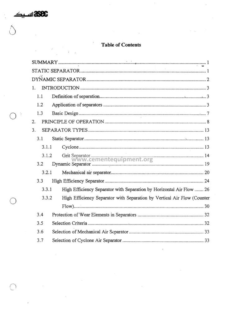
Air Separator in Cement Mill: Complete Guide
The air separator is the classification machine of a closed grinding circuit. It splits the mill discharge into a fine product stream and a coarse reject stream that returns for further grinding. Its performance influences product fineness, particle-size distribution, circulating load and specific energy, but those outcomes depend on the complete mill–separator circuit rather than the separator alone.
The Complete Cement Technical Package includes 931 cement-industry files covering books, courses, Excel tools and presentations. The $249 one-time package includes this air-separator guide with classification theory, Tromp-curve material, separator types and operating references, with instant download access immediately after payment.
Separator performance can materially affect circuit throughput, specific energy and product PSD, but there is no fixed conversion from one bypass point to a percentage of mill output. The economic impact should be quantified from the plant’s measured throughput, complete-circuit kWh/t and product-quality data.
1. The Principle of the Air Classification: The Forces on the Particle
The air separator works by the balance of the forces on the particles in the air stream, and the file opens with the physics of the classification:
- The forces: the drag force of the air (proportional to the particle surface and the air velocity) and the centrifugal force of the rotating flow (proportional to the particle mass and the rotor speed): the fine particles follow the air to the fines outlet: the coarse particles escape the drag and fall to the rejects: the equilibrium particle size is the cut size of the separator;
- The cut size: d50 is the particle size at which the stated Tromp-curve probability equals 50%. Its value depends on separator geometry, airflow, rotor speed, feed loading, feed PSD and the product target, so it should not be treated as one universal cement range.
- The classification of the mixture: the feed of the mill discharge contains the wide size range: the separator must split at the desired cut with the minimum of the misplaced particles: the perfect classifier would give the sharp step function at the cut: the real machines give the S-curves of the Tromp:
- The air circuit: classifying air moves fines through the separator and into the product-collection system. Required airflow and fan duty depend on separator size, solids loading, pressure drop and circuit layout; use measured flow/pressure and OEM design data rather than one generic m³/h range.
The physics section of the file sets the language of the craft: the cut size, the fines, the rejects, the bypass: the operators and the engineers of the package speak the same words from the first chapter: the classification forces, made visible by the numbers of the file.
2. The Generations of the Separators: From the Static to the Dynamic
The history of the air separator is the history of the improvement of this force balance: the file reviews the machine generations:
| Generation | Type | Typical classification character | Best comparison basis |
|---|---|---|---|
| Early static | Static / gravity-assisted classifier | Limited cut control and broader separation | Compare with the unit’s own clean baseline and product duty |
| Mechanical dynamic | Whizzer / rotating-blade designs | Adjustable cut with moderate selectivity | Compare Tromp curve, airflow, loading and product quality |
| Modern dynamic | Cage-rotor high-efficiency designs | Higher potential selectivity and improved dispersion | Compare against OEM design and verified plant performance |
Separator designs evolved from simple static classifiers to mechanical dynamic machines and modern cage-rotor separators with improved feed dispersion and aerodynamic control. Retrofit value should be determined from the measured condition of the existing separator and a supplier-backed post-upgrade guarantee, not from a generic capacity percentage assigned to separator generation.
3. The High-Efficiency Separator: The Construction of the Modern Machine
The modern high-efficiency separator (the third generation) is the standard of the current plants, and the file details its construction:
- The feed and the dispersion: the mill discharge enters the top and falls onto the distribution plate: the dispersing air and the rotating elements spread the material into the classifying zone: the good dispersion is the prerequisite of the sharp cut: the undispersed lumps pass the classifier as the misplaced rejects;
- The cage rotor: the rotating cage forms the dynamic classification zone. Rotor speed and tip velocity depend on separator diameter, blade geometry and OEM design. Rotor speed is a major fineness-control variable, but use the machine’s actual operating range rather than a generic rpm or tip-speed value.
- The guide vanes: the adjustable stator vanes create the tangential air entry: the guide vane angle and the rotor speed together set the cut: the modern machines adjust the vanes during the operation: the online fineness control of the finish mills;
- The rejects cone and the fines outlet: the coarse material falls to the inner cone and returns to the mill: the fines leave with the air to the collecting cyclone or the filter: the internal air circulation eliminates the external fan ducting: the closed-circuit buffer of the machine;
- The drive and the control: the VFD rotor drive with the fineness setpoint loops: the new machines integrate the separator control with the mill’s expert system: the automatic response to the Blaine targets: the modern classification, an instrumented process unit.
The construction chapter of the file includes the section drawings and the specification tables (the rotor diameters of 1 to 4 meters, the capacities of 20 to 250 t/h, the air flows per the fan curves): the engineer who reads the construction chapter reads the supplier proposals critically: the machine internals, understood completely.
4. The Tromp Curve: The Signature of the Classifier
The classification performance is measured by the Tromp (or the partition) curve, and the file teaches the instrument completely:
- The construction of the curve: analyze separator feed, fines and rejects with the same particle-size method, then calculate the partition probability for each size class using a stated curve convention. Judge mass-balance closure against the uncertainty of the sampling, flow measurement and laboratory method rather than a universal 1–2% rule.
- The cut size (d50): the particle size at 50% partition probability under the stated convention. Interpret d50 together with separator-feed PSD, bypass, sharpness and product specification rather than one generic cement range.
- The sharpness: one common imperfection definition is I = (d75 − d25) / (2 × d50). Other sharpness coefficients also exist, so the formula and curve convention must be stated before values are compared. Use the OEM/design or clean-machine baseline rather than universal numeric ranges.
- The bypass: under a reject-probability convention, bypass is inferred from non-ideal fine material reporting to rejects. Its numerical value depends on curve convention, particle-size resolution and operating duty, so it should be compared with a consistent clean/design baseline rather than a universal good-machine range.
- The fish-hook effect: the fines-coarse interactions that give the curve its upward bend at the very fine end: the agglomeration of the fines and their rejection: the modern analyses account for the effect: the file’s calculation sheet plots the curve from the three sievings and reads the parameters automatically.
The Tromp section is the analytical core of the file: the Excel tool builds the curve from the residue data of any shift: the file’s worked example (a 4.2 x 13.5 m finish mill with the 220 t/h of the separator feed, the 85 t/h product, the rejects 135 t/h: the bypass 9%, the d50 34 microns, the I 0.32) shows the complete audit: the separator performance, measured like the professionals measure it.
5. The Circulating Load: The Loop Between the Mill and the Separator
The closed circuit is defined by its circulating load, and the file quantifies the loop:
- The definition and calculation: at steady state, circulating load is commonly expressed as reject flow divided by fresh feed (which equals net product). When the same sieve or size cut is used for separator feed, product and rejects, CL can be estimated from the stream fractions as CL = (a − b) / (c − a), where a, b and c are the selected size fractions in separator feed, product and rejects. Use measured stream data and state the basis clearly.
- The circuit geometry: the mill discharge to the separator, the fines to the silo or the next classifier stage, the rejects back to the mill inlet: the fresh feed joins the rejects at the mill entry: the mill operates on the total feed (the fresh plus the rejects): the 300% circulating load means the mill grinds 4 tons for each ton of product;
- The optimum: very low or very high recycle can both indicate poor circuit balance, but there is no universal optimum percentage. The best operating point is the one that meets product specification with stable throughput and minimum practical complete-circuit energy for that mill and separator.
- The fineness split: trend separator-feed, product and reject PSD or sieve residues together. The difference between feed and product fineness is circuit-specific and should be measured rather than assumed from a fixed Blaine offset.
- The control of the loop: the separator speed and the mill feed: the expert systems hold the circulating load and the fineness simultaneously: the load feedback of the bucket elevator amps and the differential pressure of the mill: the loops of the modern DCS, documented in the file.
The circulating-load chapter connects the separator to the mill as the single grinding system: the engineers of the package never discuss the separator alone: the mill, the separator and the load, one system: the file’s balance sheets and the control diagrams give the complete system view: the loop, understood and controlled.
6. The Separator in the Finish Grinding: The Cement Fineness Control
The finish mill classification is the most quality-sensitive application of the air separator, and the file treats it with its full importance:
- The fineness targets: use the approved cement specification and the plant’s strength, setting and performance requirements to define Blaine, sieve residue and PSD targets. Do not apply one generic fineness window across different cement types or markets.
- The particle-size distribution: PSD affects hydration, packing and water demand, but there is no single ideal distribution for every clinker and cement formulation. Separator tuning should therefore be evaluated together with strength, setting, water demand and other required quality tests.
- The strength consequences: different particle-size fractions contribute differently to early and later hydration, but the optimum distribution is cement-specific. Do not use a universal percentage window as a strength guarantee; confirm separator changes with laboratory strength and performance testing.
- The sulfate and temperature balance: grinding temperature can influence calcium-sulfate dehydration and cement setting behavior. The acceptable limit depends on sulfate form, moisture, residence time and product quality, so use plant-specific validated temperature limits and approved cooling/water-injection procedures rather than one universal outlet temperature.
- The quality automation: online fineness or PSD analyzers can support separator control, but achievable control precision depends on sampling representativity, analyzer accuracy, process dead time and the control strategy. Validate online measurements against the laboratory before using them for automatic control.
The finish-grinding chapter of the file teaches the bit of the classification in the cement specification: the separation quality is not only an energy matter but the product-quality matter: the file’s distribution analyses and the strength correlations give the laboratory and the process the common language: the cement fineness, engineered by the classifier.
7. The Separators of the Raw Meal and the Coal Grinding
The air separator serves the other mill systems of the plant, and the file dedicates the section to each:
- The raw-meal classification: raw-mill fineness targets should be set from raw-material burnability, kiln requirements and plant quality control. Use the site’s validated R90/R200 or PSD targets rather than applying one universal residue range.
- The vertical roller mill classifiers: the integrated cage rotor at the top of the VRM: the classification inside the mill body: the raw meal fineness controlled by the rotor speed and the air flow: the VRM classifier is the same physics in the compact machine: the separate separator disappeared inside the mill;
- The coal-mill classification: coal fineness, gas composition, temperature, oxygen/inerting limits and explosion protection must follow the fuel properties, burner requirements, OEM design and the plant’s combustible-dust safety procedures. Do not apply generic fineness or safety setpoints from a general separator guide.
- Slag and additions grinding: grindability and fineness targets vary with material source, cement formulation and performance requirements. Use representative test data and product specifications rather than fixed work-index or Blaine ranges.
The multi-application chapter of the file gives the complete separator map of the plant: the same physics, the four applications and the four target regimes: the engineer with the complete map optimizes each circuit with the identical toolset: the Tromp curves of the raw, the coal and the finish loops, measured and compared.
8. The Operation of the Separator: The Handles and the Setpoints
The daily operation of the separator is the craft of the mill operators, and the file documents the operator’s instrument panel:
- The rotor speed: the primary fineness handle: the higher the speed, the finer the cut: the speed-fineness curves of the file for the typical machines: the speed setpoints and the Blaine responses: the speed, driven by the DCS or the expert system;
- The air flow: the classification airflow and its distribution: the high air flow coarsens the cut (the drag carries the coarse particles): the air balance with the mill ventilation and the filter: the airflow measurement (the pitot traverses) and the damper control;
- The feed rate and loading: separator feed equals product plus rejects at steady state. The acceptable separator load is model-specific; compare measured throughput, pressure, power and classification performance with the OEM capacity envelope rather than a generic t/h range.
- The temperature and moisture: monitor gas/cement temperature, moisture and dew-point margin because they affect build-up and product behavior. Operating limits are circuit- and product-specific and should follow plant/OEM requirements rather than universal temperature or moisture ranges.
- The monitoring instruments: trend separator/filter pressure, motor current, bearing temperature and vibration. Alarm and trip limits must come from the bearing, drive and separator OEM documentation and the plant’s condition-monitoring baseline, not one generic temperature band.
The operation chapter of the file includes the complete procedures of the start, the stop, the normal running and the emergency responses: the operator checklists of the shifts: the separator craft, documented for the operators of every level: the daily handles of the classification, presented in the order the shift uses them.
| Parameter | Typical value (finish circuit) | Watch point |
|---|---|---|
| Rotor speed | 60 – 150 rpm | Fineness control loop |
| Cut size (d50) | 25 – 45 microns | Tromp audits |
| Bypass | 5 – 12% | Blade wear |
| Feed temperature | 100 – 130 °C | Gypsum protection |
| Bearing temperature | Below 75 – 85 °C | Alarm at high level |
9. The Troubleshooting of the Separator: The Classic Defects
The separator failures show their symptoms in the fineness and the mill behavior, and the file’s diagnosis tables serve the shift teams:
- The rising bypass (the coarsened product): the causes: the worn rotor blades or the classifier liners, the loading buildup in the reject cone, the air maldistribution: the checks: the Tromp analysis, the internal inspection: the remedies: the part replacement, the airflow rebalance;
- The Blaine fluctuation: the rapid cycles of the fineness: the causes: the feed rate swings, the rejects flap instability, the rotor speed oscillation, the air flow drift: the remedies: the feed stabilization, the control tuning: the fluctuation analysis of the shift logs;
- The separator vibrations: the imbalance of the rotor (the wear and the buildup), the bearing damage, the foundation issues: the vibration monitoring and the rotor balancing: the vibration alarm philosophy of the file: the trip at the sustained high levels;
- The material buildups: the sticky material accumulating in the cone, the air ducts and the vanes: the moisture and the fine-particle agglomeration: the cleaning schedules and the air nozzle solutions: the buildup inspection in the maintenance stops;
- The rejects flow problems: the blocked reject discharge, the flap feeding problems: the rejects circuit check (the elevator or the air slide): the interlock with the mill feed: the reject-flow alarms of the modern systems.
The troubleshooting chapter of the file gives the cause-effect tables with the verification tests and the response times: the separator problems, solved by the systematic method instead of the guesswork: the plants of the package run the diagnosis charts of the file in their maintenance meetings: the classification problems, methodically eliminated.
10. The Audits and the Performance Tests of the Separator
The periodic audit of the separator quantifies its contribution, and the file’s audit procedure is the complete professional method:
- The survey campaign: the simultaneous sampling of the feed, the fines and the rejects over the stable hour: the sieve analyses at the 8 to 10 sizes (32, 45, 63, 90, 125, 180 and 250 microns): the mass balance closure check: the data of the Tromp calculation;
- The parameter extraction: the d50, the sharpness (I and K), the bypass and the fish-hook: the comparison against the supplier’s baseline and the previous audits: the trend of the classifier condition: the machine health, quantified;
- The efficiency index: if an overall or control-size efficiency metric is used, define the calculation and compare it with the separator’s design or clean baseline. Do not convert a change in classification efficiency directly into mill-output loss without a complete circuit balance.
- The recommendations: the blade replacements, the air adjustment, the vane settings: the priority ranking by the impact: the expected improvements quantified: the audit report format of the package: the professional deliverable of the consulting engineer;
- The frequency: repeat full audits often enough to establish baseline and detect meaningful drift, and after major separator maintenance, retrofit or unexplained performance change. Set the routine interval from wear rate, process stability and test effort rather than a fixed quarterly/annual schedule.
The audit chapter of the file trains the reader to perform the complete performance evaluation: the sampling forms, the calculation sheets and the report templates are the ready instruments: the audit results of the past years show the separator’s aging and the effect of the maintenance: the audits of the file turn the separator performance into the managed number of the plant.
11. The Separator Retrofits: The Modernization Economics
The old separators of the plant are the classic retrofit candidates, and the file quantifies the modernization cases that the plants of the package evaluate:
- Full separator replacement: replacing an older classifier with a modern unit can improve dispersion, classification selectivity and control range. Expected bypass, throughput, energy and payback should come from the existing measured baseline and a supplier-backed guarantee for the actual cement and circuit.
- Partial upgrades: rotor, dispersion, vane, seal, airflow or control modifications may be appropriate when the existing casing and auxiliaries remain suitable. Compare each option using the same baseline and acceptance test rather than assigning a generic capacity gain.
- The drives and the control upgrades: the VFD drives and the online fineness controls on the existing machines: the automatic response and the man-power savings: the Blaine stability improvements of the closed-loop operation: the control modernization, the cheapest band of the improvements;
- The civil and the layout constraints: the space, the headroom and the air-duct routes of the existing buildings: the third-generation machines installed in the old towers with the adaptations: the layout studies and the site surveys of the retrofit projects: the engineering realism of the file’s cases;
- The business case: build the retrofit case from measured baseline throughput, product quality and complete-circuit kWh/t, then compare them with guaranteed post-upgrade values, installed cost, maintenance impact and annual operating hours. Treat historical examples as references, not as guaranteed results for another plant.
The retrofit chapter of the file is the business case documentation of the classification improvements: the numbers of the capacity, the power and the payback serve the investment committees: the engineering of the retrofit (the layout, the ducts, the control) serves the project teams: the separator modernization, justified and executed by the book: the last major chapter of the guide delivers the improvement economics of the whole classification science.
12. Practical Air Separator Audit Checklist
- Define the product target, separator type and stable operating baseline before changing any setpoint.
- State the Tromp-curve convention and use consistent definitions for d50, bypass, sharpness and circulating load.
- Measure or reconstruct fresh feed, separator feed, product and reject flows over the same stable period.
- Record rotor speed, airflow, pressure, feed loading, separator/fan power and product/reject PSD together.
- Compare classification parameters with the same machine’s clean/design baseline rather than universal good/bad numbers.
- Inspect feed distribution, guide vanes, rotor condition, seals, airlocks and duct build-up when the data indicate classification deterioration.
- Test one OEM-approved operating change at a time and allow the complete circuit and laboratory sample to stabilize before the next change.
- Judge tuning or retrofit value from verified throughput, complete-circuit kWh/t, product quality, maintenance impact and installed cost.
13. Frequently Asked Questions
What is the difference between the separator and the screen in the cement circuit?
The screen (the sieve) classifies by the physical size against the aperture; the air separator classifies by the aerodynamic behavior of the particles in the air stream: the screening below 100 microns is impractical in the tonnage flows (the blinding, the capacity), while the air classification works at the 20 to 50 micron cuts effortlessly: the cement industry classifies almost exclusively by the air separators.
What does the bypass of 10% mean for the mill?
Under a reject-probability convention, a 10% bypass means that a portion of sufficiently fine material is being misplaced into the reject stream and recirculated. The effect on mill capacity and specific energy depends on the complete circuit and cannot be converted reliably into a fixed percentage without measured material and energy balances.
How do I set the cut size of my finish mill separator?
Set and interpret cut size from the actual product specification, separator-feed PSD and Tromp curve. There is no universal d50 for a given Blaine, and d50 should not be inferred from a simple multiple of the product median size. Use the plant’s validated rotor-speed/airflow response together with Tromp audits.
Why do the vertical roller mills not need a separate separator?
The vertical roller mills integrate the classifier into the mill body: the cage rotor at the top of the mill classifies the pneumatically-conveyed meal as it leaves the grinding zone: the integrated design saves the separate machine, the ducting and the elevator, at the cost of the classification volume: the same Tromp physics measured with the same methods.
Is the separator included in the package’s Excel tools?
Yes: the Complete Cement Technical Package includes the Tromp curve calculation spreadsheet that builds the partition curve from the sieve data and extracts the d50, the sharpness and the bypass automatically: the 931 files of the library include the calculators, the courses and the books: the audits of this article, executed by the tool.
14. Conclusion
The air separator: the force balance, the machine generations, the Tromp curve, the circulating load, the application regimes and the audits: the complete classification knowledge of the cement grinding circuits: the separator is the quality-maker and the capacity-maker of the mill: the engineer who masters the classification masters the most effective lever of the grinding economics: the circuits of the plant, sharp and efficient: the separators, understood and controlled.
The Complete Cement Technical Package includes this air-separator guide together with Tromp-analysis tools, operating references and audit templates. The complete 931-file library is offered for $249 as a one-time purchase with instant download access immediately after payment.
Related Air Separator and Grinding Guides
- Tromp Curve for Cement Separators: Efficiency Guide
- High Efficiency Separator: Complete Technical Guide
- Separator Operation in Cement Grinding
- Classifiers and Separators: Complete Guide
- Air Separators: Complete Technical Guide
Get this air separator file + the full 931-file package
$249 — one-time purchase, instant download, lifetime access
This file is part of the Complete Cement Technical Package (931 files) available from cementequipment.org. Respective rights holders; library copy for the licensed single user.