Contents
click here to Download the Most Important 13 Books in Cement Industry
click here to Download the Most Important 13 Books in Cement Industry
EVERYTHING YOU NEED TO KNOW ABOUT Instrumentation IN CEMENT KILN OPERATION
AUTOMATIC CONTROLLERS
Having automatic controllers and computers to handle part or all of the kiln operation requires that the operator acquires a basic knowledge of the workings of an automatic controller. There is a specific need to familiarize an operator with this subjeCt, for nobody else has a better opportunity to observe the results of an automatic controller in actual operation than he does. Automatic process control has a better chance of succeeding. and will yield better results if the experience, observations, and suggestions of the operators are considered when the automatic control is initiated or adjusted.
In this chapter, some of the apparently difficult-to-understand principles of process control are explained in simple terms, using as an example the control of the temperature in the burning zone. The fact that repeated reference is made to the burning-zone temperature and the fuel rate does not mean that the described fundamentals are valuable for this example alone. These fundamentals are applicable almost universally to any kind of process control and the proper relationship between the example given here and a specific process under investigation should be easily recognized.
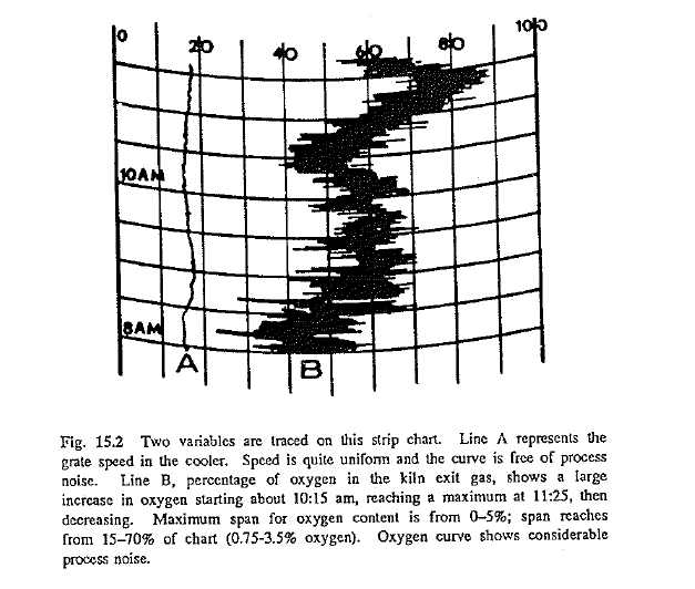
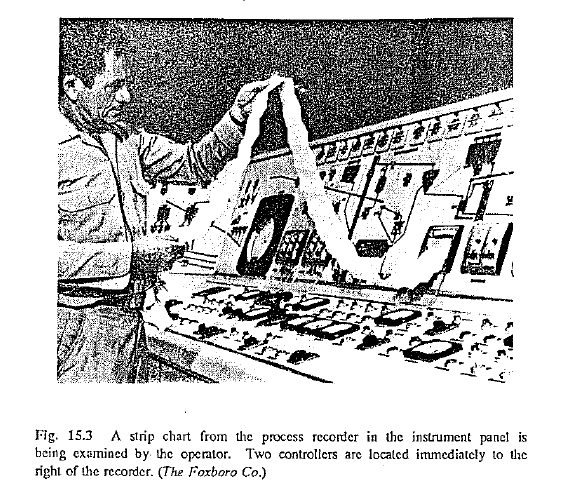
Regardless of whether a kiln is manual, automatic, or fully computer controlled, trends of the more important process variables are either re corded on a recording chart or displayed on the CRT. Fig. 15.2 is a portion of a strip recorder chart similar to the one being examined in Fig.15.3. This chart also shows the effect of “process noise,” the normal momentary fluctuations (but not changes) in the variable being recorded. Line A is virtually free of process noise, but Line B suffers from conspicuous noise.
A recorder, by itself, only records what the input variable tells it to record. In other words, a recorder merely takes a visible record of a process variable such as pressure, flow, temperature, or speed.
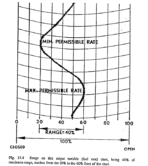
Under automatic control a controller in response to input signals, makes changes in the output variable, or control means, a process function that maintains the input variable within certin established limits. These changes or adjustments to the output variable can also be recorded (Fig. 15.4). For example, in response to variations in burning-zone temperature, the controller makes changes in the rate of fuel consumption.
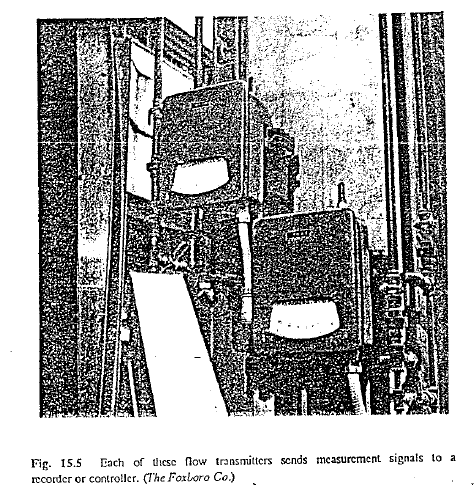
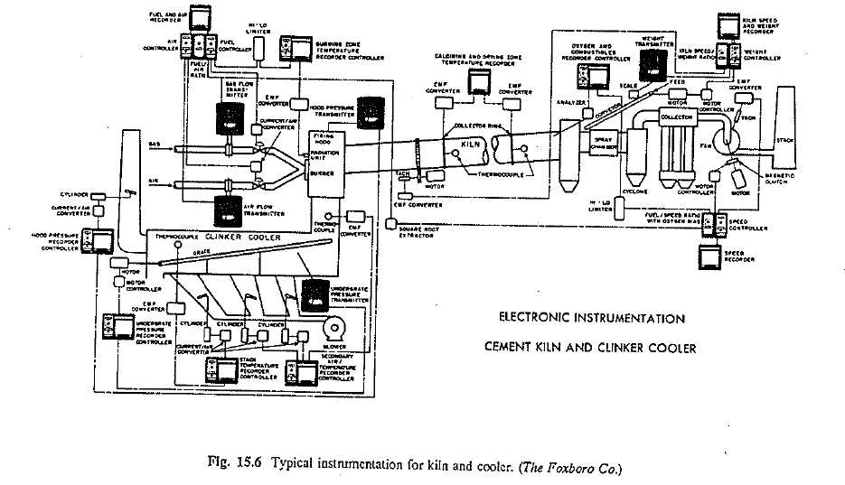
An integral part of the controller system is the transmitter. Each of the two flow transmitters shown in Fig. 15.5 sends electrical signals to the recording controller which records and controls the flow in accordance with instructions that were programmed into the controller. A schematic diagram of instrumentation for a kiln and cooler is given in Fig. 15.6.
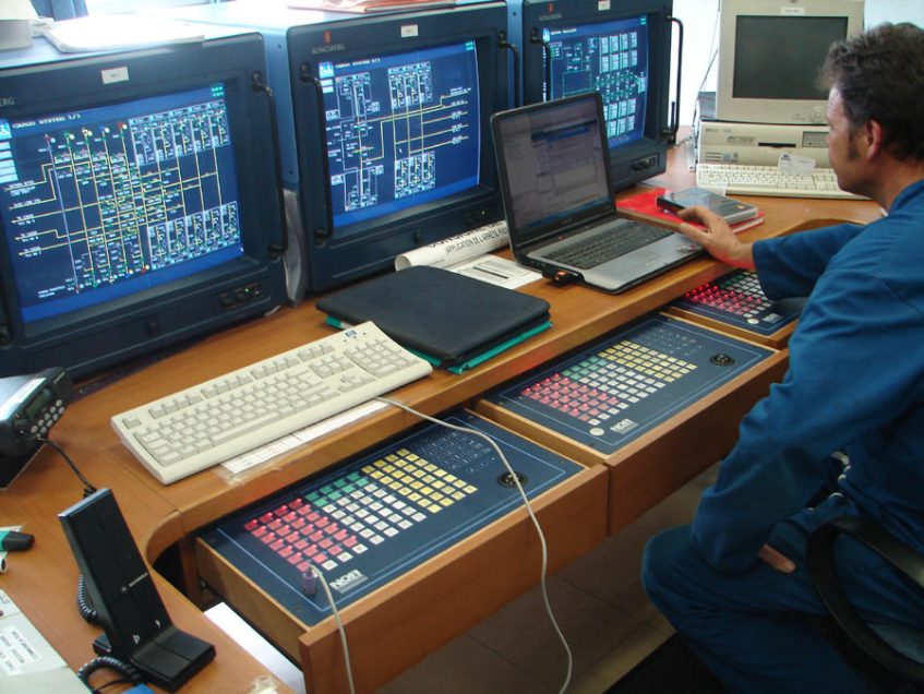
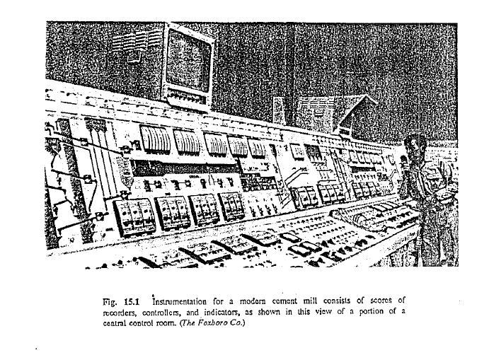
Automatic controllers are installed for the specific purpose of improving overall control of a process and eliminating costly human errors that can occur when a process is manually controlled. When a controller meets tl1ese objectives, work of the operator is made considerably easier (see Fig. 15.1).
The easy way out for an operator, when things do not go according to plan, is to take control manually and say that the controller is no good. The better approach, and the only one which can lead to satisfactory end result, is to find out why the controller does not do the job as it originally was designed to do. A serious effort in this direction will in most cases yield an answer.
When manual control is to be replaced by an automatic control, reliable instruments (in the following example, a pyrometer) have to be found and properly installed in order that a true measurement of the process variable can be obtained. Obtaining this correct value or process trend is an absolute requirement in automatic control. If this is not done, the effort to achieve automatic control is doomed to fail. Simply stated, the question becomes: How is it possible to control any variable, for example, a level in a tank or bin, if the instrument that measures this level does not work or measure properly? The answer to this question is obvious and needs no further clarification.
In order that this discussion is not drawn into fields and details beyond the control of the operators, assume that all other possible obstructions and important factors for the installation of an automatic control system have been taken care of and all necessary equipment for this type of control has been installed.
TUNING (PROGRAMMING)
The firSt and most important step is the tuning of the controller. Tuning simply means making the controller do what we want it to do, by setting a set point and tuning certain dials to get an optimum response from the controller. When these settings are properly made, the controller will make the correct response to signals received from the process equipment. When these settings are incorrectly adjusted, regardless of how well and how elaborately the system has been designed, the end results in control will not be satisfactory. An automatic controller or a computer is capable of doing only what it has been instructed to do-nothing more and nothing less. A mistake on automatic control is far more serious than a mistake on a process that is manually controlled. While an operator in manual control might make a mistake once in a while, an automatic controller will repeat the same mistake time after time without end, if programmed improperly.
In order to arrive at the proper setting for controller action on any process loop that is to be controlled, there are several variables that must be known before the control can be established.
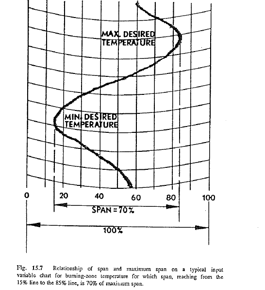
First is the span, which is the range that can be tolerated between low and high values of the input variable. It is expressed as a percentage of the maximum span. Second is the maximum span, which is the largest possible variation of the input variable that can be measured on the instruments. Maximum span is normally considered to be 100% of the chart. These relationships are illustrated in Fig. 15.7. Third, the operating range is the desired percent range between minimum and maximum allowable limits in the value of the output variable (Fig. 15.4). Usually it is not possible to operate the output device over its entire range (e.g., a valve from fully open to fully closed) so an operating range must be selected that will provide the most efficient control.
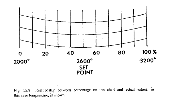
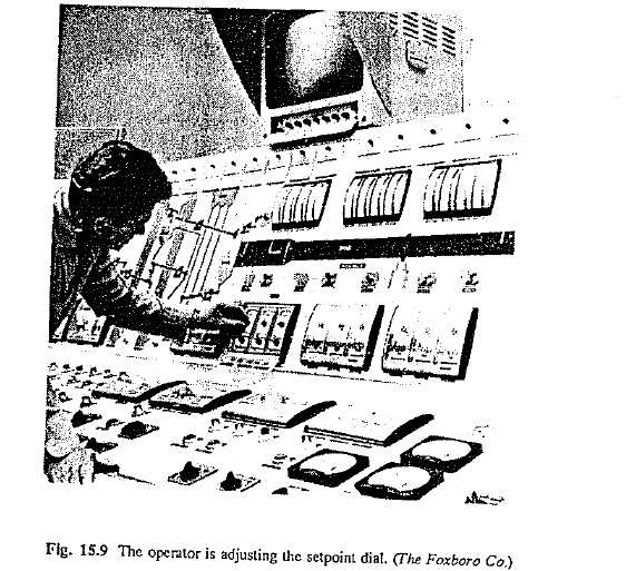
In any process-control system, tl1e setpoint is the ideal value of the input variable about which the process is controlled. Because many recorder charts are graduated in percent of chart,* it is customary to locate tl1e setpoint at a point expressed by a certain percentage of the chart, usually 50-70%. For example, consider a linear recorder so designed and operated that its maximum span of 100% represents a temperature range from 2000° at zero percentage of chart to 3200° at 100% of chart. Maximum span of this chart (0-100%) represents a range of 1200°. Assuming that 2600° is the ideal temperature at which a good clinker can be produced without overburning or underbuming, then 50% would be selected as the setpoint. Span would then be selected to cover whatever extent is allowable for the temperature to vary. Fig. 15.8 shows the relationship between percentage points on the chart and actual values being charted, in this case temperature. The operator in Fig. 15.9 is manually adjusting the setpoint on a recorder.
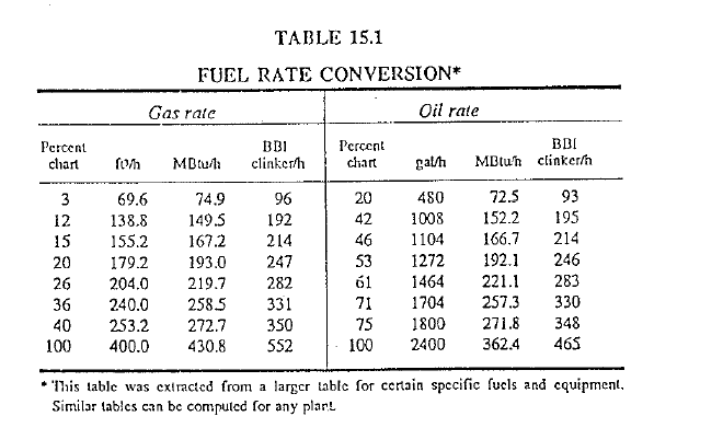
A convenient conversion table can be developed for the fuel rate (see Table 15.1). By using this table, the operator can determine the quantity of heat input at any fuel flow rate for either coal, gas, or oil at any percentage point on the recorder hart. This information is useful in determining whether the fuel is being used efficiently at any certain clinker production rate. It also tells the operator what equivalent setting to use when changing from one fuel to another.
In the discussion of manual control an example was cited in which the factors to be considered were described by a kiln operator before and after an adjustment in fuel rate was carried out. For automatic control to be successful, the controller must be programmed in such a way that it controls the temperature and adjusts the fuel rate in a similar fashion.
Most controllers have either one, two, or three action controls by which this can be accomplished. They are: proportional, reset, and rate action. In most applications proportional plus reset functions (two-mode) are utilized. When rate is utilized as a compensation for time lag in measurement, it is generally in a controller with proportional, reset, and rate function (three-mode).
Proportional Action. In a proportional-action controller, the output
variable, or control means, is set in a specific relationship to the input variable, or process variable. The mechanics of setting the controller is simply an adjustment of a dial on the controller that shows the respective settings. A large range of settings is available depending on the particular instrument in use.
An important concept involved in proportional-action control is the proportional band, this being the ratio of desired span (input) to operating range (output) expressed as a percentage. That is
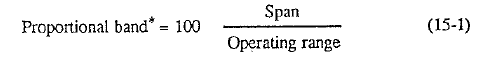
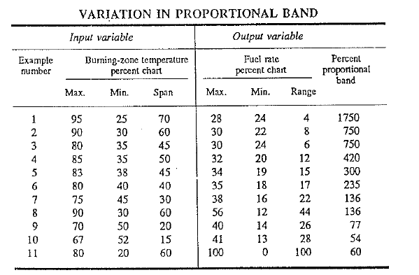
If the output variable is allowed to move through an operating range of 100% then the proportional band equals the span. If, however, the output operating range is less than 100, then the proportional band varies, as shown in Table 15.2 by some values selected at random. At a constant span for the input variable, the proportional band is increased to decrease the output range. Obviously, identical proportional bands are possible under completely different conditions in process control.
Again referring to the example in which burning-zone temperature is being controlled, Fig. 15.7 illustrates the concept of span and maximum span for the input variable under control, in this case burning-zone temperature. Span, arbitrarily set at 70% of maximum span, is selected as being the range of temperature that can be controlled by fuel-rate adjustments alone. In other words, the temperature will be permitted to vary over this range. Whenever the temperature starts to vary from the set point, the control is actuated and the fuel valve opens or closes as required depending on whether the temperature is below or above the setpoint. This is illustrated in Fig. 15.4 which shows the fuel-valve action over an operating range of 40% in response to the temperature input shown in Fig. 15.7.
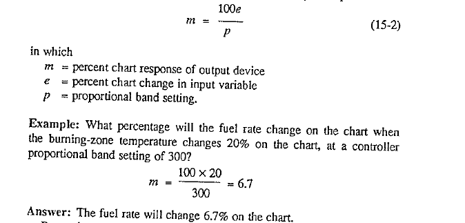
Selection of proportional band settings can have a significant effect on the reaction of the output device. Fig. 15.10 is a stylized drawing of a recorder chart showing the burning-zone temperature deviating from set point. The output variable response is large or small depending on the proportional band. The relationship can be computed by the equation:
Proportional bands are changed according to the response of the process.
For example, a water-level recorder might be set once and never changed. Kiln burning-zone temperature control, on the other hand, is more dynamic, and requires daily checking by an experienced person who is qualified to make any adjustments that may become necessary. Proper ;valuation will avoid overcontrol, a common failing of the inexperienced operator, who is apt to make two or more simultaneous changes on a Controller. Changes should be made one at a time, each change evaluated before going to the next one (if another one is actually necessary).
The serious shortcoming of proportional action control is the failure of he system to control at the setpoint in the process under control. This means that proportional action does not necessarily bring the process variable (input variable) back to the desired setpoint when it deviates. All it does is to move the output variable in proportion to a change in the input variable.
Reset Action. Most processes require that the process variable be held at or returned to a specific setpoint for optimum and efficient operation. We have learned that proportional action does not consider the setpoint and will not necessarily return the process variable exactly to the setpoint once the process has had an upset. Another aspect of process control unaccounted for in proportional action is the process reaction time or lag. Often several minutes can pass after an adjustment has been made to the output variable before the process reacts to tl1e change. With reset action, the means are available to return the process back to the setpoint and to account for possible delayed process reactions.
Reset action causes the output device to change at a rate proportional to the deviation of the input variable from the setpoint. How often this action is carried out (repeated) is governed by the reset-lime setting on the controller. Reset time can be expressed as minutes per repeat or seconds per repeat For example with a reset-time setting of one minute the action is repeated once every minute. With a setting of 22 min, the reset action would be repeated once every 22 min. Reset action enters into the control as long as the process variable is deviating from the setpoint. As the departure of the input variable from the setpoint decreases, the amount the output device corrects is decreased, during the course of any correction. When the process variable levels off at the setpoint, reset action will stop and does not enter the process again until the variable starts to move away from the setpoint
This holds true in our example of burning-zone temperature control. When reset action is applied, the percentage change in fuel feed (fuel-valve movement) is identical to the percentage deviation of the burning-zone temperature from the setpoint. Added weight must be given to the setpoint in this instance because too high or too low a temperature can not only damage the quality of the clinker, but can also damage the coating and refractory as well as impair the overall operation of the kiln itself. With a change in the fuel rate the burning-zone temperature does not return to an acceptable level immediately thereafter. As pointed out previously, several minutes can pass before the temperature starts to reverese its deviation and move towards the setpoint This delayed reaction can be observed in other areas of a rotary-kiln system. For example, when the bed-grate drive speed in the clinker cooler is increased in order to reduce the bed thickness, a considerable length of time can pass until the thickness is at the desired level.
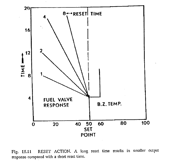
The manner in which changes in reset time affect the process is shown in Fig. 15.11, which demonstrates that the output variable or control means (fuel response in this example) can be delayed or accelerated in response to departure of the input variable (burning-zone temperature) from the setpoint. Reset times (in minutes) are indicated by the figures adjacent to the fuel-rate response lines.
Reset rate, sometimes used instead of reset time, is merely the reciprocal of reset time. For example, if reset time is 2, then reset rate is 0.5 repeats per second.
Reset action response is practically instantaneous whenever the temperature moves away from the setpoint, i.e., it reacts immediately to the temperature difference or error and starts the correction. This response of reset action has been mathematically expressed.
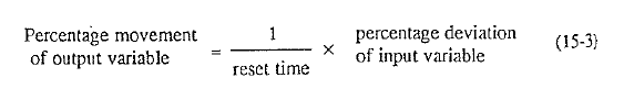
Thus, when the temperature suddenly changes 15% and the reset time is 5 min, the fuel-valve response would then be:
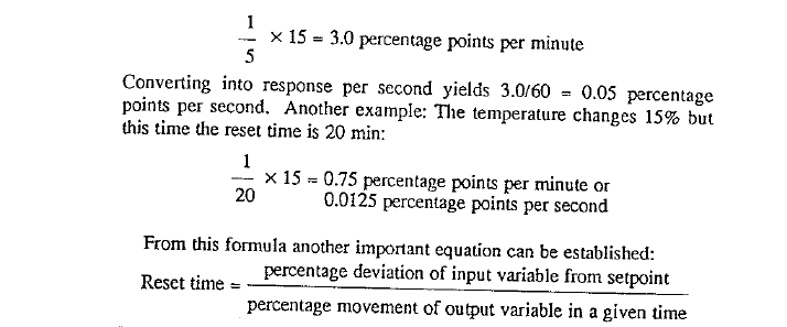
Remember to use the same time units in the result as stated in the output variable movement. That is, if the output variable movement is expressed in seconds, then reset time is likewise expressed in seconds.
Reset action eliminates cycling conditions in the process caused by the earlier-mentioned reaction time after an adjustment has been made to the control device. In setting reset time on the controller, one usually starts with a long reset time and progressively reduces the time setting until the cycling condition stops.
Derivative Action. The third and last control action available on some controllers is derivative action, or rate action. Derivative action is usually combined with proportional, or proportional plus reset action, and is almost never used alone to control a process. It is used as a compensation for time lag or inertia of the measured variable.
Derivative action causes the output device to respond proportionally to the rate· of change of the input variable when it is changing. In our example, when the burning-zone temperature moves rapidly in either direction, the fuel-rate response will be correspondingly fast, and when the temperature moves slow!y, the fuel-rate response will be correspondingly slow. In essence, derivative action is the same as the procedure most kiln operators commonly use when they control a rotary kiln manually. When they look into the burning zone and notice a large, rapid temperature change, they “hit” the kiln with a large change in fuel rate. When the temperature changes only slowly, they “nurse” the kiln with small adjustments in the fuel rate. Derivative action diminishes to zero when the burning-zone temperature stabilizes. One must remember that derivative action, like proportional action, does not consider the setpoint. In other words, derivative action ceases as soon as there is no more change in the input variable, e.g., the burning-zone temperature, and does not consider whether the temperature levels off at the setpoint or at some other temperature.
Derivative action is adjusted on the controller as a function of time just as in reset action. Thus, one refers to derivative time whenever an adjustment has to be made on the controller. In Fig. 15.12, Curve I represents a long derivative time (slow response), and Curve 3 represents a short derivative time (fast response).
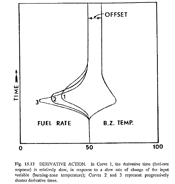
words, derivative action ceases as soon as there is no more change in the input variable, e.g., the burning-zone temperature, and does not consider whether the temperature levels off at the setpoint or at some other temperature.
Derivative action is adjusted on the controller as a function of time just as in reset action. Thus, one refers to derivative time whenever an adjustment has to be made on the controller. In Fig. 15.12, Curve I represents a long derivative time (slow response), and Curve 3 represents a short derivative time (fast response).
Proportional Plus Reset Action. From the previous discussion, it can be seen that proportional action sets the output device proportional to the change in the input variable, and reset action changes the output device at a rate proportional to the deviation of the input variable from the setpoint
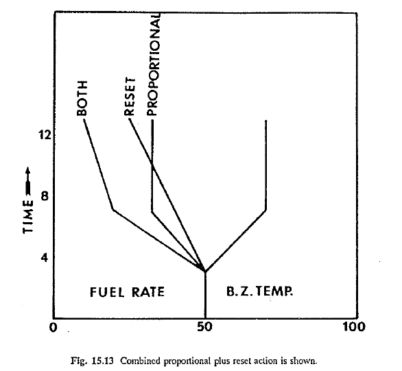
Fig. 15.13 shows how these two actions can be combined, again using
burning-zone control as an example. When no reset action exists (reset time set at infinity), the fuel-rate response would be identical to the proportional action. However, with the two control methods combined, the fuel rate is influenced by the reset action. Thus, at time increment 7 the temperature has leveled off, consequently proportional action has stopped because temperature is no longer changing.
Reset action, however, keeps the fuel rate decreasing because the process is off setpoint, and ceases to enter the process only when the process has returned to setpoint. With the two control methods combined, reset time is the time required to repeal the proportional response of the controller.
The response of the output device, under the two combined control actions, can be computed by the equation
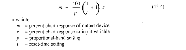
Example: What percentage will the fuel rate change on the chart every second when the burning-zone temperature changes 20% on the chart and the controller settings are: proportional! band, 300; reset time, 5 s.
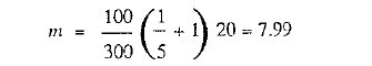
Answer: The fuel rate will change 8% on tl1e chart each second.
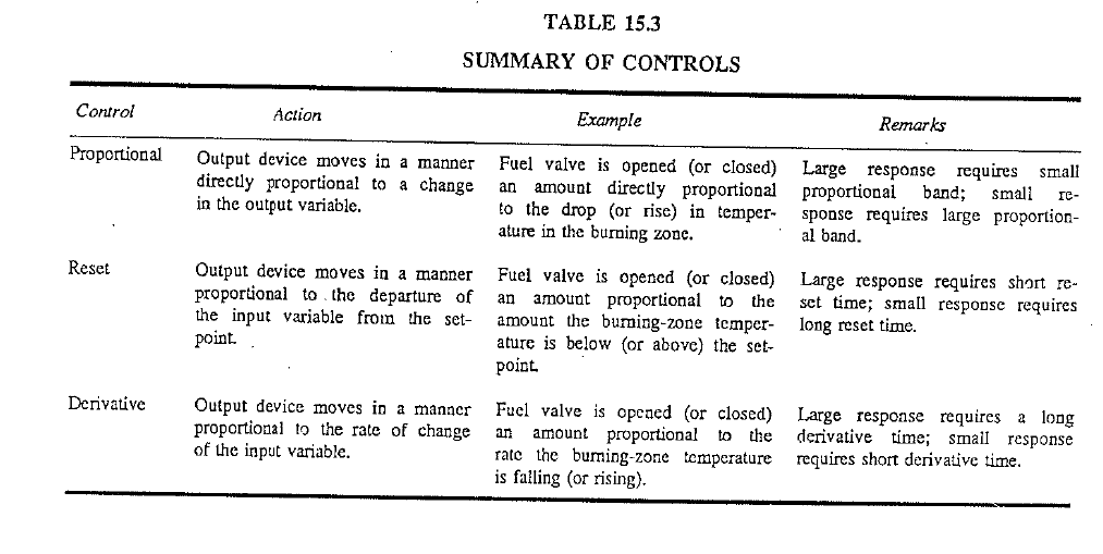
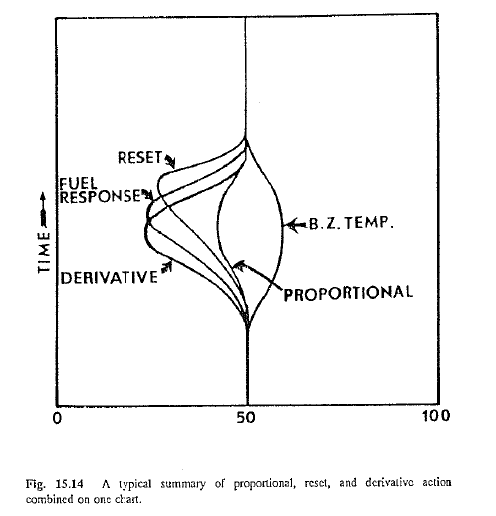
Application. At a first glance, it appears that not many tools are available with these three control actions to control a complicated process as described in the examples. However, tl1is is not so, because the possi bilities to vary these settings are almost unlimited. Table 15.3 summarizes the three basic control systems, and Fig. 15.14 illustrates how the output variable reacts under each of the systems.
Often, time and personnel to study the process beforehand are not available, which makes it necessary to find the proper settings on the controller by trial and error. In many instances, this is easier to do than calculating the settings. Many controller manufacturers recommend a wide proportional band setting. Working first by reducing the proportional band, then increasing the derivative time or reducing the r set time, an attempt should be made to eliminate process cycling. This procedure is repeated until the minimum reset, minimum proportional band, and maximum derivative time can be found so that cycling no longer exists. These settings give maximum response compatible with stability of control.
In the foregoing discussion, it has been shown how proportional, reset, or derivative action can automatically control a given process in the kiln system. It is also apparent that programming a controller is considerably more complicated than manual control. Finding the correct setting is a time-consuming task requiring prelimiilary process studies and process knowledge before the correct answer can be found. One should always keep in mind that the rewards from serious efforts made in this direction can be large not only in clinker quality and operating efficiency but also in the ease of operation. Without any doubt, one thing that gives the kiln operator the most satisfaction on the job, is to have the kiln operation so stable that only one or two small adjustments must be made during the entire shift.
KILN-CONTROL LOOPS
As previously mentioned, kiln-control concepts have become quite elaborate and sophisticated. Automation started with simple individual control loops that involved one input to a controller which in tum sent a signal to the output device to tum a motor-activated valve, damper, or drive. Technology makes it possible today to transntit and to process hundreds of process-variable inputs simultaneously to a process computer. This microprocessor, in tum, ntight be programmed and made capable of making a control-adjustment decision for one single output based on simultaneous analysis of ten to twenty different pieces of input data.
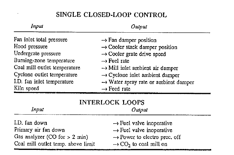
Single Closed-Loop Control. In single closed-loop control, a measurement of the variable (such as temperature, pressure, etc.) to be controlled is fed to the controller (or computer) which compares it with a setpoint and makes any adjustment in the output if there exists an error or deviation from this setpoint.
Some of the more common loops in this class are:
Cascade (Computer) Control. This is the application area that is perfectly suited for computers because in cascade control several process variables are evaluated before a decision about a necessary change is made. Take for example the aforementioned burning-zone temperature-fuel rate, closed-loop control concept. In this single loop the fuel rate is adjusted based strictly on the deviation from the setpoint of the burning-zone temperature, regardless of the oxygen content in the kiln gas or the reasons for the drop in temperature. Kiln operators would agree that this would be a very primitive way of controlling the burning-zone temperature because they themselves would not take such a simplistic approach when they control the kiln manually. For example, the operator’s thought process would follow this part:
-Notice that burning-zone temperature is dropping
Questions:
a)current and previous percent oxygen in exit gas?
b)current and previous kiln-torque or kiln-drive amps?
c)current and previous kiln exit-gas temperature?
d)current and previous J.D. fan speed?
e)current and previous feed loading in kiln?
f) current and previous kiln speed?
g)current and previous fuel rate?
-Decision: If a to g = this or that, then adjust …
The change in burning-zone temperature is the result of a disturbance that exists or happened earlier in one or several of the above-listed variables. In cascade control, this mental work is being done in a split second by a computer which evaluates these different variables, looks at their trends, and makes the adjustment based on a program that is stored in its memory. Advanced computer programs are capable of predicting the change in burning-zone temperature before it actually takes place or becomes noticeable to the operator. Coal-grinding and cooler circuits are other areas of the kiln system where this control concept has found wide acceptance. Complete automatic-control programs and systems are in existence today that can take a kiln from a cold start, control it for an indefinite length of time, and take it to a complete shutdown, without the operator having to tum a knob. Such modern control systems usually also incorporate graphic flow diagrams and trend displays of any circuit or variable the control-room operator chooses. Most important of all is that all these systems have manual control back-up capabilities to allow an operator to take over with manual control when the computer is down for maintenance. Hence, regardless of how sophisticated or automated a kiln control system is, there is clearly a need to train control-room operators in manual control of the kiln.
One can also discount the fear tha as the evolution of computer control will continue, there ultimately will be no more need for kiln operators. Perhaps it is true that the operator will have very little work to do in the future, however, there always will be a need for this skilled position. The operator’s job will become easier and the mental stress factor, that was so prevalent in the “old” times of complete manual control, wilL undoubtedly be greatly reduced in the foreseeable future.
click here to Download the Most Important 13 Books in Cement Industry
click here to Download the Most Important 13 Books in Cement Industry