Contents
To download the below and all other Useful Books and calculations Excel sheets please click here
To download the below and all other Useful Books and calculations Excel sheets please click here
Differential axial shell deflection – Is This A Problem With Your Kiln?
by Walter Gebhart,V.P., Phillips Kiln Services
Previously published in International Cement Journal, 6/98
The serious and not uncommon problem of differential axial shell deflection is a cause for aggressive mechanical wear. Symptoms are undercut side walls of the kiln’s support tires with complimentary abrasion on the tire’s retaining elements. The resulting axial play of the support tyre on the shell will produce secondary problems of uneven rolling surface wear and if the condition exists on the thrust tyre, axial shell drift which will affect the drive and shell end seals. The condition will only be found on rotary kilns with migrating tyres.
What is differential axial shell deflection?
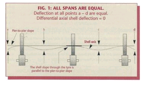
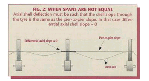
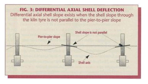
There are several categories of shell deflection, among them ovality, which is radial deflection resulting from shell rotation and secondly shell sag, which is axial deflection between the support piers. In its simplest form (when the spans are of equal length) differential axial shell deflection occurs when the amount of sag from a middle pier is not equal in the up-hill and down-hill spans. In the more general case, with unequal spans, sag to each side of the tyre must be such that the shell axis going through the tyre remains parallel to the pier to pier slope of the kiln. See Fig 2. If this is not the case we can say that the shell has differential axial deflection. Fig 3.
What is the cause of differential axial shell deflection?
The root cause is an inappropriate axial location of a set of support rollers. This means that the amount of load in the kiln along with the shell weight itself, is greater in one direction from the support as it is in the opposite direction. The direction being axially up-hill vs. down-hill or vice versa. It is uneven load distribution. Kiln design engineers are careful to properly position the supports to avoid this problem but kilns in use for many years undergo modifications to accommodate changes in processes or to make use of different refractory materials. Many kilns have shell length and piers added or subtracted. Any such change may result, unavoidably or unintentionally, in a load distribution that causes differential axial shell deflection.
How can this condition be identified?
Aggressive wear on the sides of the tyres and their retaining elements is a symptom already noted but there are other causes that produce the same symptoms. How can one be sure that differential axial shell deflection is a factor? The more common causes of aggressive wear should naturally be eliminated first. This means, roller skew, alignment, flat non-tapered rolling surfaces, and properly secured and sloped base frames, etc. must all prevail. If, and when all these conditions are reasonably correct and aggressive wear still takes place, a case of differential axial shell deflection may be suspected.
Can differential axial shell deflection be measured?
Although it is not commonly done, alignment measurements made using “The Direct Method For Aligning Rotary Kilns” (ZKG No.11/95) could directly measure this condition if additional points were to be included in the survey. Ovality measurement, a much easier and quicker procedure to perform, can also show the presence of differential axial shell deflection. Although ovality is a measure of radial (and not axial) shell flexing it can be used to show indirectly the presence of differential axial deflection.
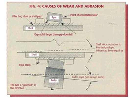
Consider Fig. #4. Firstly, the shell and its support elements attached to the shell between it and the tyre have a smaller diameter than does the bore of the tyre. This is always the case with a
migrating tyre type design. It is a very common design which has been used for decades to accommodate differential thermal expansion between the shell and the tire. Secondly, the support forces are such that the tyre has a natural tendency to sit and align itself to be flat on the rollers. Thirdly, if the shell has a greater sag in one direction compared to the opposite direction, its inclination, for the short length through the tire, will not be the same as the rollers’. There are several consequences when such a condition prevails. (a) The apparent gap between the tyre and the top of the shell will not be the same at one side of the tyre compared to the other. And (b) the difference in slope between the shell and the supporting rollers will cause the tyre to be pinched into the direction of least axial deflection. This last situation creates heavy axial loading onto the tyre’s retaining elements creating the excessive wear. Additionally (c) if the retainers are too tight a tipping component is introduced which prevents the tire from sitting flat on the rollers. Until
sufficient clearance is worn in, this will accelerate the wear. We have seen a situation where a new set of retainers were completely abraided away in a matter of weeks. Unfortunately, the additional axial clearance the tire then acquires through such wear, does not relieve the situation. The mismatched slopes continue to force, or pinch the tyre, into the direction of the least axial deflection. Consequently the wear and abrasion continue unabatedly.
This condition is also often the cause for tyres to persistently sit against either the up-hill (feed- end) or down-hill (discharge-end) retainers irrespective of various attempts to “float” them.
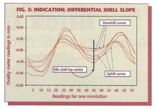
Figure 5 shows the ovality measurement raw data curves of a shell which does not sit straight within its supporting tyre. Ovality measurements typically consist of three measurements on the shell up-hill of the tire and three down-hill. These are noted as ‘A’, ‘B’, and ‘C’ up-hill and as ‘A’, ‘B’, and ‘C’ down-hill respectively. The data is graphed in the linear form as opposed to the more common radial form so that the differences in the curves are more easily seen. In this format the size of the gap at the top of the kiln is characterized by the “deepness” of the large dip in the curve as noted, fig 5. The larger the gap, the deeper the dip. It is significant to observe therefore, that the three curves down-hill of the shell, are consistently less “deep” than the three curves taken up-hill of this same tire. This measurement clearly shows there is less gap between the shell and the tire on the downhill side compared to the up-hill side. Since this pattern is consistent around the circumference, the ‘A’, ‘B’, and ‘C’ readings being 120° apart from each other, it is not a result of a “crank” in the shell. The resolution of the electronic ovality measurement instrument easily picks up this and other shell flexing characteristics. Conceivably, a hotter shell on the downhill side of the tire could also account for this phenomenon. No ovality measurement would be complete without tire, shell up-hill and shell down-hill, average temperatures being taken at the same time.
If temperature is not a factor this is the unmistakable signature of differential axial shell deflection. We say it is indirect since, no matter how clearly its presence is seen here, the amount of the difference in slope is not attainable from this measurement alone.
How can differential axial shell deflection be corrected?
Truly resolving the problem is to either change the load distribution in the kiln or change the location of the support rollers. The latter is rarely a practical option unless it is part of a massive kiln rebuild program. Even changing the load distribution in the kiln is not often a realistic option. It is only when such imbalance of loads is in itself a result of a process problem that it does become viable. The simple example here is an unusual coating or ring build-up due to a feed chemistry anomaly. The coating / ring material adds considerably weight as does the material it holds back. If this additional weight acts predominantly in one span, differential axial shell deflection will result. Reestablishing the feed chemistry then resolves both problems. Dramatic examples of this situation have been observed.
For the majority of cases, where the problem has unintentionally arisen out of a combination of circumstances, the only practical answer is to “live with it”. This does not mean accepting wear and extraordinary repair costs. Rather than eliminating differential axial shell deflection, it means designing the mechanical components to properly carry the additional loads created by it.
Many kilns have retaining elements that simply do not provide sufficient bearing area against the side of the tyres. Enlarging this bearing area, see fig 6., could significantly reduce the unit loading and bring abrasion and wear well within acceptable limits.
Lubrication of these sliding and rubbing surfaces will also improve their performance. Graphite, molybdenum, copper, aluminum and other solid lubricating materials are appropriate for this application. There are a variety of compounds specifically formulated for this application available.Solid lubrication bars that are inserted between the pads and the riding ring are an ideal solution.
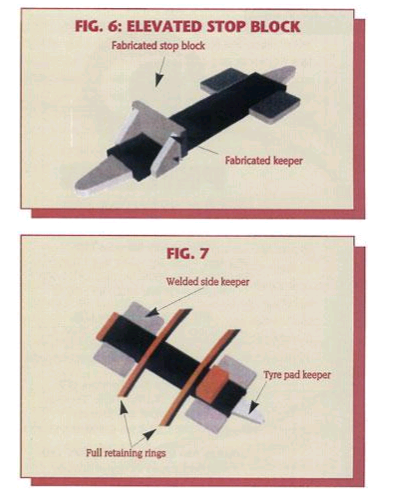
If the problem exists at the thrust tyre, enlargement of the bearing area is restricted. In this case sacrificial elements, such as retaining rings that can be easily replaced, provide superior service. (Fig 7).
Another common “fix” is to reset the bearing base or shim the support roller bearing housing to match the prevailing slope of the shell in this area rather than the pier to pier slope. This often ends up being a somewhat trial-and-error procedure but it does not have to be. It is possible, as stated before, by determining the elevation of several centers of rotation actually to measure the prevailing slope of the shell as it passes through the tyre. This can only be done with the appropriate kiln alignment measurement method, namely by the Direct Method of Kiln Alignment (The Method by Centers of Rotation). Once the prevailing local shell slope is known, accurately setting the base or calculating bearing housing shims is straightforward.
An even better although more costly approach is to utilize a pivoting roller support base. This requires completely re-building the top of the pier and installing such a new base. New, two support, gear-less, trunnion driven kilns use this concept. This has a further and very significant advantage because the roller is then free to follow the inevitable tyre wobble as well. This will greatly reduce the wear and tear on all the support elements.
The saying “an ounce of prevention is worth a pound of cure”, is a cliche, but it is still valuable conventional wisdom. When purchasing a kiln and more importantly when modifying a kiln, either its refractory layout, adding dams or changing shell length and or the number of its piers, closely analyzing its axial deflection curve must not be omitted. Differential axial shell deflection is a lot easier to prevent on the drafting table than it is to resolve once the kiln is in operation.