EVERYTHING YOU NEED TO KNOW ABOUT CEMENT KILN REFRACTORIES
Contents
Characterization of Refractories
Introduction
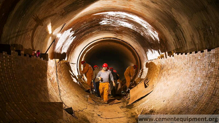
In the journey of mankind from cave to skyscraper, the Portland cement played a very important role. The modern civilization owe a lot to the contribution of cement and concrete as a building material for construction of bridges, buildings, roads, dams, tunnels, and tall structures which are being used by the people everywhere in every walk of life.
The Portland cement is manufactured by high-temperature reaction of clay or shale with calcium oxide of limestone or chalk to form cementing phases like dical-cium silicate and tricalcium silicate. This high-temperature reaction takes place inside a reactor called kiln. To contain the temperature inside the kiln and various other accessory equipments, on a continuous basis, to make the manufacturing pos-sible on industrial scale, the Refractories play a very important role. A refractory lining inside the reactor maintains the temperature range of the reactor metal struc-ture within a tolerable limit. The Refractory lining also inhibits the heat flow from inside of the reactor to outside and thus helps conserving the energy, which provides economy to the process. Without the availability of a proper Refractory, it would have not been possible to produce cement in industrial scale, economically.
Refractories are basically serving two purposes: firstly to contain the high tem-perature required for the process to produce cement clinkers and secondly to insu-late the reactors to inhibit the flow of energy out from the system. Two different types of Refractories are used to serve these two different purposes. In the first case, the dense Refractories are used to contain the temperature, and in the second case, the insulating Refractories are used to insulate the energy flow out of the system conserving valuable energy.
In the metallurgical and process industries, the Refractory practices are continu-ously getting changed, both, because of changing demand of technology at the users’ end and the availability of advanced material, which gives better perfor-mances and better economy. The cement industry is not an exception to that.
Refractory Materials
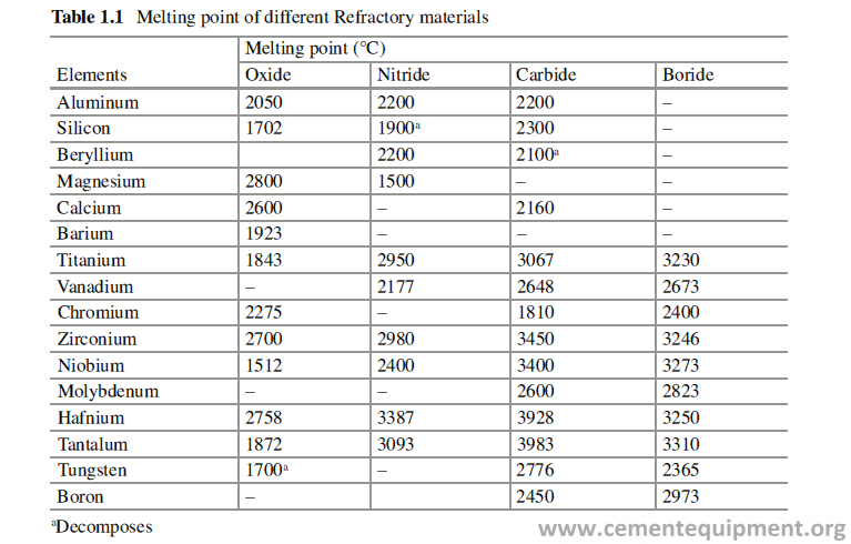
The Refractory materials are inert inorganic solid materials which are stable at high temperature in contact with corrosive solid, liquid, and gas and can retain its physi-cal shapes and structural strength at high temperature. These are mainly oxides, carbides, nitrides, and borides of aluminum, silicon, alkaline earth metals, and tran-sition metals. Table 1.1 furnishes a comprehensive chart of different refractory materials with very high melting point.
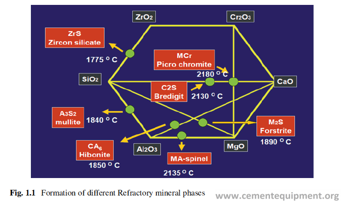
Out of all these materials, very few qualify to be used in industrial scale, because of their instability under normal atmospheric condition or because of the rare availability and high cost. For example, barium oxide or calcium carbide and aluminum carbide react very fast with atmospheric moisture. Vanadium, niobium, molybdenum, haf-nium, etc. are too expensive to be considered for Refractory application. Finally, the oxides like Al2O3, SiO2, MgO, CaO, Cr2O3, ZrO2, and carbon in different mineralogi-cal form, individually or in combination (Fig. 1.1), are used most widely to manufac-ture refractories for all metallurgical, chemical process industries and in other applications. The criteria of selection, of the abovementioned materials, are their abun-dance in nature, stability, and ease of processing to manufacture Refractory products.
The source of the raw materials can be natural or synthetic. The raw materials used for Refractory manufacturing are mainly naturally occurring minerals like bauxite, magnesite, clay, etc. which are mined and processed before being used for refractory manufacturing. Some synthetic materials like mullite (3Al2O3·2SiO2), fused alumina (Al2O3), silicon carbide (SiC), spinel (MgO·Al2O3), etc. are also being used widely in Refractories for cement industry. Properties of the naturally occurring raw materials may vary considerably from one country to another, because its geological formation and associated impurities vary.
Refractory Properties
Refractories are characterized by their chemical and physical properties and are used to correlate its behavior in actual high-temperature application.
Specific Gravity
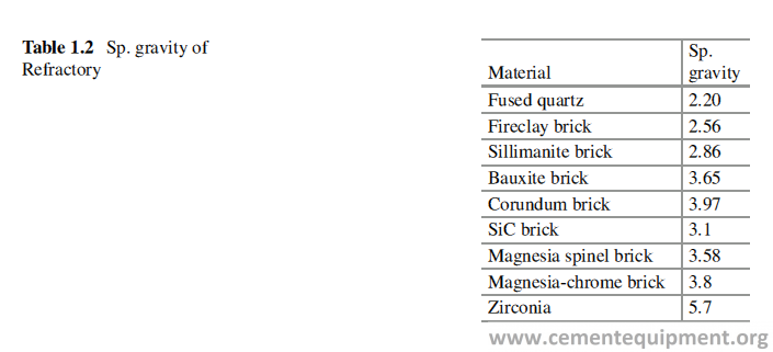
All different Refractory minerals have different densities, and it is a fundamental property of the material. Refractory materials can be identified by their specific gravities. Specific gravity can be determined by making powder of the sample of a specific size and using a specific gravity bottle and a balance. Table 1.2 gives the specific gravity value of some Refractory bricks and Refractory minerals.
Bulk Densities
It is the mass of the material per unit volume including pores. For same kind of Refractory, the bulk density can vary. The higher is the bulk density, the lesser will be the porosity and normally more will be the mechanical strength. Bulk density is different from the true density in the way that the total volume considered in the calculation is the sum of the volume of both material and pores. Therefore the value of true density is always more than that of the bulk density.
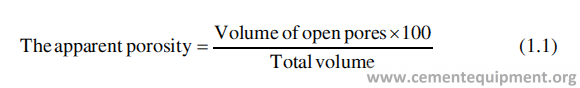
Apparent Porosity
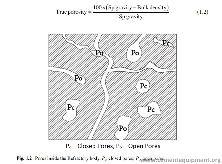
Refractories contain pores; some of the pores are open and connected and some are closed (Fig. 1.2). Total volume of a refractory body = volume of the matter + vol-ume of the open pores + the volume of the closed pores. The apparent porosity of refractory, expressed in %, is defined as
It is a very important property and influences the mechanical strength, corrosion resistance, and thermal conductivity of a Refractory. Porosity and bulk density of a refractory are inversely related. The lower the apparent porosity, the more will be the bulk density, mechanical strength, thermal conductivity, and corrosion resis-tance of the body. Besides total pore volume, the pore sizes are also very important to influence the corrosion resistance and thermal conductivity of the Refractory. The smaller the pore sizes, the better is the corrosion resistance and the lower is the thermal conductivity. True porosity is the total volume of open and closed pores. It is expressed in % and is defined as
The test for dense brick can be done as per the method ISO 5017.1988 of International Standard Organization and for insulating shapes the test is carried out by the method given in ISO 5016.1986.
The volume, size, and structure of the pores have close relationship with the penetration of slag and the permeation of gases inside the Refractories. The pore diameter in dense and fired refractory materials is in the range of 0.1–100 millimi-cron (μm). Larger pores are found in insulating refractories. Refractory castables have high share of pores below 1 μm.
Permeability
It is the measure of flow of gases through pores within the Refractory body, and it indicates the extent of pore linkage. Permeability of Refractories gives an indication on how well the Refractory will stand up to molten slag, a melt or to a gas penetration.
Specific gas permeability is defined by the equation given below, with laminar gas flow:
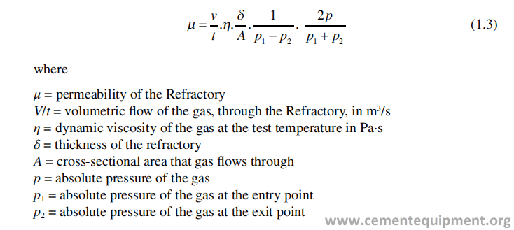
The factor 2p/(p1 + p2) = 1 for small pressure differences.
The unit of gas permeability is m2. The value for the gas permeability of refractories is usually very low and is normally expressed as μm2. The previously used unit was perm or nanoperm and 1 μm2 = 10 nPm.
Gas permeability of the refractories is determined by the share of pores with diameter greater than 10 μm. Gas permeability decreases substantially with increas-ing temperature and the increasing viscosity of the gases at higher temperature. A decrease of 50% permeability can be expected at 500 °C temperature. At higher temperature the closure of microcracks also bring down the permeability.
The permeability of a Refractory to gas can be determined by ISO standard method 8841.
Mechanical Properties
At ambient temperature these properties gives an idea about the mechanical strength required to transport and handle the Refractory-shaped products at work sites.
Cold Crushing Strength (CCS)
In this test, the cube of a specific dimension cut from the brick sample is subjected to increasing load, until it gets crushed and the test result is reported as the value load per unit area. It indicates the adequacy of firing temperature, for shaped Refractory products, required for proper sintering and to develop the required microstructure and the quality of hydraulic or chemical bond in case of unshaped Refractories. In the unshaped products, the CCS does not remain same after heat treatment, and it decreases or increases with temperature of heat treatment. The good cold crushing strength of shaped Refractories protects them from damages during handling and also from mechanical abuses in service. CCS can be deter-mined following the method given in ISO standard method 10059-1 and 10059-2.
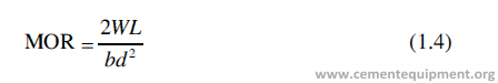
Modulus of Rupture
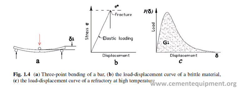
The test is conducted by putting the bar of a specified size cut from the Refractory body on two-point supports and applying load on the middle of two supports till the bar breaks (Fig. 1.4a). It is calculated as
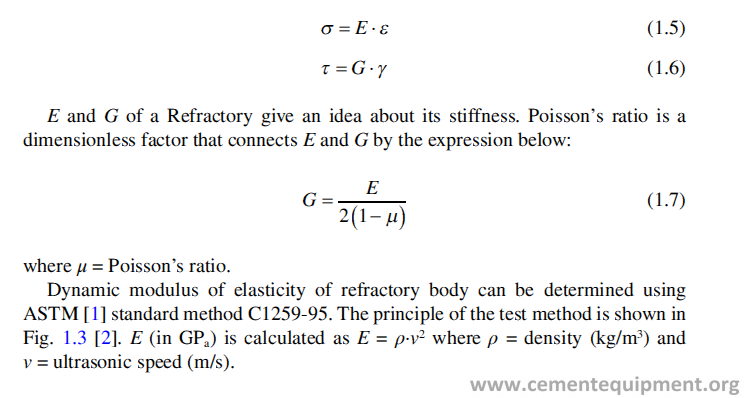
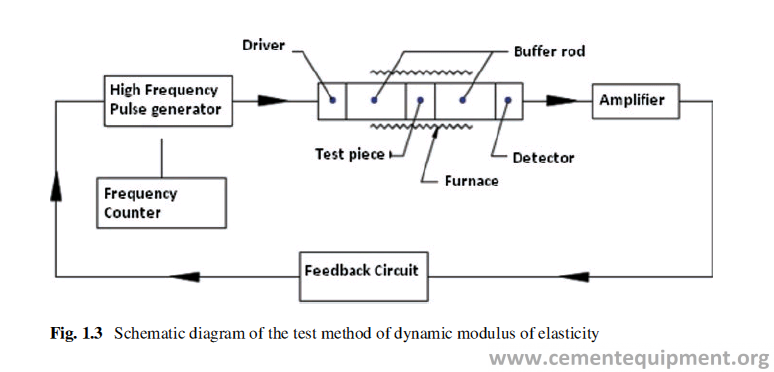
Modulus of Elasticity, Poisson’s Ratio, Hardness
It defines the stress-strain relationship and is a fundamental property of material. Like any other material, the Refractories also obey Hooke’s law, and, accordingly, it exhibits a linear relationship between applied stress (σ) and the mechanical defor-mation (strain = ε). The proportionality constant between the two is modulus of elasticity, E, when the stress is compressive or tensile. If shear stress (G) or torsional stress (τ) is applied, the strain is γ, and the proportionality constant is called shear modulus, G. Thus the mathematical relations are
Fracture
Refractories are composite brittle material at ambient temperature, and its frac-ture process is different from that of high strength single-phased ceramic material with fine grain size. Refractory lining is to withstand different mechanical and thermo- mechanical stresses developed during its use. For example, mechanical stresses generated because of ovality in the kiln shell or thermo-mechanical stresses generated during heating and cooling of refractory lining.
The brittleness of a material can be visualized from the load-displacement curve of that material under three-point bending as done in Modulus of Rupture Test (Fig. 1.4a). If the load-displacement curve shows a pattern like that in Fig. 1.4b, it will be considered as brittle material [3].
But it is to be borne in mind that Refractories are not very strong, by nature, and need not to be very strong also, because it is not used to carry any load except its own weight. The main purpose of Refractory lining is to protect the equipment steel casing or shell, from high temperature. The strength of refractory at higher temperature is of more concern to the Refractory engineers than its strength at ambient temperature. When the HMOR of Refractory is plotted against the tem-perature, it exhibits a maximum value and then decreases rapidly with increase of temperature.
The magnitude of the maximum strength obtained at a temperature between 600 °C and 1400 °C, depends upon the type of Refractory. The displacement curve of a Refractory if plotted against load at high temperature shows a curve as in Fig. 1.4c, which shows no more brittleness and plastic flow in the material. Thus, it is very important to understand that Refractories are brittle material with low strength at low temperature and becomes still weaker at elevated temperature, but it develops plasticity above 600 °C and becomes much less brittle [4, 5].
Microcracks always exist in refractory body with coarse grains. When a stress is applied on the refractories, some of the cracks may propagate to cause failure of the Refractory. The strength of the refractory body depends on the dimension of the crack. The fracture toughness KIC is proportional to the square root of the critical crack length (Eq. 1.4) [4]:
![]()
![]()
where σ is the critical stress, Y is a geometric factor, and C is the critical crack length. The higher is the fracture toughness, the more difficult it is, to initiate and propagate a crack.
For Refractories the fracture toughness remains within the value 0.5–1.2 MPa·m0.5.
Wedge-Splitting Test
Technologists have devised a test called wedge-splitting test which gives the idea about the toughness of a refractory or its resistance to crack under the influence of mechanical stresses. The schematic diagram of the devise is shown in Fig. 1.5 [5]. A sample of 100 mm × 100 mm × 75 mm is cut out of the brick and is provided with a starter notch, and two side-guided notches are taken and are put into the testing machine, and the load is applied on the wedge vertically [6, 7].
The application of the vertical force Fv develops two horizontal forces FH and causes the splitting of the sample. During the testing process, the displacement is recorded. From the load-displacement diagram, the specific fracture energy can be determined by integration:
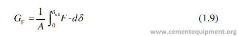
where δult is the ultimate displacement before splitting of the test sample, A is the area of projection of the fracture surface, and GF is the specific fracture energy in N/m2.
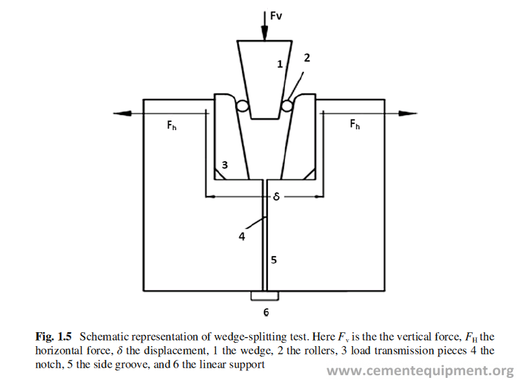
where β = angle of the wedge in Fig. 1.5.
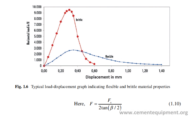
The higher the value of the GF, the tougher will be the Refractory for an applica-tion. The same test can be carried out in higher temperature also. This test becomes very useful to predict the behavior of basic Refractories in the application of burn-ing zone in cement rotary kiln. The typical load-displacement graph of wedge- splitting test is shown in Fig. 1.6 [8, 9].
Abrasion Resistance
This test becomes important for the application where the Refractory lining is exposed to moving gases, liquid, or solid. The higher is the velocity of the moving particles, the higher will be the abrasion. Two standard testing methods are followed to com-pare the abrasion resistance of Refractory body, namely, ASTM C704 or BS 1902.4 and EN 993-20 – the grinding method according to DIN 52 108 or DIN EN 102.
The abrasion resistance of Refractories depends on the intrinsic hardness of the grains in the bonded structure and also depends upon the microstructural features,
e., grain size, porosity, pore sizes, etc. Correlations exist between porosity, cold crushing strength, and cold modulus of rupture, which can be utilized for the rough evaluation of abrasion resistance. But the prediction of abrasion resistance, based on strength factor alone, is insufficient, because the bond phase of the refractory, the abrasive media grain size, grain morphology, and the angle of impingement of the grains have tremendous influence on abrasion resistance [10–12, 14]. Abrasion gen-erally decreases in a fired brick with increasing temperature [13, 15]. It can be zero when the brick surface attains a visco-plastic state.
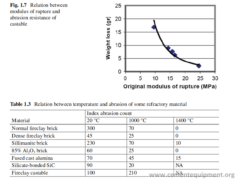
In monolithic Refractories, a general relation is known to exist between abrasion resistance and the modulus of rupture; the higher is the modulus of rupture, the bet-ter is its resistance to abrasion (Fig. 1.7) [11]. Abrasion loss is highest when the impingement of the particles on the refractory surface is at right angle, but it does not hold good when the impinging particles are much smaller compared to the aggregate size of the monolithic refractory. When the size of the impinging particles are much smaller than the aggregates, then the matrix of the monolithic refractory undergoes abrasion first, although the abrasion resistance of the aggregate may be very good, and loosens the aggregates, which falls off. Therefore, in that case, to withstand the abrasion of dust laden gases, the matrix must have to be abrasion resistant, and use of abrasion resistant aggregate alone will not be effective. If the impinging grains are larger than the average aggregate size, then both the aggregate and the matrix are removed together and both need to be abrasion resistant.
Abrasion resistance of a refractory can be determined following ASTM C704-94 standard. It is a comparative method to test the abrasion resistance of two or more products under identical condition.
The abrasion resistance of a Refractory surface in service can change drastically as a result of corrosion or by a coating on the surface. Extensive abrasion and ero-sion can also occur when hot gases (even dust unladen) pass over the lining at high speed. Table 1.3 shows the variations of abrasion of some of the refractories with temperature.
The abrasion results in the wear of the refractory lining. For a preheater kiln, the normal wear rate is about 0.6 kg/ton of clinker produced.
Thermal Properties
Pyrometric Cone Equivalent (PCE)
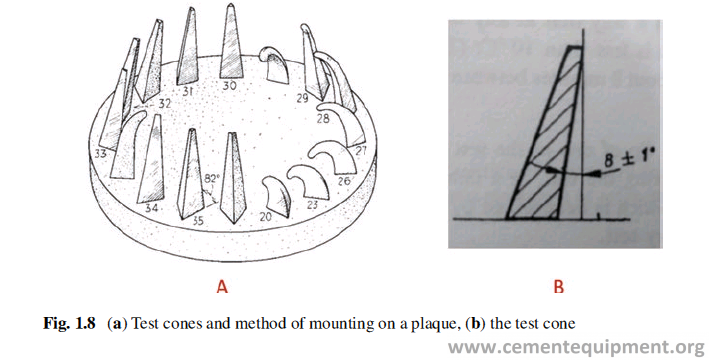
Most of the refractories are made of the naturally occurring raw materials, which contain some inherent impurities. Sometimes the presence of the impurities brings down the softening point of the refractory. Refractory products are normally a com-bination of different raw materials and do not have sharp melting point similar to pure crystalline material. Depending upon the quality and quantity of impurities, the liquid phases are formed at elevated temperature. The quantity of the liquid and its viscosity dictate the softening behavior of refractory. The PCE test gives an idea about the softening temperature and behavior of the Refractory material. From the idea of softening point, we can roughly estimate the MST (maximum service tem-perature) which can be considered as 200 °C below the PCE. The PCE value can also be used to compare the refractoriness of two refractory products from different sources or two similar raw materials from different sources. In this test the Refractory material is ground fine and made in the form of a cone of a specific size. The cone is mounted on an alumina plate (Fig. 1.8) along with few standard cones having a definite softening temperature and put in a furnace, and the temperature is gradually raised till the test cone starts bending along with another standard cone. The softening point of the test cone is reported as the cone number of the standard cone along with which it bends. The test method in ISO528.1983 can be followed to determine the PCE.
Reversible Thermal Expansion (RTE)
Like all other materials, the Refractory also expands when heated and comes back to its original dimension on cooling. The reversible thermal expansion values of different types of Refractories are different. For construction of the furnace lining, this is an important parameter to be taken into consideration, because the provision has to be kept for expansion of the Refractories, during actual operation of the fur-nace, when the lining gets heated up.
In the Refractory industry, it is expressed as % expansion from room temperature to a certain temperature. For example, if the length of a Refractory bar of length L1, on heating to a certain temperature, becomes L2, then the thermal expansion of the body at that temperature is
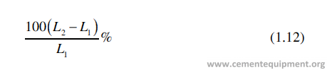
If the provision for expansion is not kept in a lining, tremendous amount of stress can be generated which may lead to collapse of the lining.
The thermal expansion is measured by the instrument dilatometer.
Permanent Linear Change (PLC) on Reheating
Refractory bricks, during the course of manufacturing, when fired at high tempera-ture, generally change in dimensions. It either shrinks or expands. It is because of solid-state reaction, forming liquid phases or because of some phase transformation. The kinetics of the solid-state reactions, generally, are very slow and never attains equilibrium in the course of the firing process, adopted during manufacturing. Therefore, the Refractories, when exposed to high temperature for long duration in service, change dimension often, which is irreversible and is known as permanent linear change (PLC). It is also expressed in %, similar to RTE. This property is determined by heating a bar, cut out from a Refractory body, at a specified tempera-ture for specified time. Initial length and the length after the firing are measured to determine the % PLC. Refractories, sometimes, are designed purposefully to have a positive or negative PLC. The PLC of a refractory product can be determined fol-lowing ISO standard method ISO2478.1987.
Thermal Conductivity
It is the fundamental property of a material and can give the estimation of heat flow through a material. Heat energy flows from high temperature, inside the furnace, to low temperature ambience, outside the furnace, through Refractory lining of the furnace. In a steady-state operation of a furnace, after a part of the thermal energy is absorbed by the furnace construction material, there is a steady outflow of energy from the system, and it is a very important factor to decide the economy of the pro-cess. Thermal conductivity of Refractory lining material is thus an important param-eter for designing the furnace lining.
The thermal conductivity is different for different material, and it is a function of temperature and atmosphere. That is why the thermal conductivity at mean tem-perature is used for design purpose. The major factors that affect the thermal con-ductivity of Refractory material are the mineral composition, the amount of amorphous material, its pore volume, pore size distribution, and temperature. Thermal conductivity also depends upon the composition of the gases surrounding the refractory. The thermal conductivity of an aluminosilicate Refractory is much higher in hydrogen atmosphere than what it is in normal atmosphere. Thermal con-ductivity is a difficult property to measure in a steady-state method, because it takes a very long time to attain steady state and to maintain it. Therefore unsteady-state method which is easier and saves time is widely used, and one of these widely used methods is hot wire method.
Thermal conductivity can be measured following the method given in ISO- 8894.2.1990 or 8894.1.1987.
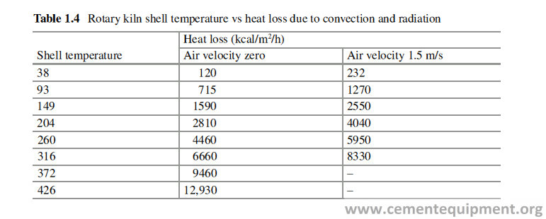
Thermal conductivity of the refractories used in cement industry is important because the cement manufacturing is an energy-intensive process. The heat loss due to radiation and convection from the surface of the kiln shell is substantial, and if it cannot be controlled, the energy cost will go up. Table 1.4 shows the heat loss from the surface of the rotary kiln shell, per unit area per hour in case the ambient temperature is 21 °C and air velocity zero and 1.5 m/s, respectively [14]. The heat loss is quite substantial and can be calculated for the whole kiln of a known diameter and length.
Heat Capacity (Cp)
It is a fundamental property of the material. This gives an estimation of the heat stored in Refractory structure in a furnace. Cp value is important, when it is required to calculate the heat required to raise the temperature of the Refractory to a certain temperature.
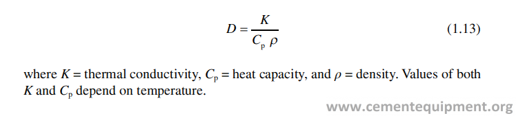
Thermal Diffusivity (D)
The thermal diffusivity is a measure of how quickly a body can change its tempera-ture. It is defined as
Thermo-mechanical Properties
The refractory materials are used in high temperature and different types of com-pressive, tensile, and shear stresses act on the refractory body at high temperature. The refractory must be able to withstand those stresses at high temperature. The thermo-mechanical properties of the refractory give an idea about the capability of the refractory to withstand those stresses at elevated temperatures. The thermo- mechanical properties and some tests, devised to measure those properties, will be discussed here.
Hot Modulus of Rupture (HMOR)
This is similar to three-point bending test performed in cold modulus of rupture, but it is performed at higher temperature inside a furnace, and the HMOR value is calcu-lated using same formula. HMOR value indicates the tensile stress the refractory can withstand at certain temperature. It gives an idea about the bonding strength between the matrix and the grains, in the Refractory body. It is influenced by the amount of liquid generated at the test temperature, its viscosity, and the microstructure, i.e., the nature of porosity, microcracks, etc., and their distribution in the Refractory body. This test can be carried out following the method given in ISO 5013.1985.
Refractoriness Under Load (RUL)
Refractories deform when put under a compressive stress at elevated temperature. The deformation is mainly due to the formation of liquid phases formed in the matrix of the refractory body at elevated temperature. The extent of deformation depends upon the temperature, the compressive stress, and the quantity and viscos-ity of the liquid phases formed. The higher is the volume of the liquid phases formed and lower is their viscosity, the higher will be the deformation at high temperature. Higher temperature and higher compressive stresses lead to more deformation.
RUL measures the temperature at which a specific deformation of Refractory occurs and gives an idea about the load-bearing capacity of the Refractory at high temperature. RUL can be determined following the test method given in ISO1893.1989.
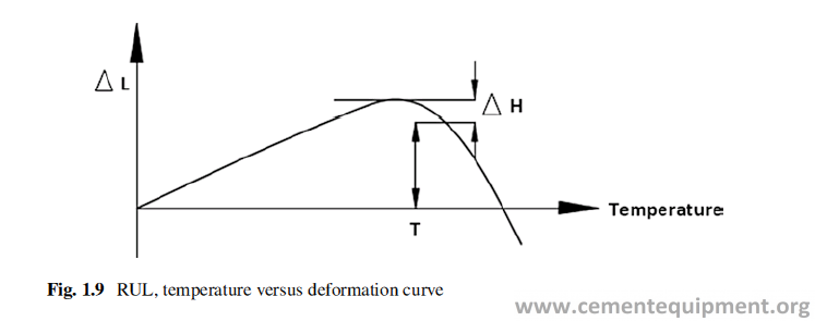
In this test the cylindrical sample of diameter 50 mm and height 50 mm is drilled out of the Refractory body and is put into a vertical tubular furnace, on one of its flat side. A load of 0.2 MPa is applied on the surface through a graphite rod, and tem-perature is raised at a rate of 5 °C/min. The change of length of the sample is mea-sured during heating and plotted against temperature as a curve shown in Fig. 1.9. The temperatures at which deformation of 0.2%, 2%, and 5% occurs are denoted on the temperature vs deformation curve as T0.2, T2, and T5. The deformation shown in the figure is [{ΔH(in mm)}/50] × 100% = 2ΔH %.
Creep
This property characterizes the time-dependent deformation of the refractory at high temperature. When a refractory is subjected to a compressive stress for a long time, then its deformation behavior over that period can be predicted by this prop-erty. In this test, the cylindrical sample of 50 mm diameter and 50 mm height is drilled out of the Refractory under testing. The sample is put into a cylindrical fur-nace and temperature is raised to test temperature and a load of 0.2 MPa is applied. The temperature and the load are kept constant. The deformation of the sample is measured against time over a long duration to get its creep behavior. The creep in compression can be measured following the ISO method 3187.1989.
Thermal Shock Resistance
Refractory lining faces temperature cycling during its campaign for various reasons, for example, because of start-up and shut down of the kiln, because of variation in fuel rate, etc. In most of the cases, because of exigency of production, the heating and cooling are made fast. The fast temperature variation in the kiln or furnace causes the development of thermo-mechanical stresses in the refractory lining.
Differential temperature in the lining results to differential expansion in the same body and develops mechanical stresses, either compressive or tensile in nature, which ultimately damages the refractory.
The Refractory lining develops compressive stress on fast heating and tensile stress on fast cooling of the furnace. Normally the ceramic materials are weaker under tensile stress, and therefore the fast cooling damages the Refractory more than fast heating.
The thermal shock resistance of a Refractory is related to its other properties like thermal conductivity, thermal expansion coefficient, modulus of elasticity, and rup-ture strength. The higher the thermal conductivity and rupture strength, the better is the thermal shock resistance. Lower value of modulus of elasticity and thermal expansion coefficient make the thermal shock resistance property of the body better.
Rapid temperature change on the surface of a refractory body causes large tem-perature gradient that leads to considerable stress which can be expressed by the equation below [2].
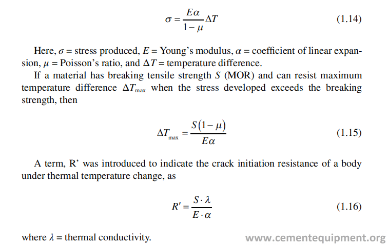
This equation says that a refractory with high strength and high thermal conduc-tivity, low modulus of elasticity and low thermal expansion the resistance to crack initiation is high.
To test the thermal shock resistance property in laboratory, normal Refractory samples of definite shape are cut out of the Refractory bricks, and the samples are heated at a definite temperature for definite time, and then it is quenched either in cold air or water for a certain time and the total process is called one cycle. The same process is continued till the refractory suffers a specified dam-age, and it is reported as the number of cycle under the specified condition of heating and cooling. The thermal shock resistance testing is carried out to compare between two or more refractory products. The PRE/R5 method of European Federation of Refractories can be used for this comparison.
Structural Spalling
Many times, during service, an altered zone is formed in the refractory lining, near the working surface. It is formed due to chemical reaction of the refractory lining, with the different materials it remains in contact, during the operation of the fur-nace. The altered layer tends to crack or fall off in the form of thin or thick layer called “peeling” or “slabbing,” even due to the formation of an internal stress caused by the small temperature fluctuation. The stress builds up, due to the mismatch of properties between the original and altered zone of the refractory as a result of min-eralogical changes and liquid phase formation. The major cause of the formation of altered zone is the chemical reaction of refractory at elevated temperature, with dif-ferent gas, liquid, and solid phases remaining in contact with refractory, forming different mineral phases. The overheating, which accelerates those reactions and the formation of the liquid phases, causes densification of the refractory body in the altered zone.
Corrosion Resistance
It is the property of the refractory which indicates its inertness to chemical reaction with the specified solid, liquid, or gas at high temperature. Due to the chemical reac-tions mentioned, the Refractory forms different products or phases which are not suitable as a Refractory material, and the Refractory stops functioning for the pur-pose it is used. The reactions are more prominent with liquid and gases, and the reaction rate increases fast with increasing temperature. The process of corrosion is very complex in nature and is a combination of chemical and physical processes. Besides the chemical reaction, the pores in the refractory allow the molten liquid or gas to permeate inside and to react further [16]. The reaction products may develop stress because of its higher volume and cause cracks in the body, which increases contact area with further enhancement of corrosion. For the physical penetration of the liquid, the rate of penetration dl/dt is governed by the equation:
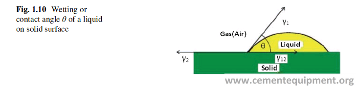
where r = radius of pore, γ = surface tension of liquid, η = viscosity of the melt, and θ = wetting angle or contact angle (Fig. 1.10). Equation 1.17 shows that higher pore size of refractory, lower wetting angle of the liquid on the refractory, and lower viscosity increase the rate of penetration. The reaction rate increases fast with increas-ing temperature and the type of flow of the fluid (laminar or turbulent) in contact.
It is very difficult to simulate the conditions of the refractory and melt reaction in the laboratory. The corrosion resistance test is a qualitative test, designed to com-pare the affinity of two or more refractory products, to react with a liquid, at a cer-tain temperature. However, to get the idea of the compatibility of a refractory to a particular liquid phase at certain temperature, tests are carried out. There are two different type of tests are normally carried out, static and dynamic.
Static Test Method
In static test, a cube of 75 mm size is cut out of the refractory under testing. A drill is made of 25 or 50 mm diameter and depth of 40–50 mm in one face of the cube. The cup made is filled with the solid with which the reaction of the refractory is to be studied, when it is in molten condition. The cube is then put in the furnace and fired till the desired temperature is reached. The sample is allowed to reside inside the furnace at that temperature for a specific time, allowing the reaction to happen, and then the furnace is put off and cooled. The refractory cube is taken out, and the cup is cut vertically to observe the extent of the reaction. It is a comparative test that is difficult to quantify. The judgment of corrosion resistance is made by visual observation only, after a refractory is allowed to undergo through a corrosion reac-tion at a specified temperature for a specified time.
Dynamic Test Method
In dynamic slag test, the melt remains in the furnace in a crucible, and an attachment holds a small bar (cut out of refractory) of a specified dimension which rotates on its axis in the melt at a desired test temperature for a specified time. Then the sample is taken out of the melt, cooled, and is visually observed for the reaction happens.
Alkali Resistance Test
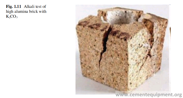
It is qualitative test and compares the alkali resistance of a Refractory with others. In this test a 40 mm hole is drilled in a Refractory brick to form a cup. The cup is filled with potassium carbonate, covered with a refractory lid and the test piece is put into a furnace, and the temperature is raised to 1100 °C and kept for 2 hours. The furnace is put off and cooled. The test piece is observed. The test piece develops crack if it is not resistant to alkali attack. The extent of crack determines its resis-tance towards alkali attack. Figure 1.11 shows the test samples after alkali resis-tance test. Different test methods are available to compare the corrosion resistance of two or more Refractory products under identical condition. It can be tested by C454-83 of ASTM standard.
Microstructure Study
Refractories are normally made of small grains bonded by a matrix of fines and glassy phase. The key elements of the microstructure are the individual grain bound-aries, pores, and microcracks. Microstructure tells about the grain sizes and mor-phology, pore sizes and morphology, orientation and distribution of the grains, matrix and pores, presence of different mineral phases, presence of microcracks, etc. All the microstructural features influence the physical properties of the Refractory. The microstructure of the Refractory cannot be seen in the naked eye and is revealed through different instrumental methods as mentioned here.
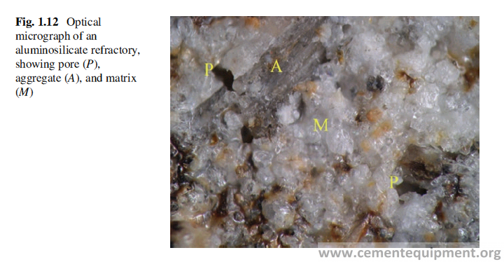
Optical Microscopy
The polished section of the Refractory or thin section of the Refractory can be seen under high-resolution microscope by either reflected light or by transmitting light. The photo can be taken to record the microstructural features. It shows the grain sizes, pore sizes, and their distribution along with that of matrix, the morphology of grains and pores, and different mineralogical phases (Fig. 1.12).
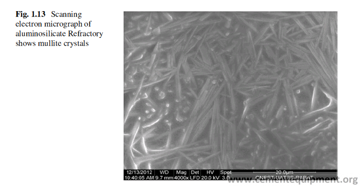
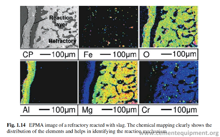
SEM and EDAX
In this instrument electron beam is used in place of ordinary light. Magnetic field does the function of lens in electron microscope. The resolution in this microscope is very high and 1000 times more than the optical microscope. It enables us to see the microstructure with much larger magnification (Fig. 1.13). The different meth-ods of testing, using electron beam, are scanning electron microscopy (SEM), elec-tron probe microanalyzer (EPMA), and transmission electron microscopy (TEM).By EPMA, any point on the section of the refractory can be chemically analyzed, and chemical map of a selected area on the sample under microscope can be obtained which is very useful to have an idea of mineral phases present and their distribution (Fig. 1.14).
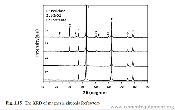
X-Ray Diffraction
XRD pattern is unique for any mineral phase.
By exposing the powder of a Refractory sample to X-ray, a pattern is obtained. When that X-ray pattern is analyzed, then different mineral phases present in the Refractory body can be known by the presence of their characteristic peaks (Fig. 1.15). The presence of the peaks indicated the presence of the particular min-eral, and the intensity of the peak gives an idea about its quantity present.
XRF
It is used for the chemical analysis of any Refractory material. In this method the powder of the test sample is used to form a pallet which is fed to the XRF machine, and on running the machine, it produces a diffraction pattern (Fig. 1.14). The stan-dard X-ray diffraction pattern is already there for different mineral. The produced X-ray diffraction pattern when matched with the diffraction pattern of the known minerals and then the mineral phases present in the sample under investigation can be known.
Classification and Features of Different Types of Refractories
Classification of Refractories
There is no rigid norm for classification of Refractories, and it can be classified in various ways. The basis of classification of refractories in different ways is dis-cussed here.
Basis of Classification
Refractories are generally classified based on different parameters, e.g.:
(a) Basicity of oxides
(b) Form
(c) Manufacturing process
(d) Method of application
(e) Insulation property
(f) Special chemistry
Let us see the classification in details.
By Basicity
The oxide Refractories can be classified according to the basicity of the oxides. Refractory oxide can be characterized by the electropositive character of the central atom in that oxide. The more electropositive is the central atom, the more basic is the oxide, and the more electronegative is the central atom, the more acidic is the oxide. Electropositive character increases from right to left across the periodic table and increases down the column.
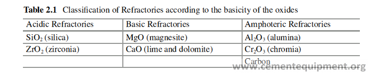
According to the position of the element in the periodic table, its oxide can be classified as acidic, basic, or amphoteric in nature. Accordingly, the Refractories can be classified as acidic, basic, or amphoteric as shown in Table 2.1. This classifi-cation has significance in selecting Refractories to be used in contact with molten slag with a known basicity. For example, basic Refractories should be selected where the basicity of the slag, in contact with Refractory, is more than 1.0 to get a reduced corrosion rate, although many other factors should be taken in consider-ation in selecting the right kind of Refractories for a certain application.
By Form
The other classification of Refractories has been made on the basis of its form in which it is produced, manufacturing process and application. According to form Refractories are classified as shaped Refractories, commonly known as refractory bricks, and the unshaped refractories as monolithic refractories. The shaped refrac-tories are delivered in the form of definite geometrical shape, and unshaped Refractories are supplied as loose powder, which is to be mixed with required amount of binder/water and applied at the site to take the shape of the area, where it is used. Figure 2.1 shows the scheme of the classification of refractories based on form.
Shaped Refractories
Shaped Refractories are made in different geometrical shapes according to the requirement of the user. The shapes are designed depending on the geometry of the furnace or equipment which is to be lined with refractory. Shaped Refractories are classified by the process of manufacturing adopted and are termed accordingly.
Pressed Shape
Different size fractions of different Refractory raw materials are mixed with a liquid binder. The mixture is pressed in a mold at high pressure in mechanical press, fol-lowed by drying and firing to impart mechanical strength and volume stability at
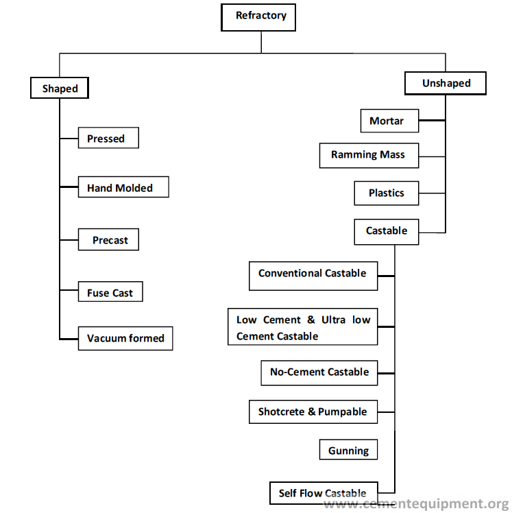
Fig. 2.1 Classification of Refractories
high temperature to the body. These products are called pressed bricks. The bigger is the dimension of the brick, the higher is the capacity of the press needed. Product with complicated shape and geometry cannot be made by this process.
Hand Molded
Hand-molded shapes are made by mixing different size fraction of different Refractory raw materials with a liquid binder and to give shape by pneumatic ram-ming in a mold followed by drying and firing to impart mechanical strength and volume stability at high temperature. These products are having lower density and strength than pressed products. This method of production is much slower com-pared to production by pressing. Only very critical shaped items are made in this method.
Precast
In this method different size fraction of refractory raw materials are mixed along with high alumina cement and other additives followed by mixing with required quantity of water. The mixture is then given shape in a mold by vibration casting or pouring. The cast body is then allowed to set and cured followed by demolding and drying to form the precast Refractory. Sometimes the cast body is fired at high tem-perature to meet the desired properties. This is also a very slow process of produc-tion compared to pressing and used to produce complicated and bigger shapes which cannot be made by pressing in mechanical press.
Fused Cast
The mixture of raw materials is melted in a high-temperature furnace and poured in a graphite mold. The mold is cooled very slowly when the melt solidifies and takes the shape of the mold. These are called fused cast Refractory shapes. Specialty of these products, are zero porosity and these are used mainly where the corrosion is the main factor to destroy the refractory, e.g., lining of the glass tank where the refractory remains in continuous contact with highly corrosive molten glass. This kind of product is never used in the cement industries.
Vacuum-Formed
This method is mostly used for making ceramic fiber insulation boards or similar products with other shapes. In this process the ceramic fiber along with the organic/inorganic binders are stirred in water at high speed to form a slurry, which is spread over a mold, fitted with fine wire mesh, and the water is sucked out under high vacuum pressure to give the shape of the body. The formed body can then be demolded and dried and heat cured to develop strength in it.
Advantage and Disadvantage of Shaped Products
The advantages and disadvantages of using shaped Refractories are:
1-The bricks made under high pressure attain very good properties like high den-sity and low porosity.
2-The laying of shaped Refractories does not demand very high skill of masons.
3-The laying process is normally manual and does not involve the use of expensive machines, although in case of rotary kiln lining, the brick laying machines are being used very successfully.
4-The total time of Refractory lining and preheating, i.e., starting of the installation to furnace ready-to-use duration, is less compared to lining with unshaped Refractory.
5-Many different shapes are required in combination with line the equipment, and inventory cost is higher compared to unshaped refractories. On nonavailability of even one shape, the total lining process may come to a halt.
Unshaped Refractories
Unshaped Refractories are normally manufactured and supplied in bags as loose powder. The manufacturing of unshaped Refractories is simpler than the shaped Refractories. In its manufacturing the different ingredients in different size fractions are mixed thoroughly in a mixer with required additives and bagged. During use, the bags are opened at the site and the powder is mixed with required quality and quan-tity of water or supplied liquid binder, in a mechanical mixer, and is rammed or cast or sprayed at desired place of installation. The unshaped Refractories can be further classified based on its application method.
Mortars
Mortars are powder materials which are used for the purpose of joining the Refractory bricks. The powder material is mixed with water or a liquid binder sup-plied along with the mortar and applied as glue on the brick surface to join two bricks. The mortar can set and harden either by chemical reaction (chemical-setting mortar) at ambient temperature or by heating (heat-setting mortar) the joined brick. Mortar can be both of basic or aluminosilicate type, used to join either basic bricks or aluminosilicate bricks. Mortar joints in the brick lining acts as a cushion to reduce the thermo-mechanical stresses generated during operation of the furnace.
Ramming Masses
Ramming masses are used in very less quantity and for very special purposes only, in cement industries. It is a mixture of coarse aggregates and fine powder with some additives, and it is mixed with water or liquid binder and rammed by hand or by pneumatic rammer at the desired area. It is normally applied to fix up the gaps which are difficult to be filled otherwise, for example, a small gap between the bricklayers and retainer plate. Ramming masses can be made both in basic and non-basic composition, but in the cement industry, the nonbasic ramming masses are used normally.
Plastic Refractories
Plastic Refractories are ready-made unshaped Refractories. These are supplied, in ready-to-use form, of small blocks, wrapped in polythene sheet. The material is unwrapped at site and put at the place where it is to be used and then stamped with wooden mallet or rammer with flat-bottomed tool. Plastic Refractories are made with aluminosilicate material only. This material is hardened fast after installation and can be dried and preheated faster, compared to castable. Because it is a ready- mixed material and binder is mixed already, it has got a low storage life, especially in hot climate of tropical countries. It has the advantage that it is a ready-mixed material, so the chance of mistakes due to wrong addition of binder or improper mixing of binder can be eliminated. It is a good material to use for lining the roof of a furnace. Ceramic anchors are used, similar to castable installation, to hold the material. Its installation is a slow process, but it can withstand fast heat up and does not develop crack.
Castable
Castables actually are the major products in the unshaped Refractory category and are made up of aluminosilicate aggregate and calcium aluminate cement (also called high alumina cement) as binder, along with special additives to impart or modify certain special properties in it. The calcium aluminate cement, like Portland cement, has hydraulic property and sets to a hard mass in contact with water. In case of no- cement castables, the liquid binders are supplied separately along with dry powder, and both are to be mixed during application. Of course, recently the no-cement cast-able has also been developed in which the water can be used for casting instead of any separate liquid binder.
Castables are the material which can be cast after mixing with water or other liquid binder (in no-cement castable), and it set hard at ambient temperature. Castables can be installed by different methods, e.g., by pouring, by vibration cast-ing, by gunning, and by shotcreting. Two major steps in the installation processes are mixing of castables with water and the method of consolidation of the castable. Mixing quality is very important, and the aim should be to get maximum flow using the prescribed water or binder content. That is possible only when the mixing is very thorough and intimate, done in high-shear mix.
The consolidation of the castable can be done by the following methods:
1-Pouring it as slurry or semi-slurry and to consolidate it with light vibration, called casting
2-Vibrating strongly a stiff thixotropic material when it starts flowing, called vibro-casting
3-Transporting and spraying of water-mixed slurry, called shotcreting
4-Spraying a dry material which is mixed with water at the spray nozzle tip, called gunning
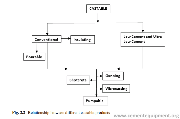
Castables can have further classification depending upon its composition, method of application, and flow behavior. The purpose of this classification is to distinguish the difference between the products which are made out of same basic ingredients but differ substantially in their rheological (flow behavior) character, drying behav-ior, etc. The relationship of different categories of castables is shown in Fig. 2.2.
Conventional Castable
Conventional castable with higher content of calcium aluminate cement requires high percentage of water to attain required flow character, and the mixing with water can be done even on the floor, although not recommended, with the help of a shovel. The setting can be controlled and modified with the addition of special addi-tives. The heat-up curve to remove water is not very critical unless it is cured at a temperature below 10 °C.
In many occasions when a shutdown is taken at any plant, the refractory lining is first inspected to check for any damage in the refractory lining. Then small patching work is usually done to repair small areas of worn out brick or castable lining by troweling or plastering the castable, mixed with water. Conventional castables are suitable for this purpose.
Low and Ultra-low Cement Castable
The low and ultra-low cement castable, have almost the same ingredients as conven-tional castable, but with lower content of calcium aluminate cement. It can attain the desired flow character necessary for vibration casting, with almost half of the water
as required in conventional castable. But it is to be borne in mind that very intense mixing is required to develop the desired flow property in the low cement castable and it is to be mixed in a high-shear mixer. Mixing of low cement castable and water in ordinary mixer or with shovels do not yield the desired flow property required for casting. This enhancement in the flow property, made by engineering the particle size distribution and addition of certain special additives, actually revolutionize the whole castable technology. Lower content of the calcium aluminate cement, as sug-gested by the name, imparts better properties to this type of castables at elevated temperature over the conventional castables because of lower content of CaO in the mix. Low cement and ultra-low cement castables develop a thixotropic property on mixing with water in high-shear mixer. The mix starts flowing only when a shear force is applied on the mix and requires strong vibration either by means of needle vibrator or form vibrator. This kind of castables forms a much denser body on cast-ing and has lower permeability compared to conventional castable, and therefore it’s drying and preheating are very critical. The casting may crack on preheating unless proper care is taken.
A further development of low cement castable technology has made it self-flow type, which, when mixed with low percentage of water, can flow very easily and requires very mild or almost no shear force or vibration for its placement. It can be used at a place where the vibration casting cannot be done and at the same time properties of low cement castables are required. This is actually an extension of the technology, developed for low and ultralow cement castable.
No-Cement Castable
No-cement castables either contains no calcium aluminate cement or a very low amount. Calcium oxide, in the cement, acts as a flux towards aluminosilicate raw materials and brings down the refractoriness of castable. Low and ultra-low cement castables were developed to reduce the content of the cement and to overcome that drawback.
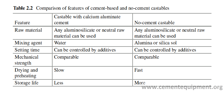
No-cement castables were developed to completely eliminate the calcium alumi-nate cement and to replace it by alumina or silica sol as the binder. It is normally two-pack system, and the powder component and the binder component (liquid) are supplied in two separate packets. The user is to mix both powder and liquid at the site and apply. It can be poured or cast similarly as calcium cement-based castable. It has an advantage over calcium aluminate cement-based castable that it can be preheated at a much faster rate than cement-based castable. A comparison of usual cement-bonded and no-cement castables is given below in Table 2.2. Now further development has made possible, the availability of a one-pack no-cement castable, in which the binder is used in the solid form and is available commercially.
Pumpable
Further progresses were made in castable technology to make it (pumpable cast-able) amenable for pumping as a water-mixed slurry, for easy transportation. By this, the mixing activity of castable with water can be kept far off from the actual site, for ease of installation job. Pumpable can be used for casting a horizontal section because the slurry can rest on its own and set.
Shotcreting
In the shotcreting process, the castable in similar way is pumped and transported through rubber hose and is sprayed through a nozzle with the help of compressed air on the target wall. It is very useful for fast installation of a large volume of refractory at a difficultly accessible site, like preheater cyclone, situated at a consid-erable height. Moreover, the fixing and dismantling of steel former, used for cast-ing, involve manpower and take time for fixing. The shotcreting method does not require any former and eliminates both time and cost. To enhance the setting of the slurry on the target wall and to convert it to a gel, so that it does not flow by its own weight, a gelling additive is added to the shotcrete material at spraying nozzle. This helps to install a thicker lining, and because a thick layer can be built up on a verti-cal wall, the requirement of former, as used in traditional casting process, can be eliminated.
Gunning
Gunning material can be made both in aluminosilicate base and in magnesia base (basic) composition. Basic gunning materials are used generally for the hot repair-ing of the refractory lining in steel melting furnaces. There is no scope of use of basic gunning material, and they are never used in the cement industries. For cement industry the gunning materials are made using formulation similar to castable but modified by adding special additives to suit the gunning process. In the process of gunning, dry material is conveyed pneumatically through the rubber hose of the gunning machine, to the nozzle. At the nozzle tip, water is added through a separate rubber pipe at high pressure and sprayed on the target area. It must set fast, must get hard quickly, and must not crack on fast heating. Gunning materials of varied speci-fications, based on aluminosilicate raw material and calcium aluminate cement mix, are used in cement industries. This method can be very effectively used for cold or hot repairing of an area inside the furnace without taking major shut down. This method is not very effective for installation of large volume of material in a short span of time. In gunning process there is always some loss of material due to rebound of the material when the gunning material hits the wall. The rebound per-centage may vary depending upon the material or the operator, but it is always there.
Special Features of Unshaped Products
The special features of the unshaped Refractories are as follows:
a)Although its manufacturing is easy, its installation requires very skilled and experienced hands with much attention. Installation of monolithic refractory requires less labor and can be automated to a large extent.
b)The unshaped Refractories are more environment-friendly materials because they do not require any high-temperature operation for its production.
C)It is a semifinished material. It is partly finished at the premises of supplier, and the final finishing is made at customer’s premises. Therefore, its quality of installation, including consolidation, drying, and preheating, is very important, unlike shaped product.
d)Normally, from the beginning of the installation to ‘ready for use’, duration is much longer in case of castable Refractories, because of longer time needed for (1) preparation (welding of steel anchors to hold the Refractory) of the surface, over which the unshaped refractory will be applied, (2) preparation of the mix and consolidation of the Refractory mass, (3) setting of the Refractory to become hard, and (4) preheating the cast lining. The unshaped Refractories comprise of large group of products with varied application method and pur- pose to satisfy the particular technical requirement of a refractory lining.
Insulating Property
Refractories can be broadly classified by its purpose of use. As was discussed ear-lier, two main purposes of use of Refractories are:
- To contain the temperature and to withstand the abusive environment inside the furnace or the process equipment
- To conserve the thermal energy inside the furnace and not to allow it to flow out of the system
Most refractory linings are composite in nature and made of the combination of dense Refractories, in front, to contain the high temperature and to withstand the harsh operating condition and insulating refractories, at back, to contain the heat and protect the energy loss from the system.
Insulating refractories, like dense refractories, are available in shaped and unshaped form. The main features of insulating Refractories are the high porosity and low bulk density which leads to low thermal conductivity and low mechanical strength of the insulating refractory. The main purpose of use of insulating refrac- tory is to preserve thermal energy. But the insulating refractories cannot withstand abusive environment, and they are used mostly as the backup layer along with the steel shell unless the furnace environment is very friendly to it.
Insulating Refractories are made out of aluminosilicate range of materials because of their inherent lower thermal conductivity compared to many other mate- rials. The insulation product can be designed for continuous use up to a very high temperature (1600 °C). The use of insulating products is gradually increasing because of the demand of conservation of energy.
Special Chemistry
The refractories, which have very special chemistry, like carbides, nitrides, and borides (Table 1.1) and are used for very special applications and not in bulk volume.
Manufacturing and Properties of Refractories
Introduction
Study of the properties of Refractory is very important for the purpose of selection of Refractories for an application. The properties of the Refractory both at the ambi-ent as well as high temperature are important to design the lining details of a furnace or kiln. Here we shall discuss the general manufacturing flow sheet and properties of different shaped and unshaped Refractories.
Shaped Refractories
The manufacturing process of all shaped refractories is more or less similar. Refractory raw materials are normally available as hard lumpy materials, which are crushed first in primary crusher like jaw crusher (if the size of the lumps are above 50 mm) and then in the secondary crusher like hammer mill. The crushed materials are screened to several size fractions like (3–5) mm, (1–3) mm, and (0–1) mm and fines. The dif-ferent size fractions are mixed together along with a binder (like molasses water mixture) and pressed in a mold of desired size in high capacity press to form the brick. The brick is then dried to remove the moisture inside and fired at high tempera-ture (1150–1750 °C) to impart the strength and desired properties to the refractory.
Aluminosilicate Refractories
The main chemical constituents of this category of Refractories are alumina (Al2O3) and silica (SiO2). If the Al2O3% is less than 50%, it is normally categorized as fire-clay Refractory, and Refractory with more than 50% Al2O3 is called high alumina refractory, although this categorization has got no authentic base.
Fireclay Refractories
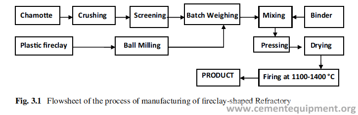
The main raw material used for fireclay Refractories is calcined fireclay or cham-otte, along with plastic fireclay. The flowchart given (Fig. 3.1) shows the manufac-turing process of fireclay Refractories.
Fireclay refractories have alumina and silica as main constituents. The other oxides that remain present as impurities are Fe2O3, CaO, MgO, K2O, and Na2O. All these oxides are acting as flux and bring down the softening temperature of the Refractory. Although the presence of these oxides is undesirable, they cannot be avoided because of their inherent presence in the naturally occurring raw materials. Microstructure analysis of the fireclay refractory reveals that it can contain up to 50% of glassy phase with embedded cristobalite and mullite crystals. The percent-age of glassy phase increases with more fluxes and higher firing temperature. In a fireclay brick with 40% Al2O3, using raw materials with low amount of alkali and fluxes, the share of glassy phase can be reduced to 20% with mullite 55% and cris-tobalite 20–25%. The presence of glassy phase and mullite crystals and their sizes influence the thermo-mechanical behavior of the Refractory. Fireclay Refractories have good volume stability at high temperature, fairly good abrasion resistance, good thermal shock resistance, and very good resistance towards alkali attack at high temperature. Mullite is always a highly desirable phase in fireclay and high alumina refractories.
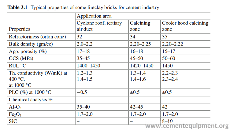
Addition of silicon carbide (SiC) in the fireclay Refractory improves all those properties, to a great extent. In reducing atmosphere, e.g., in CO gas atmosphere, the presence of Fe2O3 catalyzes the decomposition of CO to deposit C in the brick structure, and it becomes fragile because of the expansion associated with the pro-cess. Fireclay Refractories find a wide use in the cement industry in various equipments, e.g., tertiary air duct, cooler, kiln calcining zone, preheater, etc. Typical properties of some fireclay-shaped Refractories used in cement industry are shown in Table 3.1.
High Alumina Refractories
These are categorized as products containing 50–95% Al2O3. Different kinds of raw materials are used in high alumina refractories to achieve the target properties. The major raw materials used are sillimanite, andalusite, raw and calcined kyanite, cal-cined diaspore, calcined bauxite, mullite, brown and white fused alumina, tabular alumina, etc. The Al2O3 content of high alumina Refractories, normally used in cement industry, hardly exceeds 85%. The manufacturing flow sheet is same as that of fireclay Refractory. But there are some qualities which are chemically bonded and do not require any high-temperature firing. The high alumina Refractories can have varied properties depending upon their composition and raw material used. The Refractory composition can be designed to attain particular properties required to perform well in a particular application. Refractories for certain application may demand high thermal shock resistance, and the other application may look for very high abrasion resistance or resistance to alkali attack at high temperature. In all those cases, the Refractory composition and properties will be different. Refractory formulation is done looking to the operational conditions, where the Refractory will be put in.
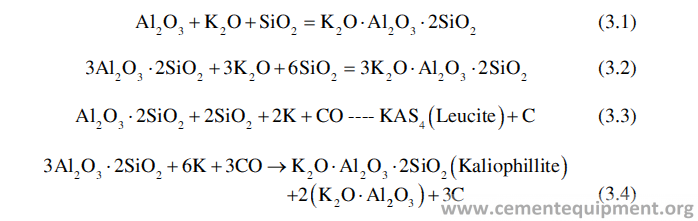
Mullite is one of the most important phases present in the high alumina Refractories, and it is formed by the reaction of alumina and silica at high tempera-ture (above 1100 °C). Mullite is chemically 3Al2O3·2SiO2. It contains 72% Al2O3. The presence of Mullite improves the thermo-mechanical property and the thermal shock resistance of high alumina refractories, and the higher is the Mullite content, the better are those properties. Mullite is also available as a raw material which is made synthetically. The presence of higher percentage of corundum phase increases the abrasion resistance of the high alumina Refractories. The corundum phase is contributed by calcined bauxite, fused alumina, or tabular alumina. High alumina refractories have poor alkali resistance at high temperature. It is found that higher is the alumina content, lesser is the alkali resistance. At high temperature it reacts with alkali oxides to form some felspathic compounds like leucite, kaliophillite, etc. asso-ciated with high volume expansion which completely destroys the Refractory [1–4].
The properties of high alumina Refractories depend upon the raw material base. The andalusite, sillimanite, and kyanite are converted to mullite easily at high tem-perature, and the bricks made out of those raw materials show high thermal shock resistance, high creep resistance at high temperature, and also good alkali resis-tance. Raw kyanite has got the property to expand at high temperature and used to impart a positive PLC in the refractory. The Refractory made out of bauxite shows pyroplasticity (plasticity at higher temperature). By virtue of this property, bauxite- based high alumina Refractories can deform under an applied stress at high tem-perature and can mitigate the effect of the stress. That is how these Refractories show good performance in burning zone of rotary kiln with small to medium diam-eter. High alumina Refractories in general and specially the bauxite-based Refractories show a permanent linear expansion at high temperature, and this helps to keep the lining tight at high temperature during the service. High alumina refrac-tories also are found to take up a stable coating in the burning zone in the cement rotary kiln.
Phosphate-bonded high alumina Refractories show increased resistance to attack by liquid phase in cement clinker and alkali and also have higher abrasion resis-tance. These Refractories are normally fired at lower temperature during manufacturing.
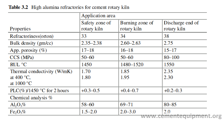
The high alumina Refractories are used for lining various equipments in cement industry. Typical properties of some high alumina-shaped Refractories, used in cement industry, are shown in Table 3.2. In some quality of aluminosilicate Refractories, special ingredients, e.g., SiC (silicon carbide) and ZrSiO3 (zircon), are added to impart special properties like anti-buildup behavior, thermal shock resis-tance, alkali resistance, etc.
Basic Refractory
In earlier days the burning zone of cement rotary kilns was lined with high alumina Refractories. But as the technology has changed over time, from wet to dry process, and the kiln diameter got bigger and bigger, the thermal load on the kiln burning zone increases, and as a result the lining is changed from high alumina to basic.
The main raw material, for all the basic refractories, is dead burnt magnesia (MgO). It can be obtained by high-temperature calcinations of naturally occurring magnesite (MgCO3) above 1700 °C. The processed material is called dead burnt magnesite (DBM), because of its inertness towards hydration. MgO can also be synthesized from seawater [5]. Seawater contains magnesium salts like MgSO4 and MgCl2, which when treated with lime, Mg(OH)2 is precipitated. Mg(OH)2 is then filtered, briquetted, and calcined above 1700 °C to obtain DBM. In another method the magnesite rock is fused by electric arc at very high temperature at about 3000 °C and allowed to cool very slowly when MgO gets crystallized from the melt and forms fused magnesite with large crystals of periclase. It has been found that the properties of basic bricks depend on the properties of the magnesite raw material and source.
The important properties to characterize the magnesia raw material are:
1-Bulk density and grain porosity
2-The impurities and their distribution
3-CaO/SiO2 ratio
4-The boron content
5-The periclase crystal size
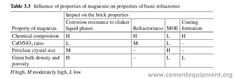
Table 3.3 shows the relation between the properties of magnesite raw material and their influence on the brick properties. The purity of magnesia raw material acts in a different way in the case of natural magnesia and synthetic magnesia [6–8], and a judicious blend of both will be the best. The higher the periclase (MgO) crystal size, the better is the corrosion resistance but lower is the coating formation. The magnesite with higher Fe2O3 is found to have better plasticity etc [9].
Magnesia-Chrome Refractories
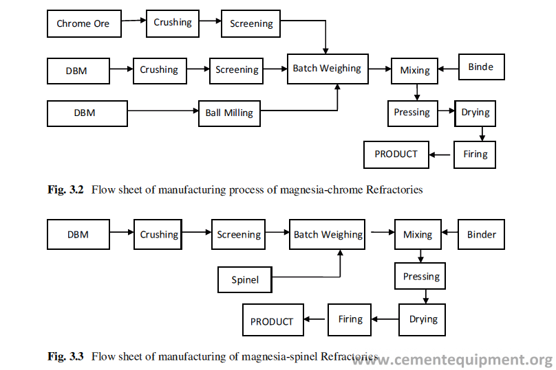
Magnesia-chrome refractory is used mostly in the burning zone of cement rotary kiln. The raw materials used in this product are high purity dead burnt magnesite (DBM) or fused magnesite or their mixture and high-grade chrome ore. The flow sheet of its manufacturing process is shown in Fig. 3.2. The chrome ore contains MgO.Cr2O3 and FeO.Cr2O3 spinels.
Addition of chrome ore reduces the modulus of elasticity [10] and improves the thermal shock resistance of magnesia Refractory and its resistance to acidic slag. Magnesia-chrome Refractories are found to form a good coating of clinker on the brick-lining surface in cement rotary kiln, which protects the brick lining from high temperature and thermal shock and enhances the campaign life. But many countries have put a ban on the use of magnesia-chrome Refractories because of environmen-tal pollution, caused by the disposal of the used magnesia chromite brick lining. The Cr2O3 in the refractory reacts with alkalis at high temperature, during its use, to form water-soluble hexavalent chrome containing alkali chromate salts, which are carcinogenic in nature. The rainwater can leach out the Cr+6 and can pollute the groundwater reserve causing health hazards. The typical properties of this product are shown in Table 3.5.
Magnesia-Alumina Spinel
Magnesia-alumina spinel Refractory is used in both transition zones and burning zone of cement rotary kiln [11]. The main raw materials for this product are high purity dead burnt magnesite and spinel. Spinel is a mineral phase having a chemical formula MgO·Al2O3. Spinel is not available in nature and is made synthetically by high-tem-perature reaction between magnesia and alumina. The spinel has got a general formula AB2O4, where A = divalent atom and B = trivalent atom. Other mineral phases, having similar crystal structure as spinel, used in basic refractories for rotary kiln lining, are hercynite (FeAl2O4), galaxite (MnAl2O4), and pleonaste (Mg-Fe-Al spinel) [12].
Addition of spinel reduces the modulus of elasticity of magnesia Refractories and makes it more flexible to withstand thermo-mechanical stresses. The flow sheet for manufacturing magnesia-spinel Refractory product is given in Fig. 3.3. The spinel can be added as preformed spinel, or it can be formed in situ or as a combination.
TiO2 is added as catalyst for spinel formation at lower temperature [13]. TiO2 also improves the coating forming ability of Spinel containing refractory. Addition of SnO2 is found to improve the thermodynamic stability of Al2O3- MgO Spinel [13].
This product has got very high thermal shock resistance and performs very well in transition zone lining where the coating formation is less and the thermal shock is very high. It has also got a very high resistance to alkali attack and corrosion towards the cement liquid phase at high temperature. The typical properties of this product are given in Table 3.5.
Magnesia Hercynite
Magnesia hercynite Refractory is made from DBM and hercynite. Hercynite is a synthetic mineral with spinel structure having a formula of FeO·Al2O3. Addition of hercynite to magnesia refractories reduces its modulus of elasticity and enhances flexibility. It also reduces brittleness of magnesia Refractories towards thermo- mechanical stresses. The magnesia hercynite Refractory has good ability to take up the clinker coating, and all the said properties have made it a suitable candidate for burning zone lining of cement rotary kiln. It has also got a very high resistance to alkali attack and corrosion towards the cement liquid phase. It has the added advan-tage of being free from Cr2O3 and therefore more environment friendly by nature. The flow sheet of manufacturing of this Refractory is similar to magnesia spinel Refractory. The typical property of such Refractory is given in Table 3.5.
The spinels have lower thermal expansion than the periclase (MgO). As a part of the manufacturing process, these brick are fired at high temperature (1580–1650 °C). Due to mismatch of thermal expansion behavior, microcracks are developed in the refractory microstructure, surrounding the spinel grains, which makes the Refractory more flexible and improves its capability to withstand more thermo-mechanical stresses.
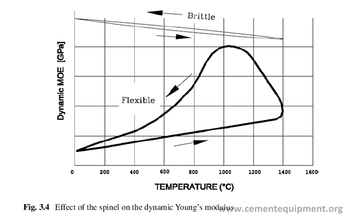
Figure 3.4 shows the typical thermo-mechanical behavior of a magnesia brick without spinel and a magnesia brick containing a spinel [14, 15]. A pure magnesia brick shows an almost constant Young’s moduli at a high level, but with the inclu-sion of spinel, the Young’s modulus starts at a low level, increases slowly during heating, and shows rapid increase in the first stage of cooling to 1000 °C. The flexi-bilization effect occurs during cooling at temperature below 1000 °C, and the Young’s modulus is lowered significantly. The Young’s modulus level provides an indication of the ability of an additive to flexibilize or elastify a magnesia brick. Spinels are also called as elastifiers, when added to basic refractories [16–21].
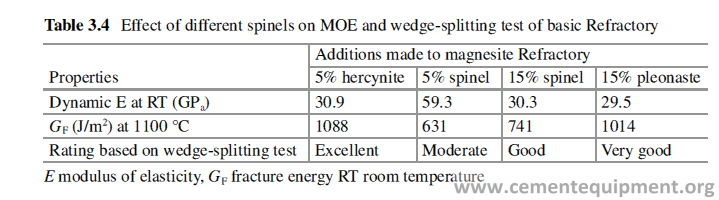
The effect of addition of different kinds of spinels on the basic Refractory [14] is shown in Table 3.4, and it is clearly evident that the fracture toughness has been increased significantly by addition of the spinels. It has also been found that forster-ite (MgO·SiO2) phase, developed in the basic bricks, can also act as an elastifier [22]. But the chemistry and the microstructure of the brick are to be engineered properly to get the best effect.
Magnesia Zirconia
Magnesia-zirconia Refractory is made out of high purity dead-burnt magnesia or fused magnesia and monoclinic or stabilized zirconia [23–25]. This Refractory body contains periclase and stabilized zirconium oxide (ZrO2) or calcium zirconate (CaZrO3). Uniform distribution of ZrO2 in the brick structure improves thermal shock resistance due to microcrack formation. During the partial or total stabiliza-tion of ZrO2, diffusion takes place between MgO and ZrO2, and this helps to form direct bond and increases the hot strength which helps to withstand the mechanical stress at high temperature. Magnesia-zirconia bricks have high corrosion resistance against alkali and against basic slag at high temperature. The addition of ZrO2 in Magnesia Spinel bricks has been found to improve both coating formation and cor-rosion resistance [26]. The simultaneous addition of MgAl2O4 and CaZrO3 to small volume percentage (4%) is reported to improve its corrosion resistance and its coat-ing property [27]. The flow sheet of manufacturing is the same as magnesia spinel brick. Typical property of magnesia-zirconia brick is shown in Table 3.5.
Dolomite
Dolomite Refractory is made out of naturally occurring dolomite which is a solid solution of MgCO3 and CaCO3. The pure grade of dolomite is calcined at very high temperature to reduce its affinity to react with atmospheric moisture and to make itstable. The dead burnt dolomite is the basic raw material for manufacturing the dolomite Refractories. There are a number of unique properties in dolomite brick that make it well suited for use as a Refractory lining for burning zone of a cement rotary kiln [28, 29]. A high degree of refractoriness allows the dolomite brick to withstand the temperature and involved stress in the burning zone. The corrosion resistance to alkalis and a reducing atmosphere, as well as excellent ability for coat-ing formation, make it a good candidate for the lining of burning zone of cement rotary kiln. A good coating formation is the most important property of a basic brick. In practice, a coating will form if the conditions in the kiln are appropriate. The biggest difference between different types of bricks used in this context is how well they will hold onto the coating, once it is formed.
In practice, the clinker coating on the refractory lining is not always present dur-ing campaign of the lining. Some or all coating loss may be caused by thermal shock. When the coating on the lining is destabilized, the brick underneath is sub-ject to a sudden temperature change, which will expose the brick to severe thermal shock. For a long period of time, standard dolomite was limited to the area where stable coating existed over the refractory lining, and shutdowns were minimal.
However, the thermal shock resistance of the dolomite brick has been improved significantly by the development of zirconia-enriched dolomite refractories [25, 29]. Zirconia was chosen because it is relatively nonreactive with dolomite, and addition of special grade of Zirconia imparts high thermal shock resistance. Finally, the environmental safety of the used dolomite bricks is outstanding. One of the greatest disadvantages of dolomite Refractory is its susceptibility to react with atmospheric moisture. The process is called hydration, in which the CaO of dolo-mite reacts with water vapor to form Ca(OH)2 and causes destruction of the brick lining. In coating-free area, dolomite reacts with kiln gases to form CaCO3, CaSO4, or CaS [30, 31].
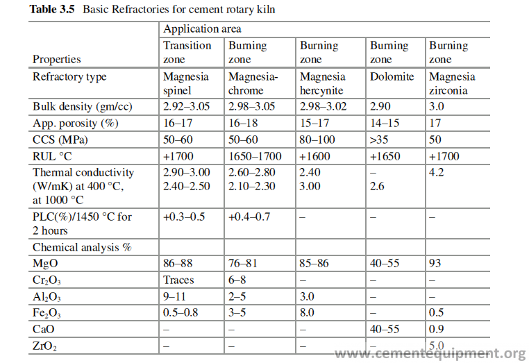
The phenomenon is more prominent in tropical countries with high level of humidity. Table 3.5 furnishes the typical properties and specification of dolomite Refractories.
Unshaped Refractories
Various types of unshaped Refractories are available for different applications in different industries. These includes castables, ramming masses, plastics, and mor-tars. Out of all these, castables and mortars are the main types of unshaped Refractories used in the different applications across the cement industry. Castables can be of different types, meant for different applications. Castables are basically a dry mixture of Refractory aggregates, calcium aluminate cement [32, 33], and some small but very important additives. The Refractory aggregates can be chamotte, andalusite, sillimanite, calcined diaspore, calcined bauxite, brown fused alumina, white fused alumina, tabular alumina, silicon carbide, etc. of different sizes, varying normally from 10 mm to superfine material. The different ingredients in different sizes and in different proportion as per the design of the formulation are mixed together along with high alumina cement as binder to make the castable ready for packing and dispatch.
Castable
The castables can be applied in different ways like pouring, vibration casting, gun-ning, shotcreting, ramming, troweling, etc [34]. Depending upon the place of appli-cation and method of application of the castable, the aggregate quality and the percentages and quality of calcium aluminate cement and additives are decided to engineer its rheology or flow property, to make it suitable for a particular applica-tion method mentioned before [35].
The most important properties of castable, which are ignored sometimes by the manufacturer, are its properties related to installation, e.g., flow property, duration it remains workable, setting time, scope of installation method and preheating arrange-ments available. If the installation is sound, half of the battle is won. Many a times desired campaign life is not obtained, because of improper installation. If the prop-erties mentioned before, necessary for a good quality of installation, do not match with the actual properties of the castable, the installation quality will not be sound, and it will not perform well. The supplier must design the castable recipe taking into consideration the installation method to be employed and the operational condition that prevails (e.g., ambient temperature, etc.). Similarly, during the installation of the castable, the installer should have prior knowledge of the earlier mentioned properties of the castable required for sound installation. The same castable, when installed in a country in Europe in winter and in a country in the Middle East in summer, will not behave similarly because of different ambient conditions. Both the manufacturer of the castable and the user must bear this in mind during manufactur-ing and installation of castable refractories, and proper attention should be paid.
Castables can be installed by different methods, e.g., by pouring, by vibration casting, by gunning, and by shotcreting. Two major steps in the installation pro-cesses are mixing of castables with water and the method of consolidation of the castable. Mixing quality is very important, and the aim should be to get maximum flow using the prescribed water or binder content. That is possible only when the mixing is very thorough and intimate, done in high shear mix.
The general flow sheet for manufacturing of castable is given in Fig. 3.5. The characteristics of different types of castables are discussed below.
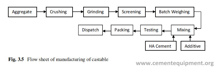
Conventional Castable
This is a mixture of Refractory aggregates with 15–25% high alumina cement. These castables are required to mix with prescribed quantity of water and either cast, poured, or rammed. In castable the aggregates used are normally aluminosili-cate type, but in some special cases, SiC or zircon is also used. Conventional casta-bles can be rammed, vibrocast, or poured. These are also good materials for patching by troweling.
The special feature of these castables is the loss of strength, with rise of tempera-ture, till it reaches a minimum value at a temperature range 800–1000 °C and then there is a rise of strength with increased temperature. The initial loss of strength with rise of temperature is because of the disintegration of the hydraulic bond formed, and later the increase of strength is due to sintering process. Typical speci-fication of this type of castables used in cement plant is given in Table 3.6.
Low Cement Castable (LCC)
This is a mixture of Refractory aggregates and 5–8% high alumina cement with other minor, but very important, additives which helps to get the desired flow prop-erty and enables installation by vibration casting with much lower water percent. Good flow property of the castable mix with low water content ensures better pack-ing lower porosity higher mechanical strength and high volume stability at elevated temperature. The low cement castable should always be mixed with water in mechanical mixer and is to be installed by vibration casting. Ordinary mixing with water does not develop the desired flow property in the mix, and vibration casting with low water content is not possible. Addition of higher percentage of water will be disastrous and will impair setting and strength of the castable.
Ultra-low Cement Castable (ULCC)
These products are very similar to the low cement castables except further lower content (2–4%) of high alumina cement. Its features are similar to that of the LCC, but the high-temperature tensile strength is better than that of LCC with similar Al2O3 content because of lower flux content (CaO) due to the lower content of high alumina cement.
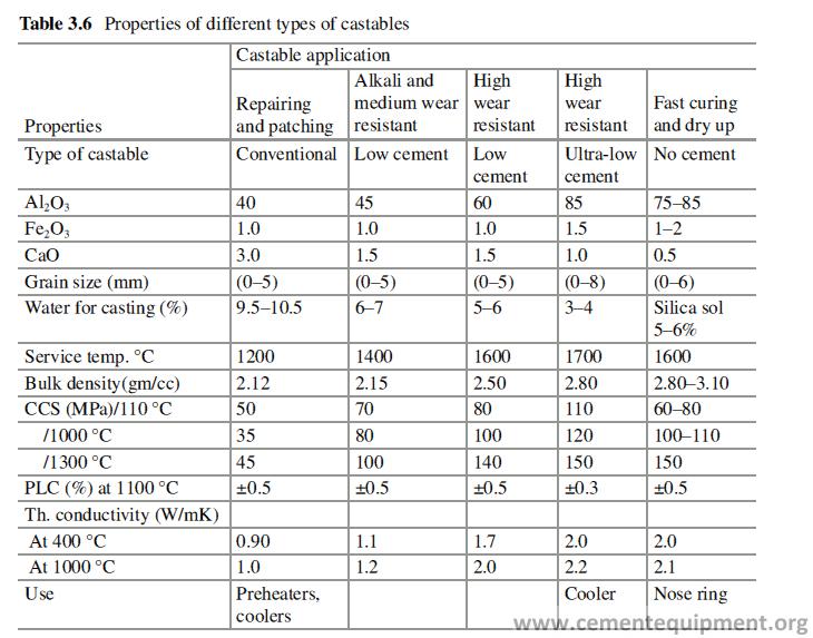
The very important differences in the behavior of the low cement and ultra-low cement castables from that of conventional castables are:
Obtaining required rheological property with addition of much lower amount of water, compared to conventional castable.
Increased strength with increasing temperature (Fig. 3.6).
Having higher density, lower permeability, and high sensitivity to method of pre-heating because of the low water requirement for casting. Faster preheating may lead to explosive spalling and crack in the body, although the addition of special additives reduces its sensitivity towards heating rate.
No Cement Castable (NCC)
In these products silica or alumina sols are used as binders, and a gelling agent (high alumina cement up to 1%) is used to set the castable.
These products are mostly two-pack products. Refractory aggregates are supplied loose in bags, and the binder liquid (silica sol) is supplied in drum. The two compo-nents are mixed at site and are cast. But recently the solid powder is developed which forms sol when added to water, and one pack product of no cement castable can be produced using that binder. The special features of these products are:
- These products are to be applied by vibration casting.
- The strength increases with temperature.
- These can be preheated at a much faster rate compared to the cement-bonded castables (Fig. 7), and therefore total preheating time is much less which is a major advantage of chemically bonded castable [36].Recommendations for mixer type, mixing time, and application methods for dif- ferent types of castables are given in Table 3.7.
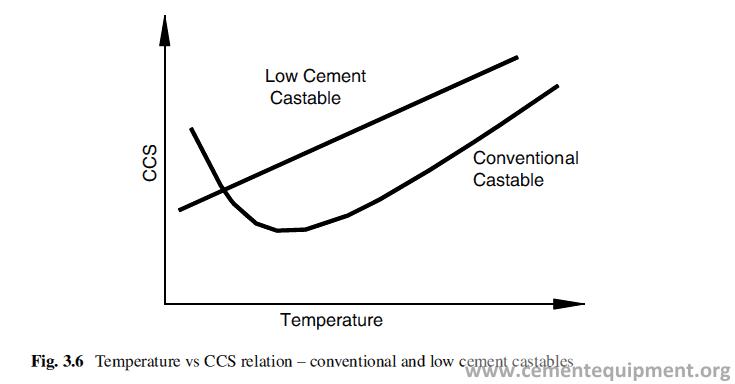
Gunning Mass
Gunning mass is supplied in powder form, and it is made out of aluminosilicate raw material and calcium aluminate cement mixed with other additives [37]. Gunning machine is used to spray the material on the place of installation. After charging the material in the hopper of the gunning machine, the material is transported through a long rubber hose, connected to a steel nozzle at the other end, by pneumatic pres-sure. The gunning material is mixed with water at the junction of rubber hose and steel nozzle, through a separately connected pipe, and ultimately sprayed on the application area.
It is used for both installation of new lining and for repairing a worn-out lining. Gunning installation is a very specialized job, and the quality of the installation depends largely on the skill of the operator (gunman).
Portion of the gunning material sprayed, rebounds from the target wall and falls down and is called rebound loss. The lesser is the rebound loss, the better is the quality of gunning. The rebound loss depends upon the material quality, the water percentage used for gunning (controlled by operator), distance of the Gunning noz-zle from the target surface, and the angle of nozzle with the wall to be gunned.
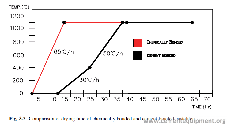
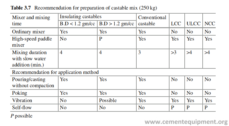
Shotcrete and Pumpable Material
Shotcreting is normally done in an installation where large quantity of Refractory needs to be installed. It is very convenient to use this process when the installation is to be done at a height, for example, in preheater cyclone. In shotcrete installation, the shotcrete machine is kept at ground level. The castable material is mixed with recommended amount of water in the shotcrete machine to make slurry, and the slurry is then pumped through the rubber hose to the installation point and is sprayed on the target surface by compressed air. Before the material comes out through the nozzle, a setting agent is mixed with the slurry to accelerate the setting. The rheological property of shotcrete is very important towards its successful use. The differences in the installation process of castables by gunning and shotcreting are given in Table 3.8.
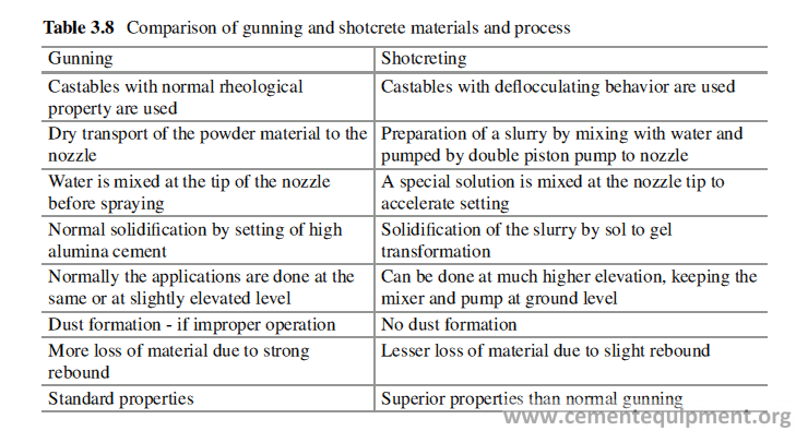
As it was discussed in Sect. 3.3.1, basically, the castable with the same chemical specification can be modified to install by different methods, e.g., by pumping the slurry, by self-flow technique, by gunning or shotcreting, depending upon the demand of the user. The basic ingredients of the castable remain the same, but the rheological or flow property is modified by addition of small amounts of additives [38] and control of particle size to achieve the desired flow property as the selected installation method demands. The properties of 50% alumina castable installed by different methods described are given in Table 3.9.
Ramming Mass
This is a combination of Refractory aggregates and some additives as binders. It is supplied in powder form. The powder mass is mixed with prescribed quantity of water or any other specified liquid binder to get a semidry consistency and then installed by pneumatic ramming or by hand ramming. These products are recom-mended for small repair jobs or to fill up some cavity or gaps, in the new brick-lined construction in cement plant application. Typical property of a Ramming mass is shown in Table 3.10.
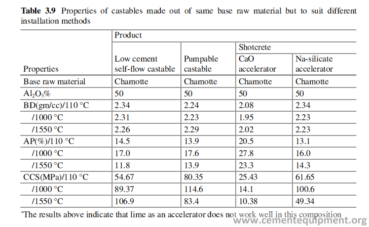
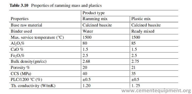
Plastic
This is manufactured and supplied in ready to use form, in small blocks, wrapped in polythene packet with stiff mud consistency. It is to be unpacked and to be installed either by ramming or tamping in the place of application. This is normally available in aluminosilicate range. The advantages of this product are it is available in ready condi-tion saves time. Quality consistency of the installed refractory lining is ensured because the water or the binder need not to be added at site. It gets set and hardened when it gets temperature. The preheating of this product can be done at a much faster rate compared to castables. Typical property of a plastic material is shown in Table 3.10.
Mortar
Mortars are used to join the bricks in the refractory lining. Mortars used to have almost similar chemical composition as the bricks to be joined. Mortars are gener-ally supplied as dry powder which is to be mixed with water or other specified liquid binders to form a paste which is trowelable and can be spread over the brick surface to act as glue to fix another brick. The mortars can be heat set, air set, or chemical set, depending upon the development of strength of the mortar on heating or in the presence of air or by its own. The heat-set mortars develop their strength after heat-ing the lining, whereas the chemically set or air-set mortars develop their strength at ambient temperature itself, by chemical reaction. The mortar should have the prop-erty of good workability when mixed with water and should not get dried up fast, because of absorption of water in the brick pores, when applied on a brick surface.
Insulation Refractory
Cement industry is an energy-intensive industry. Consumption of more energy is uneconomic, and it has got a negative impact on the environment for liberation of more greenhouse gases. Because of this reason, the use of insulation refractory in cement industry is becoming more and more important. The thermal insulation can be provided by both shaped and unshaped refractories. The insulation refractories have high porosity, low strength, and low abrasion resistance, and due to this reason, the insulation refractories are used always as backup lining. The different insulation materials have different properties and have different applications. The different types of insulation refractories are classified in different groups according to the ASTM standard as given in Table 3.11. The classification is based on the bulk den-sity and the reheat change of the brick.
The main features of the insulating refractories are high porosity and low bulk density. The pores are deliberately created in insulating refractories to entrap air, which provide very good thermal insulation and impart low thermal conductivity to the body.
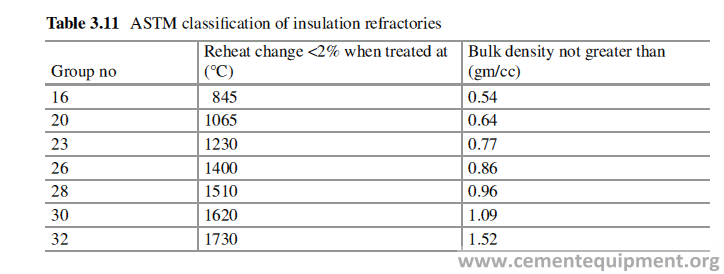
All the thermal-insulating materials are basically oxides, because compounds other than oxides have innate higher thermal conductivity. The service temperature of insulating refractory and its volume stability at that temperature is also important to design a refractory lining.
Insulation Shapes
Insulation refractory shapes can be manufactured from porous raw material, e.g., molar clay or exfoliated vermiculite, or from fireclay by introducing some organic combustibles in the mix which leave behind the pores on burnout. The properties of the fireclay insulation bricks are given in Table 3.12.
Calcium Silicate
This is available as boards of 25, 50, and 100 mm thickness and with different length and breadth. Calcium silicates are very light and efficient thermal-insulating material and are used in large quantity in cement industries. They are produced synthetically by hydrothermal reaction between lime and silica. The calcium sili-cate blocks are available in two different grades suitable for application tempera-tures up to 800 and 1100 °C. The thermal stability is based on the amount of calcium
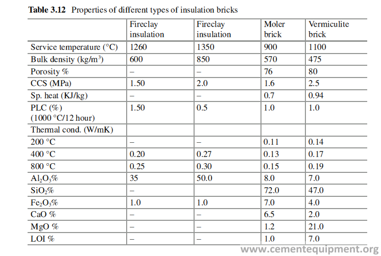
silicate hydrate shares (tobermorite 5CaO·6SiO2·5H2O and xonotlite 6CaO·6SiO2·H2O), due to their different shrinkage behavior and removal of bonded water. The calcium silicate blocks can be sawed and drilled as per the need. The properties of these materials are given in Table 3.13. Calcium silicate insulation blocks can be used as backup lining for both brick lining and for castable lining.
Ceramic Fiber Products
Ceramic blanket and ceramic papers are used widely as insulation material in dif-ferent equipments during the refractory lining. These products are made from ceramic fibers.
Ceramic fibers are manufactured by melting aluminosilicate material at very high temperature in electric arc furnace, and the pouring stream of the melt is blown at, by jet of high pressure steam, when the molten aluminosilicate material will form fluffy fibrous material. These fibers are woven or processed to form ceramic blan-ket, ceramic papers, and ropes. The products are available with different grades according to the service temperature, density, and shrinkage value. The character and properties of these products are shown in Table 3.14.
Insulation Castable
Insulating castables are made from porous refractory aggregates and mixed with calcium aluminate cement as binder. The content of high alumina cement used in insulating castables is normally much higher than dense castables to get the desired
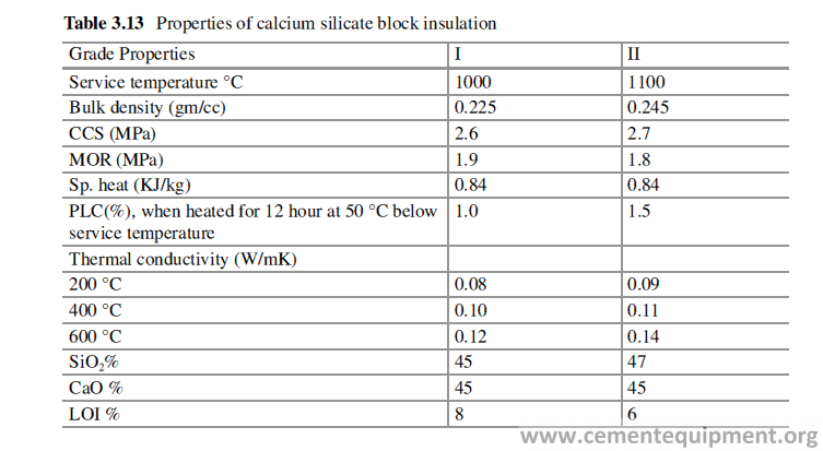
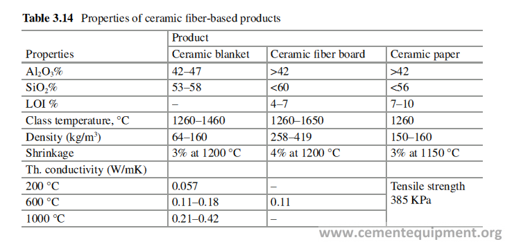
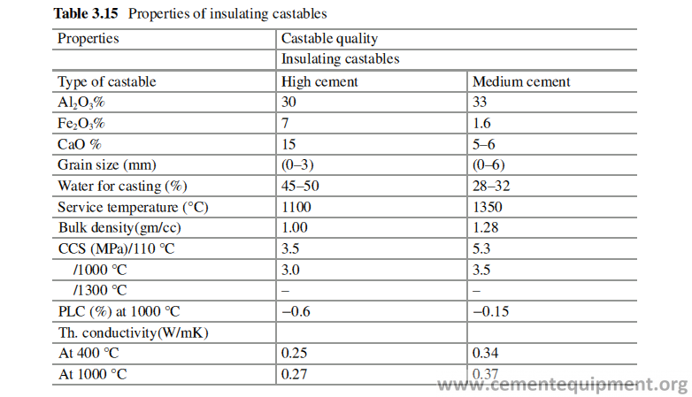
mechanical strength. The insulating property of the castable depends upon the type of aggregate used and the composition of the castable. The properties of the insulat-ing castables are shown in Table 3.15. Insulating castables require much higher percentage of water to attain the consistency required for its placement.
Cement Manufacturing and Process Control
Cement Manufacturing: Basic Process and Operation
To design the Refractory for the lining of different equipments in a cement plant, it is necessary to understand the total operational process of a cement plant in depth. It is necessary to know the conditions prevailing in different equipments and the physical and chemical parameters the Refractories will be exposed to during opera-tion. The physical parameters are temperature, pressure, air velocity, abrasion, mechanical stress, content of liquid phase generated at the operating temperature, liquid viscosity, surface tension, etc., and the chemical factors include chemistry of solid, liquid, and gas in contact with the Refractory. Once these information are available, the right kind of Refractories, which can withstand best under those con-ditions, can be designed.
The common raw materials used for manufacturing of cement include limestone, shell, and chalk or marl combined with shale, clay, slate, blast furnace slag, silica sand, and iron ore. These ingredients, when heated at high temperatures, form a rock-like substance that is ground into the fine powder that we commonly call as cement.
The early manufacturing process of cement was through wet process, in which slurry, made of ground raw material and water, used to feed the rotary kiln. But this process requires a high amount of energy, mainly to evaporate the water in the slurry and become uneconomic and largely abandoned. The energy requirement to pro-duce cement in dry route is approximately half of the energy required to produce it through the wet process.
The most common way to manufacture Portland cement is through a dry process. The first step is to quarry the principal raw materials, mainly limestone, clay, and other materials. After quarrying, the rock is crushed. This involves several stages. First, crushing reduces the rocks to a maximum size of about 6 inches. The rocks then go to secondary crushers or hammer mills for reduction to about 3 inches or smaller. The crushed rocks are combined with other ingredients, such as iron ore or fly ash, and are ground, mixed, and fed to the cement kiln.
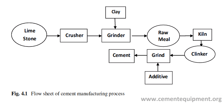
In the cement kiln, all the ingredients are heated to about 1400–1500 °C in huge horizontal cylindrical steel tubular vessel called rotary kiln, lined inside with special Refractory material. Kilns are as much as 3–7 m in diameter and about 60–75 m in length. The kilns are mounted on two or three supports with the axis, inclined slightly from the horizontal. The finely ground raw material is fed into the higher end. The lower end is fitted with a concentric burner producing a strong flame, by controlled burning of powdered coal, oil, alternative fuels, or gas under forced draft. As the material moves through the kiln, the materials react among themselves at high temperature and form a new substance called clinker. Clinker comes out of the kiln as dark gray balls, about the size of 0–50 mm.
Clinker is discharged red-hot from the lower end of the kiln and generally is brought down to handling temperature in various types of coolers. The heated air from the coolers is returned to the kilns, a process that saves fuel and increases burn-ing efficiency.
After the clinker is cooled, it is ground and mixed with small amounts of gypsum and limestone. The cement is now ready for use in construction projects. The flow sheet of cement manufacturing is given in Fig. 4.1. Kiln feed is subjected to succes-sive physical and chemical reactions as its temperature rises gradually as shown in Table 4.1.
Raw Material
The major raw materials used as a source of CaO for cement manufacturing are limestone, chalk, marl, etc. These raw materials by virtue of their natural occurrence contains other mineral impurities e.g, MgO, SiO2, Al2O3, Fe2O3, alkali compounds, and sulfides. These impurities play an important role to influence the cement manu-facturing process as well as Refractory performance. Similarly, as a source of SiO2, clay minerals and shale are used, which also contain similar kind of impurities and affect the performance of Refractory.
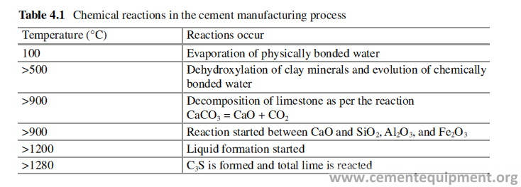
Fuel
Different fuels like coal, oil, petcoke, gas, etc. are used as the source of heat energy to carry out the reactions inside the cement rotary kiln. The fuel cost is about 50% of the total energy cost and 10% of the total cost for cement production. Therefore a continuous effort is going around the globe in search of cheaper source of fuels. As a result, a lot of other fuels are being found and used more and more to replace the conventional fuels, and these are called alternate fuels. The cement kilns are being used in developed countries as an incinerator, and all kinds of industrial and domestic wastes are used as source of energy. The common alternate fuels used are petroleum coke, shredded tires, plastics, waste oil and solvents, animal meat, bones and fats, municipal wastes, agricultural wastes, etc. Some of these materials contain high percent of alkali, sulfur and chlorine, for which some special cares are to be taken in the manufacturing processes to maintain smooth operation and these impu-rities again affect the Refractory performances to a great extent. The acidic gases, formed because of burning of alternate fuels, permeate through the Refractory and corrode the kiln shell and anchors which hold the monolithic lining.
Different Plant Design
Energy is the major cost in clinker manufacturing process. The energy means the combination of thermal energy from the fuel and the electrical energy required to rotate the kiln and to run the cooler and the number of ID fans.
In the cement plant, the preheater system functions as heat exchanger. The hot gas generated in the kiln to burn the clinker leaves the kiln and moves up the pre-heater to heat up the raw meal falling vertically through the preheater system. The thermal energy cost of the cement manufacturing depends upon the heat exchange efficiency of the system. The electrical energy requirement depends on the kiln length, the electrical power of the ID fans, and the electrical power used to run the cooler.
The different kiln system designs are developed over the years to improve the energy efficiency and to take care of ever-increasing capacity of the cement plants. The feature and advantages of different designs are discussed here [1–3].
Suspension Preheater (SP) Kiln
This system is suitable for plant with capacity up to 4500 TPD of clinker. It has low specific power consumption and simple operation and is well suited for manual control. The extent of calcination at the kiln inlet is 30–40%. This process can accept higher input of chlorides than pre-calcining system with tertiary air duct (without bypass). The ratio of firing in riser duct is 0–15%.
Line Calciner Using Excess Air
It is suitable for plant with capacity up to 5500 TPD clinker. Ratio of firing in cal-ciner is 10–25%, and the calcination at the kiln inlet is 50–70%. The advantage of this system is low coating tendency in kiln inlet and riser duct. The coating in burn-ing zone is stable, and it is less sensitive to chloride and sulfur. The kiln dimension is smaller than SP system.
In-Line Calciner (ILC)
In this system the capacity can be made up to 6000 TPD and with multiple strings up to 10,000 TPD clinker. High material and gas retention time is obtained in cal-ciner due to its large volume and moderate swirl. Ratio of firing in calciner is 55–65%, and calcination at kiln inlet is 90–95%. Bypass of kiln gas is 0–100%. This system is well suited for low-grade fuels. Refractory life is long because of low thermal loading and stable coating.
Separate Line Calciner Downdraft (SLC-D)
Normal capacity is up to 6000 TPD and up to 10,000 TPD with multiple strings. Firing in calciner is 55–65% and calcination at the kiln inlet is 90–95%. The pro-cess is very well suited for all types of fuel, especially low volatile fuels. The combustion in the calciner takes place in hot atmospheric air, and the combustion temperature can be controlled independently of the temperature of the calcined material which is fed to the kiln. Low NOX operation is possible in this design.
The tower dimension can be made smaller as it can be installed separately from the cyclone tower.
Separate Line Calciner (SLC)
With this system the normal capacity can be up to 7000 TPD clinker, and with two strings it can go up to 12,000 TPD. The firing in calciner is 55–60%, and the calcination at the kiln outlet is 90–95%. The other features are very similar to SLC-D system.
Separate Line Calciner with In-Line Calciner (SLC-I)
With this system normal capacity can be up to 11,000 TPD clinker. Firing in kiln string ILC is 10–15% and in calciner string SLC is 40–50%. Calcination at the kiln inlet is 90–95%. Long refractory life is obtained due to low thermal kiln load and stable coating. Other features are same as SLC system.
The ILC-I and SLC kiln systems allow bypassing up to 100% of the kiln gas, while the other kiln systems can be equipped with a bypass carrying a maximum 25–60% of the kiln gas, which in most cases will suffice to ensure smooth opera-tion, even with low-grade raw materials.
Figure 4.2 shows the typical temperature and pressure profile of the cyclone preheater system.
In the SLC configuration, the hot tertiary air from the cooler enters the calciner through the central inlet in the bottom cone and leaves through either a side outlet or through an outlet cone connected to a central outlet pipe. In the SLC-I configura-tion, a SLC calciner is built parallel to the kiln riser duct, and a second ILC calciner is built into the kiln riser duct. A unique feature of the high-temperature calciner system is the fact that the temperature inside the calciner is independently con-trolled by the position of the gate that divides the raw meal flow to the calciner and to the kiln riser duct, respectively. So, by feeding a relatively larger amount of raw meal to the kiln riser duct and keeping the fuel input to the calciner constant, the mean temperature in the calciner vessel can be brought up to 950–1050 °C. The temperature of the exit gas and the degree of calcination of the raw meal leaving the calciner will increase accordingly. However, when mixing with the kiln exhaust gas that contains uncalcined raw meal, the temperature of the gas/particle suspension falls to approximately 900 °C. So a normal temperature level is maintained in the calciner cyclone. Similarly, a normal degree of calcination of 90–95% is maintained for the raw meal supplied to the kiln. The higher temperature in the calciner ensures effective combustion of even low reactive fuels and helps to greatly minimize fuel NOx formation. The calciners of the SLC and SLC-I systems are characterized by a vortex formation in the bottom cone, ensuring effective mixing of raw meal, fuel, and tertiary air for a high particle-to-gas retention time ratio.
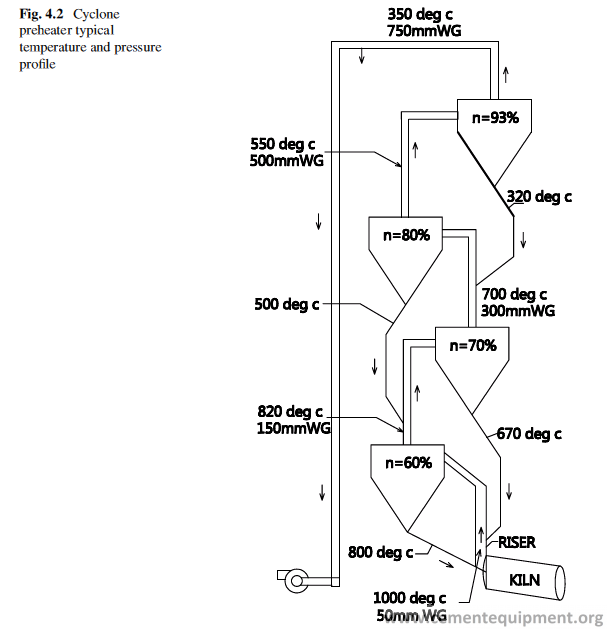
Rotary Kiln
The rotary kiln is the heart of the cement plant. The raw meal, which is a mixture of finely ground limestone and clay or shale, is fed to the system at the top of the pre-heater tower. The material flows down to kiln. In the kiln the solid-state reaction occurs between the CaO, SiO2, Al2O3, and Fe2O3 to produce the liquid phase required for nodulization of clinker and formation of different mineral phases like C3S, C2S, etc. The kiln operation is monitored by several physical parameters as given below:
(a) Production rate, tons per hour clinker
(b) Operating hours
(c) Involuntary downtime hours
(d) Total fuel rate, tons per hour
(e) Proportion of fuel in pre-calciner/riser
(f) Specific heat consumption, kcal/kg
(g) Secondary air temperature
(h) Kiln feed end temperature
(i) Preheater gas exhaust temperature
(j) ID fan draft in mm of water column
(k) Kiln feed end oxygen
(l) Downcomer oxygen
(m) Kiln feed end material, loss on Ignition (LOI), and SO3
(n) Kiln drive power
(o) Specific kiln volume loading %
(p) Specific heat loading of burning zone, kcal/h/m2
(q) Temperature, pressure, and oxygen profile of preheater
Kiln Control Parameters
The measured values of those parameters that are the most important for kiln opera-tion are herein called the control parameters. To keep the control parameters close to a certain target, control variables (or actuators) are manipulated. These parame-ters have immense effect on the refractory performance. During any prematured refractory life, these parameters help to analyze what kind of stresses the refracto-ries were loaded to. For example, if the burning zone temperature exceeds the norm, the Refractory in burning zone is definitely thermally overstressed. The measure-ments of parameters like increase in NOx or the change in torque of the kiln give an indirect indication of increased burning zone temperature (BZT).
The most important control parameters that are looked at during operation of any type of kiln system are:
- Burning zone temperature (BZT) as an indicator for the produced clinker quality.
- Back-end temperature (BET), as an indicator for the raw meal preparation, which is mainly the degree of drying, heat up, and calcinations
- Oxygen concentration of the kiln exit gas (as an indicator for the efficiency of combustion)
- In case of pre-calciner systems: temperature and oxygen concentration at pre- calciner outlet
- In case of grate cooler: bed height of the clinker layer on the grate
The location where the different control parameters are measured and some typical target values are given below. The control variables, which are adjusted, to keep the parameter close to target, are shown for preheater and pre-calciner kiln design (Figs. 4.3 and 4.4). The most important control parameters that are looked at during kiln operation are:
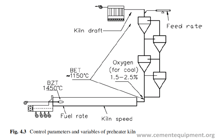
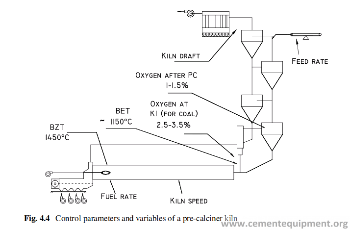
Burning Zone Temperature (BZT)
The BZT determines how well the clinker is burned and how complete the transfor-mation from C2S to C3S is. When the clinker is leaving the burning zone, it should not have more than ~1.5% and not less than ~0.5% of uncombined CaO or free lime (which roughly corresponds to a liter weight of about 1250–1350 g/l). The periodi-cally measured free CaO is the main indicator to state, if the actual BZT target is adequate or it needs to be made higher or lower. Due to changes of the raw meal composition, an alteration of the BZT target can be required often, since burnability of the raw material changes with fluctuations of the LSF, SR, magnesia, and alkali content among other factors. A change in the flame characteristics, which can result from the use of multiple fuels or varying combustion conditions, has a similar impact and therefore may also require an alteration of the BZT target.
Variations of the BZT target are made only over a long-term period, and the actual BZT must be measured to determine, if a deviation between the temporary target and the actual BZT exists. Since kiln operation is a dynamic process, devia-tions are quite frequent and of a short-term character. Several indicators are used to determine the BZT, and they are listed next. Most of them do not explicitly express an absolute temperature, but they give sufficient information to establish, if the BZT is increased or decreased compared to an earlier defined target. This means they give the short-term trend of the control parameter BZT.
Pyrometer
Any hot body emits a radiation which is related to its temperature. The color and the intensity of the radiation depend on its temperature (Table 4.2). An optical tempera-ture can be used to measure the temperature by matching the color of a glowing filament against the radiation emitted by a hot body.
NOx
The NOx produced during combustion varies according to the temperature of the flame and of the gases of the burning zone. The hotter is the flame more NOx is produced during combustion and vice versa.
When BZT is deduced from the NOx content of the exhaust gases, the oxygen and CO concentration in the exhaust gases have to be considered also, since CO reduces and oxygen promotes the formation of NOx. A further factor influencing NOx formation is the type of fuel burned. If the fuel mix changes, the quantity of NOx produced may change too (especially when burning alternative fuels).
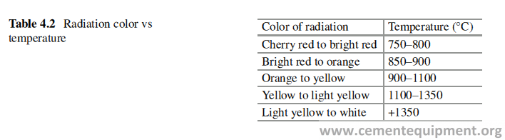
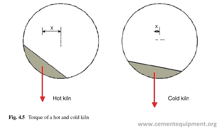
Kiln Torque
A higher burning zone temperature produces more liquid phase in the clinker, and if BZT rises, the burning zone gets longer and shifts upwards. The diameter of the clinker balls increases, and the granulation of the raw meal in the kiln starts earlier. Therefore more and bigger clinker balls have to be moved inside the kiln when the BZT is increasing. At the same time, the material bed in the kiln is lifted up more, which moves the center of gravity away from the kiln axis (Fig. 4.5). The different granulation of the clinker and the changing angle of repose increase the required torque to turn the kiln, if BZT rises.
A changing coating situation in the burning zone strongly influences the kiln torque (as more as lower the L/D ratio of the kiln). As a result the kiln torque can change significantly on a long-term basis without any change of the BZT. Therefore the kiln torque signal in most cases only serves as a short-term indication of the BZT. Short term is defined as up to 12 h. Torque is a very useful indicator of kiln conditions relative to its trend.
Secondary Air Temperature (SAT)
Kilns with grate cooler, which are equipped with a reliable SAT or TAT measure-ment device, often use SAT or TAT as an indicator for the BZT.
The higher the BZT, the hotter is the released clinker and the higher is SAT or TAT (and vice versa). Nevertheless SAT and TAT are influenced by a number of other effects (clinker granulometry, cooler operation, etc.); therefore not in all kilns can a clear correlation between BZT and SAT or TAT be established.
Back-End Temperature (BET)
The term BET refers to the temperature of the exhaust gas at the kiln inlet in case of kilns with a preheater and to the intermediate gas temperature (before the chain sec-tion), if the kiln is equipped with chains. The BET depends on the type of system and the L/D ratio of the kiln. It ranges from ~800 °C in wet kilns (before the chain section) up to ~1200 °C in air separator pre-calciner kilns.
If a reliable temperature measurement at the kiln inlet (kilns with preheaters) or before the chain section (kilns with chains) is not available, frequently the preheater exit temperature (kilns with preheaters) or the kiln inlet temperature (kilns with chains) is used.
The BET is an indicator of how well the hot meal is prepared, when entering the kiln.
Before the meal is finally clinkerized in the burning zone, it has to undergo dry out, calcination (release of CO2), structural modifications and formation of interme-diate products like C12A7.
The higher the energy demand for intermediate reactions in the kiln, (which depends mainly from the type of process), the more important is a proper control of the BET. Hence, the BET in a wet kiln is more critical (90–100% calcination miss-ing) than in an air separate pre-calciner kiln.
The BET reacts slower to any control variable adjustment as the kiln is longer (higher L/D ratio) and as more energy is consumed in the kiln for the intermediate reactions before clinkerization. Ideally the material should always have the same degree of preparation, but due to the kiln operation itself and normal fluctuations of the raw material properties, fuels, ambient conditions, and others, this is not the case.
Variations in the raw material are first observed through the BET, thereby indi-cating early the future impact on the BZT.
If all other parameters remain constant and the BET drops, then it is an indication that all reaction zones shift downwards and vice versa.
If the zones within the kiln shift either down or up, the BZT will decrease or increase consequently afterwards also, if no counter measures are taken earlier.
Oxygen Control
For a good combustion of the fuels, a certain amount of excess air is required. The quantity of excess air is determined by measuring the oxygen content of the exhaust gases. Proper control of the oxygen level is crucial for good combustion and a high thermal efficiency.
Typical oxygen ranges (at the kiln inlet) for the most common kiln systems are given in Table 4.3. The required oxygen level depends on the type of kiln system but also strongly on the type of fuel being used (e.g., gas needs less excess air than coal or solid AFR).
In most kiln systems, the required amount of excess air is slightly above the point where the flame temperature would be highest due to sulfur, chlorine, or alkali situation.
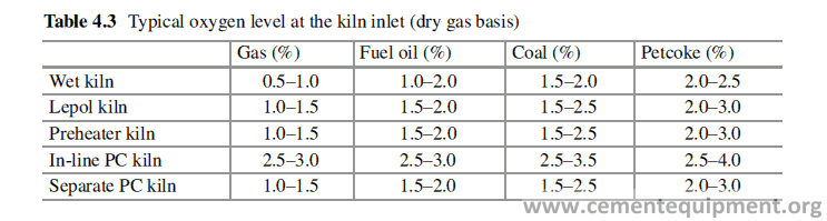
Therefore a slight reduction of the amount of excess air increases the flame tem-perature a little. Extremely low excess air (or oxygen) reduces the flame tempera-ture, which lengthens the flame (post combustion) and lowers the fuel efficiency. Additionally sulfur and alkali volatilization is enhanced, which may lead to buildup and incrustation problems within the kiln system.
Too much excess air (or oxygen) cools the flame too and leads also to a poor thermal and fuel efficiency, due to the deteriorating heat transfer. Since the total gas flow is increased, the kiln internal and external dust cycles also increase.
Hence lower oxygen levels are chosen, if sulfur volatilization is not problematic.
A general rule applies that at the minimum permissible oxygen level, no notable CO is formed (i.e., <0.05% at kiln inlet).
Control Variables
In order to run the kiln in a smooth and efficient manner, the control parameters must be kept in a narrow range close to target. To keep the control parameters close to target, it is generally necessary to make adjustments to the main control variables which are:
- Fuel rate to the kiln
- Material feed rate to the kiln Kiln draft
- Kiln speed
- In case of pre-calciner systems: fuel rate and draft in the pre-calciner
- In case of grate coolers: grate speed
The effect of the control variables, on the operational parameters, mentioned before, is as follows.
Fuel Rate
When the fuel rate into the kiln is increased:
- Burning zone temperature increases
- Back-end temperature increases
- Oxygen concentration decreases
A decrease of the fuel rate has the inverse effect.
If more energy is introduced into the system, the BZT and the BET rise and oxy-gen level drops, since part of the excess air is consumed for the combustion of the extra fuel if the combustion does not take place under reducing conditions.
Feed Rate
When increasing the material feed rate into the kiln:
- BZT decreases
- BET decreases
- Oxygen concentration decreases
A decrease of the feed rate has an inverse effect.
When more feed is introduced into the kiln system, the temperature starts to drop first at the back end. After the higher amount of feed has reached the burning zone, the BZT starts to decrease also.
The extra feed releases additional H2O and CO2. The additional amount of gas from the meal reduces the quantity of combustion air (and thus of excess air), since the amount of exhaust gas remains (almost) constant. This leads to a decrease of oxygen in the exhaust gas.
Kiln Draft
When increasing the draft in the kiln:
- BZT decreases
- BET increases
- Oxygen concentration increases
A slight decrease of the draft has an inverse effect. If combustion takes place under reducing conditions (too little excess air), the BZT drops again and BET rises.
When the kiln draft rises, more (slightly colder) secondary air is pulled into the kiln through the burning zone. This decreases the flame temperature, and as a result the BZT drops. Although the amount of heat supplied to the kiln system is somewhat higher (more secondary air), less heat is released in the burning zone (lower flame tempera- ture results in reduced heat transfer); thus the BET rises. The higher kiln draft increases both the oxygen concentration and the volume of the exhaust gases.
Kiln Speed
When the speed of the kiln increased:
- BZT decreases (temporarily)
- BET decreases (temporarily)
- Oxygen decreases (temporarily)
A decrease of the kiln speed has the inverse effect.
When the kiln speed is increased, the meal advancement is faster. All reaction zones shift temporarily downwards, which cause the BET and the BZT to drop.
Since more meal enters temporarily in the drying and the calcining zone (same effect as an increased feed rate), a higher amount of H2O and CO2 is released, which leads to a drop in the oxygen concentration.
Those effects are only temporary, since a higher kiln speed at a fixed feed rate reduces the filling degree in the kiln. Once the kiln filling degree has been lowered in the entire kiln BZT, BET, and oxygen concentration gets recovered. In almost all kiln operation the kiln speed depends on the kiln feed rate. The objective is to keep the filling degree in the kiln constant. Thus the kiln speed which under normal oper-ation conditions is not an independent variable, is adjusted in tandem with the kiln feed rate.
Chemical Parameters
The quality of cement clinker produced is controlled by many chemical parameters, developed through the long year of experiences of the cement technologists. Some of these factors are discussed here [4, 5]. On raw mix basis
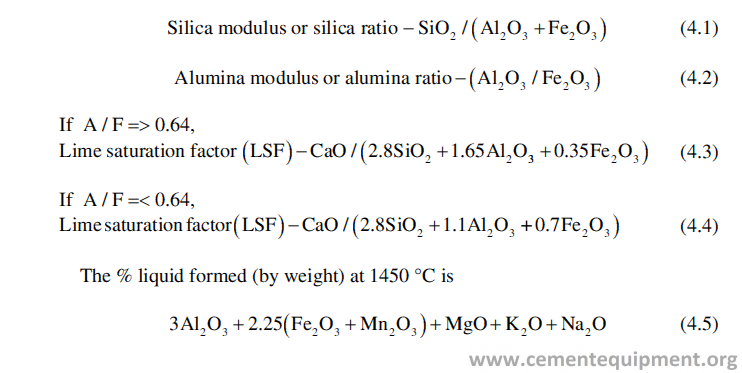
based on the raw meal chemistry. If the value is 30%, the coating will be dense and firm, and if it is 20%, the coating is loose and porous.
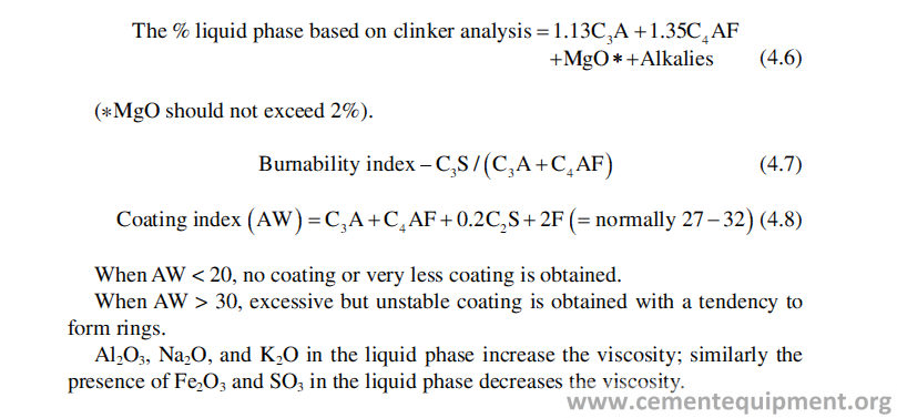
Start-Up and Shutdown
The start-up and the shutdown of a kiln system are the most critical phases during kiln operation. Most serious equipment failures and accidents, which are caused by the operation itself, happen usually during these two periods. Therefore special cau-tion and attention have to be paid to the kiln system before and during start-up and shutdown.
Heat Up
The heat up of the kiln is done following a preset time – temperature schedule, which is determined mainly by the kiln dimension and the type of refractory lining. The other factor to be taken into consideration is how much of the old lining is replaced. Heating rate is slower in case of complete new lining and slower if it is a part lining. The kiln is periodically turned 90 degrees during preheating, in order to avoid unbalanced heating of the kiln shell. The rotation schedule should be aligned with the preheating curve. The kiln should be turned continuously once the BET has reached 750 °C and should be done earlier in case the kiln is exposed during rain. The time-temperature curve for heat up is shown in Fig. 4.6. Occasionally introduc-ing small amounts of kiln feed during preheating will help the bricks to set during heat up (especially, if the bricks are just installed). This will also help to prevent brick migration during periods of continuous kiln rotation.
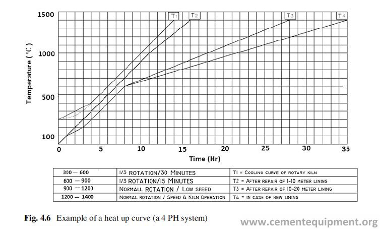
Shutdown
In case of short shutdown, all fuel input to the system is to be shut off and the draft in the kiln to be reduced to a minimum (to avoid overheating of the back and to maintain the burning zone hot). However in some plants, a maintenance flame is re-established in order to help maintain kiln temperature.
In case of a long-term shutdown, a certain draft in the kiln is to be maintained, but overheating of the back (cool the system as fast as possible) is to be avoided. In case of heavy rain, the kiln with the auxiliary drive is to be turned on for minimum 30 min. Later the kiln should be rotated gradually by 90 degrees, in order to avoid unbalanced cooling of the kiln shell. Unless requested for a kiln relining, the kiln should never be run empty.
Unnecessary haste during preheating and shutdown of the kiln may lead to severe refractory problems and may outweigh the time and production saved because of fast preheating and cooling down of the kiln.
Selection of Refractory
Introduction
Refractories should always be designed and installed to provide, wherever possible, a balanced and predictable economic life. There are many reasons for the shutdown of the kiln, but the reparation, if due to Refractory problem, needs the total cool down of the kiln which is very problematic and expensive. It is therefore important to get a Refractory life which coincides with the scheduled maintenance of the plant, and normally it is 12 months or 24 months, rather than 14 months or 26 months [1].
Because of wide variation in the size, capacity, raw materials, fuels used, and the operational practices, it is not possible to provide a standard recommendation for Refractory use, which any plant can adhere to. But it is desirable to follow a general guideline which will improve the Refractory performance in each zone of the kiln and in all other ancillary equipments with minimum cost and minimum failure of Refractory lining [2].
Refractories are mostly tailor-made products. A Refractory, performing well in any particular equipment, in a particular plant, does not always guarantee the simi-lar performance in the same equipment in another plant. Therefore, it demands a careful and thorough study of the conditions prevailed in individual plant before selecting the suitable Refractory lining.
Although qualitative rather than quantitative, a hypothetical relationship can be proposed (Table 5.1), indicating the physical and chemical properties that exert an influence on the rate of wear by common mechanical, thermal, and chemical factors [3]. This table can be utilized to compare the suitability of a refractory compared to others for a certain application where the factors responsible for the damage of the Refractories are identified to a certain extent.
The overall use and consumption pattern of shaped, unshaped, and insulation Refractory in different areas of application in a cement plant is shown in Fig. 5.1.
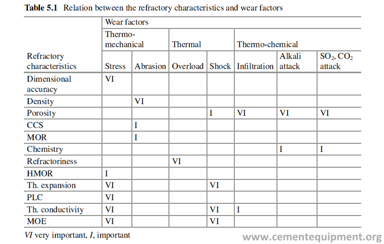
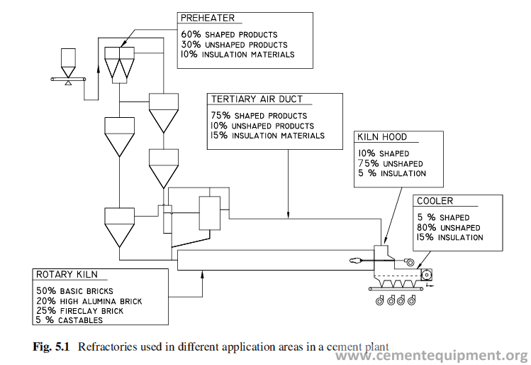
Refractory Selection
Refractory selection in different equipments is done taking into consideration the operational condition prevailing in that equipment and the target campaign life. It is also essential and important to understand the flow of solids and gases through the entire cement kiln system as shown in Fig. 5.2.
Cyclones and Ducts
The cyclone system is a very important element in the cement manufacturing pro-cess. Each cyclone system is unique in its design and operating characteristics and is decided by the factors such as raw meal composition, the nominal and peak throughput, and the type and quality of the fuel burnt in calciner or smoke chamber. The cyclones are designed always to meet the objective to achieve higher thermal efficiency and greater kiln capacity which place high demand on Refractory lining and anchor system.
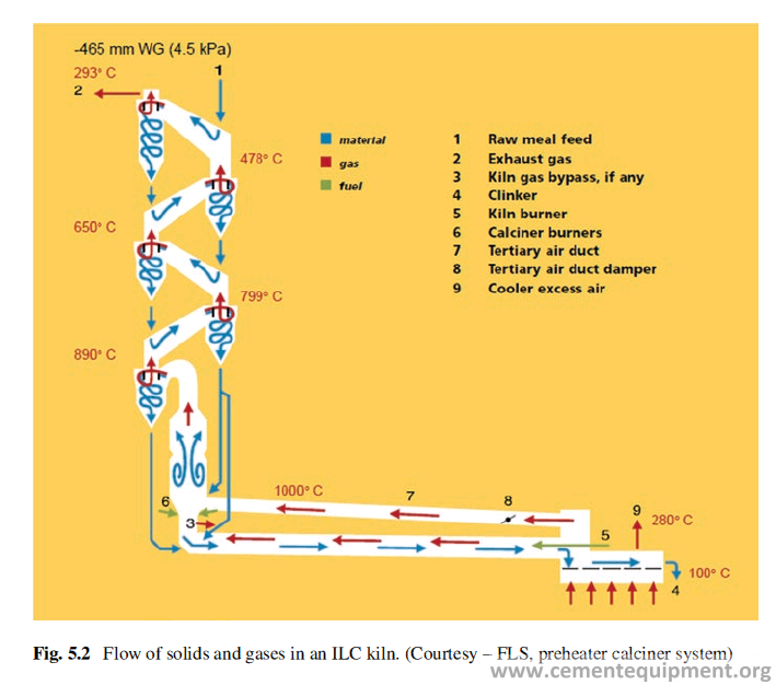
The criteria for a good Refractory for lining in the cyclone and ducts are:
- It must be able to withstand high temperature.
- It must be able to withstand the chemical attack of alkali, chlorides, sulfur oxides, and transition metal oxides at elevated temperature.
- The Refractory must meet the construction requirements of increasing size of cyclones to form a stable lining.
- The Refractory surface must not support the buildups on its surface.
- The Refractory surface must be smooth to reduce the resistance to gas flow inside the cyclone.
Higher operating temperatures, particularly in the lower cyclones, require use of refractories with high refractoriness and high strength. With higher temperature, corrosive vapors can penetrate high into the cyclone Refractory system, so alkali- and chloride-resistant refractories should be used [4].
Buildups are usually caused by chemical attack, in combination with Venturi effect in the cyclone’s complex design, and can also be caused by rapid temperature drops. Buildups reduce cyclone efficiency, and their removal ultimately requires a production stop. Regardless of the method used, removal is a risky job. In the most severe cases, explosives are used. Several mechanical alternatives exist, none of which is particularly satisfactory.
Chemical attack in the form of alkali penetration is unavoidable in cement pro-duction. The worst damage occurs in lower cyclone stages and riser ducts, kiln inlets, and even recliners. Alkali and acid vapors infiltrate the refractory linings and attack the binding phase at temperatures as low as 600–700 °C, thus endangering the lining. When these gases penetrate behind the refractories, the effects are even worse because Cl2 and SO2 combine with condensing steam to form acids that cor-rode anchors and kiln shell. If proper attention is not paid, this can lead to lining collapse. The safest, most cost-effective method to deal with this is to reduce the amount of insulation used, in order to move the vapor’s “dew point” outside the shell of the cyclone. If refractory and cyclone external shell temperatures remain above 100 °C, ambient moisture and chemical vapors will not condense, and acid formation will be prevented.
The temperature varies from 300 °C to 900 °C from cyclone 1 to cyclone 5. The same quality of refractory can be used in all the cyclones with different thickness of working lining and insulation lining to achieve the skin temperature as per the design.
Some properties of the bricks and castable suitable for the lining of the cyclones are given in Table 5.2.
The prevailing operating temperature and atmosphere inside the cyclones sug-gest the suitability of dense aluminosilicate Refractories with 40–50% alumina, low porosity, and high alkali resistance and do not allow high buildup. As an insulation material, calcium silicate board will be most ideal. Where buildup and alkali attack are the major problem, aluminosilicate refractories containing SiC (silicon carbide) or zircon help to reduce the buildup and alkali attack. SiC reacts at high temperature with atmospheric oxygen to form a glassy layer of SiO2 on the refractory surface which prevents buildup; similarly the zircon at high temperature decomposes to form SiO2, which forms a glassy coating over Refractory surface. Zircon is better,
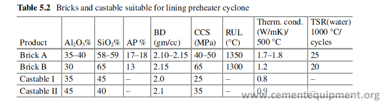
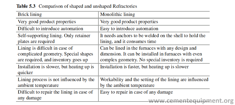
because it has lower thermal conductivity than SiC which helps to save anchors from overheating [5].
The ideal lining thickness for any area of the preheater is the minimum thickness required to attain the specified shell temperature. In the case of monolithic lining, if it is too thin, the anchor may get overheated which can accelerate corrosion, scale formation, fatigue, etc. and may lead to collapse of the lining. If the lining is too thick, then sharp temperature gradient inside the lining may cause crack and spall-ing of the lining.
In the preheater the fine dust behaves like fluid, and very often the red-hot dust infiltration behind the refractory lining causes failure to the lining. The failures are caused by, sometimes, shearing of anchors or the shrinkage of insulation due to sintering in contact with red-hot dusts or by bulging of the brick lining due to push-ing of the lining from behind.
The Refractory used can be both in shaped or unshaped form, but which one is more preferable is a controversial matter. Performance wise both are good and both have some merits and demerits. The advantages and disadvantages of brick and monolithic lining are shown in Table 5.3.
The installation of monolithic lining is faster and easier than brick lining. But the installation of monolithic Refractory is more critical than brick lining. Brick is a finished product, but castable is a semifinished product and needs much attention and care during installation.
In the brick lining, the shape of the brick is important, especially when the diam-eter of the cyclone is more. The brick shape and size must be designed to have an interlocking arrangement to avoid bulging out of the lining. In the case of mono-lithic lining, the anchor design is very important to attain the stability of the lining.
The common mistake made during selection of Refractory is to put the speed of installation ahead of the lining stability. If the preheater lining life is 2–5 years with-out repair, then installation time should never get the priority.
Calciner
The thermal efficiency of the cyclone system improves a lot when the recycled hot air from the cooler is delivered to the calciner through the tertiary air duct. Fuel cost is also reduced by using the cheaper alternate fuel in the calciner. At higher operat-ing temperature, chemical attacks are more severe in calciner compared to cyclone. The suitable refractory for the calciner must have high refractoriness, high thermal shock resistance, and high resistance to chemical attack by alkali, chlorides, and sulfur oxides. The refractory in calciner also should have high abrasion resistance because large volume of dust-laden gas is delivered in calciner at high velocity through the TAD. The selection of right kind of insulation is also very important to prevent energy loss. The use of alternate fuel like plastics, municipal wastes, etc. may pose serious problem like early wear in central pipe.
Besides reacting with the refractory material itself, alkali vapor penetrates inside Refractory lining and attacks the metallic parts like anchors, and the stability of the lining may be greatly reduced.
Three main areas of the calciner are cone, wall, and roof. Both the shaped and unshaped refractories can be used to line all these areas of the calciner, but the Refractories must have the desired properties as mentioned before to ensure satis-factory performance. It is better to line the roof with castable which has lower per-meability compared to brick lining.
The typical properties of the Refractories, suitable for calciner, are shown in Table 5.4.
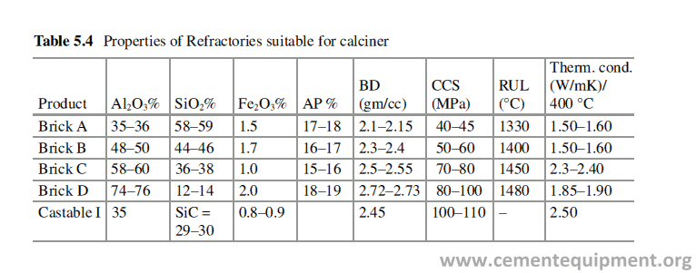
Riser Duct
It recycles hot air from the lower stage cyclones to kiln improving the thermal effi-ciency of the process and reduces the fuel cost. Riser duct lining often faces the problem of buildup especially in the curved sections.
The closer the duct is to the hot end of the cyclone system, the greater is the alkali penetration and spalling of the Refractory. The alkali vapor penetration can cause severe alkali bursting, where the Refractory volume can increase by ten times from normal volume [6]. The typical properties of the Refractories, suitable for riser duct lining, are shown in Table 5.5.
Smoke Chamber
It experiences the worst possible exposure to high temperature (1300 °C), alkali attack, buildup, anchor corrosion, etc. The Refractory selected for lining inside this equipment must have low porosity and low permeability, and the best choices are dense bricks or low cement castables. The typical properties of the Refractories, suitable for smoke chamber lining, are shown in Table 5.6.
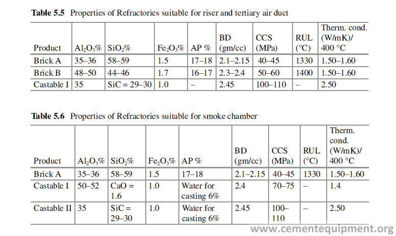
Meal Pipes
It connects the cyclones and has smaller diameters. The meal pipes are made in small sections. They are lined in ground level and then are transported to the area of installation. The main property required here is to withstand the continuous abra-sion of the meal material. It can be lined with both bricks and castables. The typical properties of the Refractories, suitable for meal pipe lining, are shown in Table 5.7.
Insulation
The total heat loss by radiation in the preheater is less than 2% of the total heat input. Most preheater vessels and ducts are insulated to protect the steel shell. The use of refractory fiberboard as insulation, in the hotter sections of the preheater, may induce premature lining failure, if the fiberboards fail behind the dense lining. Fiberboard contains a certain amount of organic matter that, when exposed to mod-erately high temperatures, burns out with emission of fumes and loses both its mechanical strength and insulating property. The loss of insulating property exposes both the steel shell and the anchor stem to higher temperatures resulting in relative movement and damage of the anchoring system and inducing cracks on the dense lining.
To avoid such problems, an insulating material with the minimum amount of loss on ignition, e.g., calcium silicate, diatomaceous earth, or vermiculite boards, or insulating castables that can be cast, gunned, sprayed, or pumped in place should be selected.
Kiln Hood
The kiln hood for lining purpose can be divided into two halves. The upper half, consisting of the ceiling and sidewall, experiences high-temperature radiation, abra-sion, exposure to alkali vapors and sulfur oxides from secondary air, and thermal shock, when there is kiln shutdown. It is best to line the area by 50–75% alumina bricks or dense low cement castables. There is report of good result of silicasol-bonded castable in this area [7–9]. If the temperature of the secondary air is above 900 °C, then magnesia-spinel refractory can be a good choice also.
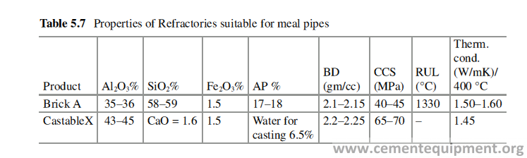
Another interesting alternative, finding more and more acceptance in cement plants, is the modular lining which offers the advantages of both bricks and casta-bles. In this alternative the castable is precast and pre-fired into blocks that have the insulation and the anchoring system pre-attached.
The lower half of the hood towards the cooler side can be lined with silicon car-bide or zircon-containing high alumina Refractories. The buildup of coating occurs in this area, and the said Refractories will repel the coating. The typical properties of the Refractories, suitable for kiln hood lining, are shown in Tables 5.8 and 5.9.
Insulation
The kiln hood lining must use the insulation at the back with the steel shell. When the working lining thins down by wear, the insulation will save the steel shell from overheating and warping. The integrity of the insulation is critical to the working lining integrity. If hot clinker dust penetrates the insulating layer behind the dense castable or brick, it quickly damages the anchoring system and pushes the lining away from the shell until it collapses.
Most insulating materials shrink at hood temperatures and make the situation even worse. The insulating material for application in hood is chosen such that it contains no organic binders and its limit of service temperature is above 1000 °C to retain its full integrity at that temperature. Either calcium silicate of 1100 °C grade or insulating castable is the best choice for that area of application.
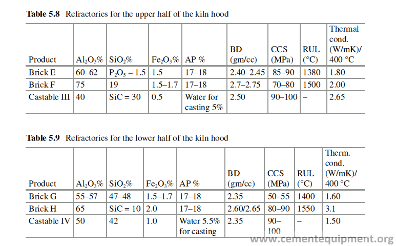
Tertiary Air Duct and Cooler
TAD recycles the heat from the hot clinker to the kiln. Air from the grate cooler, laden with highly abrasive clinker dust, travels through the TAD at a very high velocity (25–30 m/sec) at high temperature (about 1000 °C) and poses a very high abrasion on the refractory lining especially at bends and dampers. Therefore the selected refractory to line the TAD must have very high abrasion resistance and alkali resistance.
Grate Cooler
Clinker enters the cooler at a temperature of around 1200 °C and heats up the grate and surrounding refractories rapidly. High refractoriness, high abrasion resistance, and resistance to thermal shock are necessary, especially at the clinker downfall area and bullnose. The cooler walls directly above the grate are also subjected to extreme wear. The partition wall, designed to limit the inflow of cold air to the kiln system, must withstand the abrasive effect of clinker dust entering the tertiary air duct as well as the temperature fluctuations, resulting from its exposed position.
The cooler is effectively divided into two zones – the “hot” zone and the “cold” zone. The first zone is from the clinker downfall to the bypass duct and partition wall. The purpose is to exchange the heat from the hot clinker and route it back to preheater via the tertiary air duct. The function of the second zone is to ensure a uniform reduction of temperature of the clinker body from 800 °C down to ambient. The Refractories to be used here must have high abrasion resistance and high ther-mal shock resistance.
Both bricks and monolithic can be used to line the kiln hood. To get good refrac-tory life and the fastest possible installation at the clinker downfall, bullnose, front sidewalls, and roof, precast refractory blocks, which can be quickly bolted into place and just as quickly removed, can be used.
Kiln
Kiln is the heart of the cement plant where the clinkerization takes place at high temperature. The kiln is a cylindrical horizontal tube with a very little inclination of 1–2 degree. The kilns have diameter 3–7 m and length 50–100 m. The kiln rotates on its horizontal axis at a speed of 1.5–4 RPM.
The Refractory lining of a modern cement rotary kiln is performing different specific functions at different zones of the kiln, which include:
- Protection of the kiln shell and tires from attaining an excessive temperature which can deform the shell
- Protection of the kiln shell from the corrosive gases and liquids
- Protection of the kiln shell from mechanical abrasion by the feed material and
the clinker
- Reduction of the thermal energy loss to keep it within tolerable limit
- Increase of heat exchange between the hot gases and the feed material
The kiln can be divided into several zones depending on its temperature at different zones and also function being performed. Table 5.10 shows the length norms of different zones in different types of kilns.
Refractory selection for different zones is done based on the operational environ-ment. The temperature profile and the refractory practices followed for different zones in the kiln are shown in Fig. 5.3 [10, 11].
Inlet Cone
The most important considerations for the bricks here are that those must be able to withstand high abrasion, thermal shock, and alkali attack. Therefore 40–50% alu-mina fireclay refractories are found to work best in this area. Both shaped and unshaped refractories can be used in this area. The typical properties of the refrac-tories suitable for lining are given in Table 5.11.
Preheating Zone
The Refractories in this zone must be able to withstand high mechanical abrasion by the moving calcined feed material and alkali attack. Fifty to sixty percent alumina refractory bricks are the best lining material for this area. The typical properties of the aluminosilicate refractories suitable for lining different zones of the Kiln are given in Table 5.9.
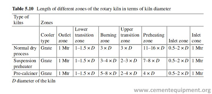
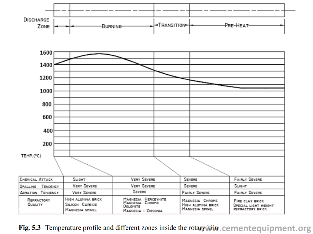
Transition Zone
Here the Refractory lining is exposed to:
- High temperature and also cyclic temperature fluctuations, because there will be no coating or unstable coating
- Radiant heat of the flame
- Attack by alkali salts and alkali vapor
- Attack by the liquid phase in the cement which will start and attack by other cor- rosive gases if alternate fuels are used
- Redox reaction cycles when there is variation in oxygen potential due to change in fuel
Magnesia alumina-spinel refractories are the best material to line this area, espe- cially when the furnace is with large diameter. The magnesia-alumina refractories have the property to withstand high thermal shock. It has low MOE to withstand high thermo-mechanical stresses, and it can withstand the chemical attack of alkali salts, corrosive gases at high temperature, and cyclic oxidizing and reducing conditions.
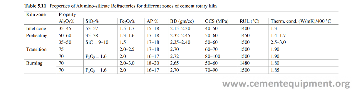
With smaller diameter kiln, normal high alumina refractories and phosphate- bonded high alumina refractories with 70% alumina also work well. High alumina refractories because of their pyroplastic property can withstand the high deforma-tion without getting crack. It has also a good thermal shock resistance. High alu-mina Refractories also take up good coating which protects it from all abuse.
Burning Zone
It is the most important area in a cement plant where the clinkerization takes place.This zone experiences:
1-Highest temperature.
2-Reaction with the liquid phase formed in cement.
3-Continuous temperature fluctuation between when the lining is in contact withthe clinkers at the bottom and when it is at the top farthest away from the clin-kers. The temperature fluctuation gets further aggravated, if the coating becomes unstable.
4-Reaction with the sulfur oxides and other gases, e.g., chlorine, generated from alternate fuels.
5-High abrasion from the clinkers.
6-Different kinds of thermo-mechanical stresses.
Fortunately a thick coating of the cement clinker is formed on the refractory lining in the burning zone, which minimizes the damaging effects of the said factors on the lining and enhances its campaign life. The process people in the cement plant always pay attention to maintain a stable and thick coating on the burning zone refractory lining. The stability of the coating depends on many factors which will be discussed later.
Thermal load is one of the most crucial parameters to decide the lining quality. The thermal load (TL) is defined as the heat consumption per hour per unit cross section of the kiln, and usually it is expressed in terms of GJ/m2h:
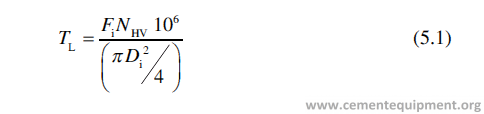
where Fi = fuel burning rate per hour (kg/hr), NHV = net calorific value of the fuel (KJ/kg), and Di = effective internal diameter of the kiln after Refractory lining.
With increasing production per net kiln volume (ton/dm2), the thermal load increases, and lining material must be designed accordingly to be able to take up that thermal load.
It is found through experience that the normal thermal load of cement kiln remains in the range 14–22 GJ/m2h, whereas the recommended maximum thermal load in the burning zone is 24.3 GJ/m2h. It is found by experience that up to a ther-mal load of 13 GJ/m2h, high alumina bricks are working satisfactorily, when other operational parameters are within tolerable limit. Beyond this value of thermal load-ing, basic refractories, e.g., magnesia spinel, work much better, and if the thermal loading exceeds 21 GJ/m2h, special care must be taken in selecting the refractory. In such case very pure grade of magnesia alumina or magnesia-zirconia lining should be used.
For large diameter kilns where the thermal loading is high and alternate fuels are used, the basic refractories are preferred over high alumina products, but the Bauxite based high alumina Refractories are also used very successfully in smaller diameter kilns. The raw material chemistry, fuel used, and operational discipline play a major role in deciding the refractory lining life in burning zone. The selection of the refractory for the burning zone depends upon the kind of stresses the refractory lining is exposed to. The operating conditions that prevail in different cement plants are not same.
The typical properties of some basic Refractories for the transition and the burn-ing zone are shown in Table 5.12.
Before selection of the Refractory, one should know the actual operating condi-tions in the cement plant, under consideration. Table 5.13 shows the suitable quality of basic bricks under different kinds of stresses. To enhance the life of the basic lining in the burning zone Magnesia-Spinel castable has been developed which has shown very promising result in actual field trial where the material was applied by gunning on the worn out lining in the burning zone to build a thickness of 60 mm [12].
Outlet Area (Retainer Ring and Nose Ring)
This is a very critical area in the kiln and highly stressed. The thrust of the whole kiln lining is borne by the retainer ring, and the refractory in contact with the retainer ring is to withstand it. Besides the thrust in this area, the bricks are to withstand high abrasion of the clinkers, and the bricks also experience high thermal shock due to temperature fluctuation. Various designs are tried to minimize the thrust, e.g., to put two retainer rings or to make a conical design to transfer part of the axial thrust in radial direction, but none is found to be a foolproof solution.
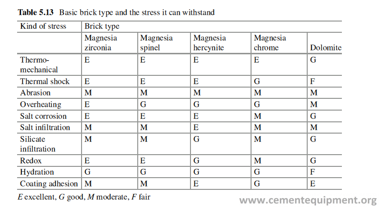
The stress generated on the lining in this zone, because of thermal expansion, was computer simulated and modeled. It shows that the deformation of the lining caused by thermal expansion depends upon the temperature profile across the brick height and the brick quality [13]. During initial lining the cardboards are used as expansion joints. It was found that in the initial heat up, the highest stress produced was confined to one third of the brick height from hot face [13] and the stress pro-duced was lower than the crushing strength of the bricks. But a completely different situation was encountered after kiln shutdown and reheating. The expansion joint provided during initial lining is lost due to downhill movement of the lining. Moreover all the open joints are filled up with clinker dust and the residual expan-sion of the lining made it further worse. The brick next to the retainer ring is sup-ported. Only 70 mm of the brick height, next to the retainer ring, is supported by the retainer ring, and a high shear force is generated which is much higher than the brick strength resulting in crushing of the brick (Fig. 5.4).
To combat this problem, RHI has developed a design to increase the contact sur-face area by providing slanting surface as shown in Fig. 5.5. Because of higher surface area, the force per unit will be lower to save the bricks from getting crushed [14].
In the nose ring area, the main factors, which make this area critical, are high abra-sion of the falling clinkers and high thermal shock as it is exposed to atmosphere.
The material to be used in the nose ring must have high volume stability, abra-sion resistance, and thermal shock resistance. The properties of some ideal material used for lining this area are shown in Table 5.14. Silica sol-bonded or no cement castable is also tried in this area with great success [7].
Along with the castable quality, the design of anchors is also very important for the successful performance. It has been found that specially designed precast refractory blocks with very high content of stainless steel fiber work very well in this area [15].
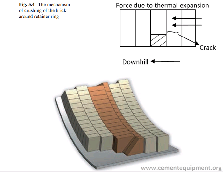
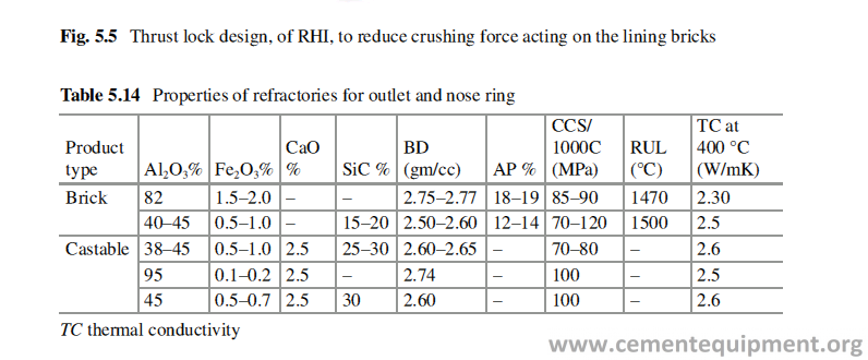
Brick Shapes for the Kiln Lining
The brick shape used for lining of the rotary kiln is side arch bricks. Normally the kilns are lined with brick shapes with two different tapers. Two different systems of refractory sizes are very popular, one is VDZ and the other is ISO, shown in Fig. 5.6. Two shape bricks system fit better in the rotary kiln lining because often the kiln shells are not perfectly circular. By changing the ratio of two different bricks, the distorted area in the kiln can be lined better. Some practical thumb rules used for the lining are:
- Basic bricks should be lined in the VDZ shapes because VDZ bricks are thinner compared to ISO sizes and the lining with VDZ shapes has more joints which can accommodate the higher thermal expansion of the basic refractory.
- Kiln lining with larger diameter needs bricks with more taper, and preferably ISO shapes should be used.
- At the kiln tires because of the higher shell ovality, VDZ brick shapes should be used because of their flexibility with more number of radial
- Handling of ISO bricks is more stressful for lining crews because of their greater weight compared to VDZ shapes.
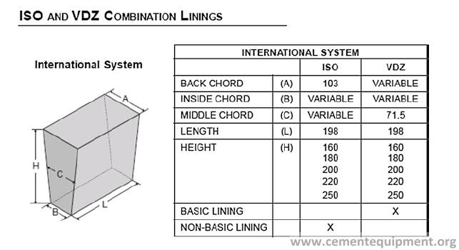
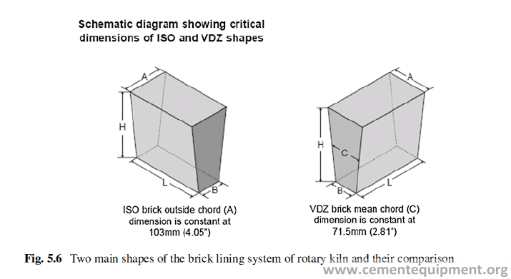
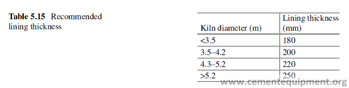
There is no proven corelation between the brick lining thickness and its cam-paign life. Sometimes lining with 160 mm brick thickness gives better refractory life than 220 mm thick lining. Actually the radial stress, which crushes the brick, increases with lining thickness. The ideal thickness of the lining should be the mini-mum thickness of the lining which will not allow the shell temperature to exceed the acceptable limit. The normal recommended lining thickness is given in Table 5.15.
It is to be borne in mind also that the key effect of the bricks in the lining becomes more prominent with higher length of the bricks and in bigger diameter kiln the brick lining with longer bricks is more stable.
Calculation of Combination of Two Different Brick Sizes
The number of bricks of each size used in the lining can be calculated by using the mathematical formula given below.
If Na and Nb are the number of pieces required of shapes A and B to form a ring in a kiln with inside diameter D, Xa and Xb are the a and b sides of shape A, and Ya and Yb are the a and b sides of brick B, then
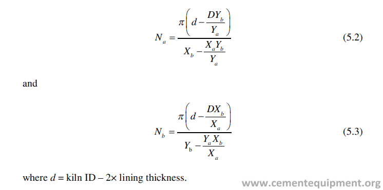
Refractory selection in burner pipe must take into consideration the following
factors:
- High temperature
- Thermal cycling
- Alkali attack
- Sulfur attack
- High abrasion of clinker
- Low thermal conductivity to protect the steel pipe inside
It is not possible to get the best of all these properties in one material, and there- fore a balance is struck to optimize the different properties to get a best suitable material. Castable is the type of Refractory used to line the burner pipe.
Since the main requirement of a burner pipe lining is to protect the metal pipe inside, so an insulation cloth or paper must be wrapped on the pipe and then casting is done. The lining thickness is normally 100 mm. The front 1.5–2 m of the burner pipe is the most vulnerable area where damage takes place in service. In order to reduce the cost, the zone lining can be done in the pipe. In zone lining 2 m from the tip is cast with the best castable, and beyond that lining can be made with normal castable with lower price.
The main reason for damage of the castable lining of the burner pipe is the dif- ferential expansion and contraction of the castable and the anchors [16]. To mini- mize this effect, the anchor design is very important. The anchor must be designed in such a way that it can accommodate the expansion of the castable lining material [17]. The anchors are to be covered with bitumen paint or wax, which when burns off, creates a gap for the play of the castable. Instead of rigid anchors, the floating anchors, which can accommodate the movement of castable, enhance the perfor- mance. The stainless steel fiber reinforcement in the castable resists the abrasion and thermal shock better and improves the performance. Properties of some cast- able suitable for lining the burner pipe are given in Table 5.16.
Silica sol-based castable has been tried successfully in the burner pipe lining [9, 18].
The report is also there that specially developed magnesia-spinel castable shows very promising result in the lining of the burner pipe [19].
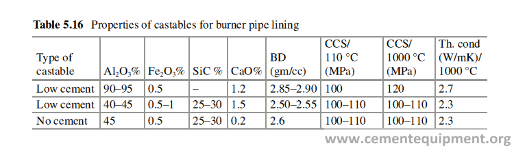
Refractory Design, Installation, and Maintenance
Introduction
Refractories can be a substantial investment for a cement industry, either in new construction or in repair work. Installation of refractories may comprise a small part of the entire budget, but it protects the equipment, protects the people, and protects the production, and their value is greater than its cost. Refractory performance depends on the quality of installation to a great extent. The best quality of Refractories does not ensure the best performance, unless the Installation quality is sound. Installation techniques are different for different types of Refractories. Installation methods of shaped and unshaped products are quite different. Complete knowledge on the character and properties of the refractory products under installa-tion is required for good installation. Refractory lining inside each equipment in a cement plant like calciner, cyclone, TAD, cooler, Kiln, etc. needs proper planning and utmost care and precaution. Any premature Refractory failure needs a shutdown to set it right and causes huge loss in profit because of production loss.
General methods and principles followed in Refractory installation are the same as followed in civil engineering construction, and it is the same irrespective of the equipment. But the major difference is that the whole refractory lined structure will remain at an elevated temperature during operation. Therefore some special tech-niques are followed to take care of stresses generated because of higher operational temperature. Installation of Refractories in some of the equipments, for example, Rotary kiln, because of its geometry and of its dynamicity, needs special care.
Refractory Lining in Rotary Kiln
Rotary kiln is the heart of a cement plant and single most important equipment in a cement industry. Most of the unplanned shutdowns for refractory maintenance, in cement plants, are due to the refractory problem in rotary kiln. It is to be borne in mind that Rotary kiln is huge in size and mass and is not stationary but dynamic in nature, which has made it very special from other static furnaces. A kiln of 6 m diameter and 60 m length, for example, including Refractory lining and feed weigh about 1100 MT [1]. When such a huge structure, with huge mass, rotates on two or three supports, different types of thermo-mechanical stresses are generated in the Refractory lining, and therefore lining perfection is very much needed to reduce the effect of those stresses. The following points must be taken into consideration before starting refractory installation, in any rotary kiln or in any other equipment as well.
Storage
The refractories for lining must be kept under covered space so that the bricks do not get wet, especially in case of basic bricks and monolithics. In case of lining basic brick along with other nonbasic refractories, all the products must be used in dry condition to avoid any kind of hydration of the basic bricks. Wet basic bricks should not be exposed to a temperature above 50 °C.
Tools and Tackles
All tools must be inspected before starting the lining job. The common tools used for installation are:
(a) Rubber or plastic hammers of different sizes to align the laid bricks and to close the joints
b) Brick cutting machine to cut the bricks as per requirement, specially to close a ring or a lining wall
(c) Trowels to apply and spread the mortars on brick surface
(d) Measuring tapes
(e) Spirit level
(f) Plumb
(g) Chisels, etc.
A pneumatic or hydraulic jack is preferred to assist in the jacking and closing out of each brick ring. The jack should have a pressure dial capable of reading up to 4000 psi. Automatic lining machine (Fig. 6.1) is also used largely for lining which makes it faster because the kiln need not to be turned after lining the lower 180 degree [2].
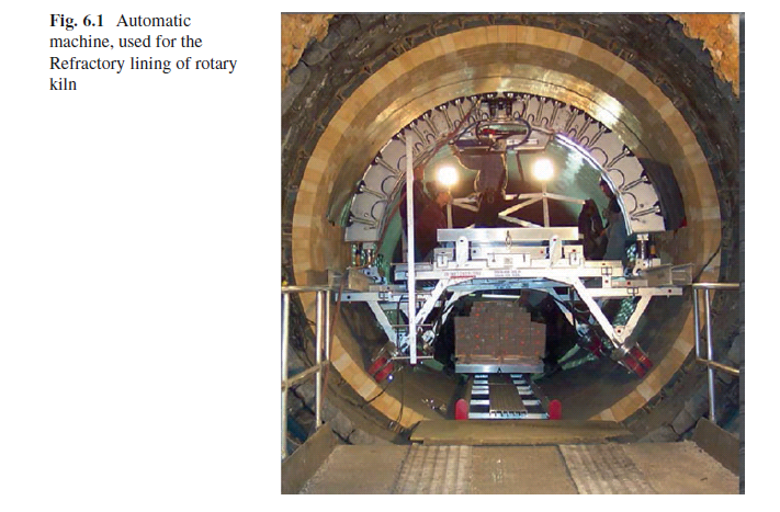
Preview of Drawings
A thorough review of the installation drawings, with the customer, installer, and refractory supplier, should be made, before installation begins.
Kiln Shell Inspection
Both internal and external appearance of the kiln shell must be inspected thoroughly before the lining starts. For any abnormalities in kiln shell, special care must be taken. The kiln shell inside must be clean and free of any debris. The brick must be seated firmly on the shell with tight brick-to-brick contact.
Reference Line: Longitudinal
As a first step to start the kiln lining, longitudinal reference line should be estab-lished on the lowest part of the shell (6 o’clock position) along the length of the kiln, to be brick lined. A bar is kept horizontal inside the kiln with the help of a spirit level (Fig. 6.2) [3]. A string, with a weight at one of its end, is hung from the center of the bar. The point, where it touches the shell, is noted. The similar readings are taken at several points along the length of the kiln. The points obtained are joined to get accurately the longitudinal line. This longitudinal reference line must be parallel to the axis of the kiln shell and will be used to start laying brick for each ring. Construction of these lines can also be done with the help of a long spirit level kept in a similar way as the wooden bar is kept. The level is adjusted and the center is marked on the kiln shell. Longer is the spirit level better is the accuracy.
Additional parallel lines at 1.5 m intervals should also be drawn on the shell (Fig. 6.3). Nowadays, more sophisticated method is available using laser to con-struct the longitudinal reference line (Fig. 6.4).
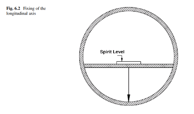
Reference Line: Circumferential
In the next step of the construction, circumferential reference lines are drawn. These lines are constructed perpendicular to the longitudinal reference lines made earlier. Obviously the circumferential reference lines are perpendicular to kiln axis also. The reference lines (Fig. 6.3) are essential to ensure the accuracy of the installation and to help keep the rings straight and to maintain the joint tight [3]. The bricks are laid on this mark, and the bricks are now put on both the sides of this line one by one to form the ring which will be perpendicular to the axis of the kiln. Nowadays more advanced method has been developed to fix the axial line by laser beam, shown in Fig. 6.4. Existing weld joints may be used as circumferential reference line. If the rings are not laid perpendicular to the axis of the kiln, there will always be a chance that lining gets spiraled or skewed during running of the kiln. This causes the loos-ening of the ring and falling down of the bricks from the ring and finally lead to the shutdown of the kiln.
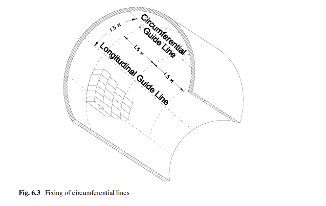
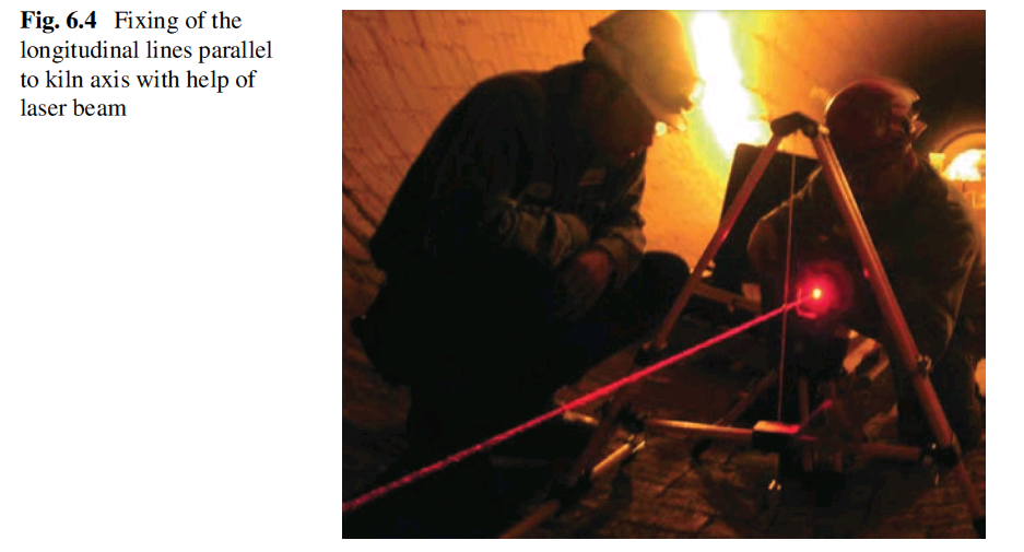
Brick Shapes and Size
Side arch bricks of two different shapes following ISO or VDZ standard (Fig. 5.3) are used for lining rotary kilns. If the kiln diameter is known, then the ratio of two different shapes, to form a ring, can be determined from the available table (Appendix).
Some kilns still use refractory blocks (cupola shapes) having a curved surface to match the contour of kiln shell. Bricks are always installed starting at the downhill end of the section to be lined. During lining the bricks must be tapped with a leather hammer to ensure the proper contact with the shell.
Lining Thickness
The thickness of the refractory lining depends upon the kiln diameter. The standard norm is to use 200 mm thickness for up to diameter 4.2 m, 220 mm thickness for 4.2–5.2 m diameter, and 250 mm thickness for diameter above 5.2 m. The purpose of increasing lining thickness is to insulate the kiln shell from overheating. But it has been found, in actual practice, that with good and stable coating on the brick lining, lower refractory thickness also can be used without any problem.
Many other factors, besides the kiln diameter, should be taken into consideration while deciding a lining thickness. The rigidity of the kiln shell is very important factor. It is defined by its thickness. The thicker shell flexes less with the same grade of steel and same operating temperature. The rigidity of the kiln shell becomes very low above 350 °C because of the decrease of metal strength with increasing tem-perature. A flexible shell with high ovality poses compressive stresses on thick lin-ing and higher risk of brick detachment when the lining gets thinner (Sect. 7.5.1).
The relationship between lining thickness and radial stress on the brick [4] can be expressed as
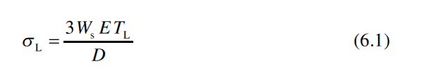
where σL = radial stress, E = modulus of elasticity of the brick, Ws = shell ovality, TL = lining thickness, and D = kiln diameter.
Equation 6.1 shows that other factors remaining constant, increasing the lining thickness, will increase the radial stress on the lining and the radial stress is higher for small diameter kilns than for large diameter kilns. Therefore, larger kilns should have fewer problems with thick linings than smaller kilns.
Laying of Bricks
How the bricks are positioned, in two adjacent rings, is important. The joints of bricks in two adjacent rings should never come in a line because it makes the lining weak. The bricks in two adjacent rings are therefore lined in such a way that the joints get staggered. From the reference line at the bottom of the kiln, bricks are laid up, with bonded joints, both the sides. Depending on the diameter of the kiln and the condition of the shell, the general guidelines are a 1:1 ratio for ISO brick and a 2:1
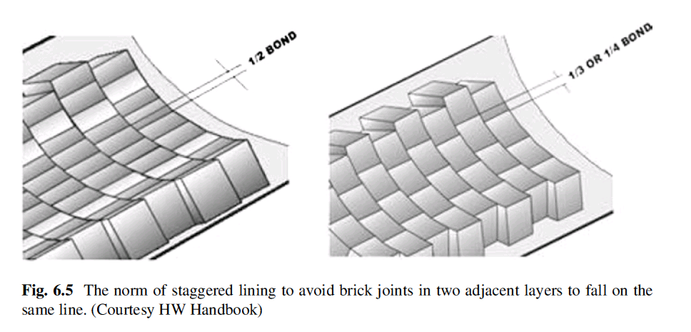
or 3:1 ratio for VDZ brick as shown in Fig. 6.5. Dramatic deviations from these ratios may happen, because of the following reasons:
(a) The shell is not perfectly circular.
(b) The brick’s dimensions are not as per the specification.
(c) The wrong combination of bricks is used.
Each brick used for the lining has two different thicknesses. The side with higher thickness rests on the shell. For easy understanding, a notch is provided on one end of the brick to indicate the hot face. All bricks are to be installed with the notch fac-ing towards the center of the kiln. Any brick installed upside down needs to be removed and replaced in the correct orientation.
Brick rings should be measured to the nearest circumferential reference line at least every 1.5 m of kiln length. Minor corrections should be made with mortar in subsequent rings to compensate for deviations greater than 12 mm [3, 5].
If step forms, during the lining, then correction is needed in the ratio of the two different shapes. The lining must fit very tightly on the kiln shell, and the refractory lining must rotate at the same speed along with the kiln shell. If the brick ring remains loose, there may be a relative movement between the kiln shell and the brick ring of the lining. In that case, the lining gets worn out on the cold face, adja-cent to the shell, because of friction between kiln shell and the brick (Fig. 6.6).
Mortar Joints
The bricks in a ring of the kiln remain tight because of the key effect of the brick as is found in arch construction. Mortars are normally not required to join the bricks in the lining of rotary kiln. But mortar joints are very useful to take care of the kiln shell defect [3, 5] and dimensional inconsistency of the refractory bricks (Fig. 6.7). Mortar lining is more appropriate in the case of basic lining because high thermal
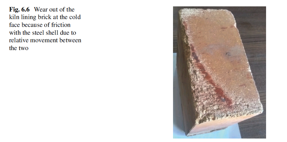
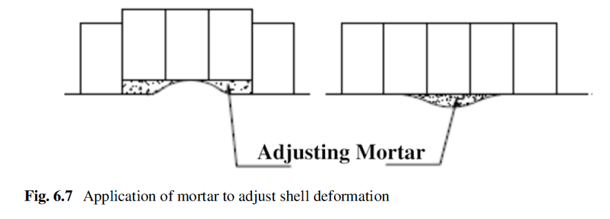
expansion of the basic refractories keeps the lining tight. The mortar joints may shrink at high temperature and may loosen the lining if the thermal expansion coef-ficient of refractory is not high and is never recommended in case of lining with fireclay or high alumina refractories. Mortar’s specification is decided looking into the quality of bricks to be joined. The mortar composition should be close to the brick composition. The mortar is to be mixed with water to get the trowelable con-sistency and should have sufficient workability when applied on the brick surface.
Expansion Joints
This is a very important aspect of all refractory installations. The refractory expands when gets heated up in service. A provision is to be kept to accommodate the ther-mal expansion and to relieve the stress, without which the lining may collapse. It is to be borne in mind that during the operation of a kiln or furnace, the whole refrac-tory lining maintains a temperature profile across its thickness. Therefore the expan-sion will be more at working face and minimum at the cold face. Moreover, the refractories attain plasticity at high temperature and mitigate the compressive stress generated due to restricted thermal expansion. The provision for expansion can be kept in different ways. For example, in case of constructing a ring with refractory bricks in a cylindrical vessel, the total expansion of hot face is calculated consider-ing the circumference of the vessel and operating temperature. Then the expansion per brick is calculated, and the cardboard of required thickness is put after every 5 or 10 bricks.
Calculation of expansion joint – if the diameter is D, the thermal expansion coef-ficient is α, the operating temperature is T, and the number of bricks per ring is N. Then the expansion per brick,
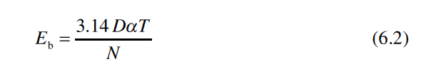
If the brick interval, for providing expansion joint, considered is 5, then the thickness of cardboard to be used to provide expansion joint should have a thickness of 5 × 3.14 DαT/N = 15.7 DαT/N.
In cement rotary kiln, no expansion joint is provided in the rings to keep them tight during operation. During the closure of a ring in the lining, 1–2 steel shims are struck in the joints, and those during high temperature operation of the kiln soften or melt taking care of the thermo-mechanical stress due to expansion. The expan-sion joints are more important in axial direction because of larger length provided in the axial direction of the lining after every 1–2 m length. The thermal expansion joint is, especially, very important for the lining of basic refractories, which have high thermal expansion.
Let us consider the lining of basic refractory over a length of 15 m. Basic bricks have thermal expansion of about 1.2% at 1000 °C. Steel has the thermal expansion coefficient of 12 × 10−6/ °C. If we consider the lining working face temperature is 1000 °C and the steel shell temperature as 350 °C, then the relative expansion of the lining hot face compared to steel shell will be 15000 × [0.012 – (350 − 30) × 0.000 012] = 122.4 mm. The ambient temperature is considered 30 °C. That means the lining hot face will expand 122.4 mm on a length of 15 m of the lining compared to the steel shell. If the required space is not allowed to expand, the tremendous com-pressive stress generated can be calculated easily (Eq. 6.11) which can crush the top portion of the bricks at the plane, parallel to kiln axis. Figure 6.8 shows the damage of 70% Al2O3 refractory bricks in a kiln due to insufficient expansion joints given in the lining in the axial direction. The phenomenon becomes more prominent if the preheating is made faster, when the stress does not find time for relaxation (Eq. 6.12).
But fortunately, in actual practice, a temperature profile exists across the lining thickness, and the temperature of the cold face of the brick remains at a much lower temperature compared to working face, and the effect of thermal expansion is minimized.
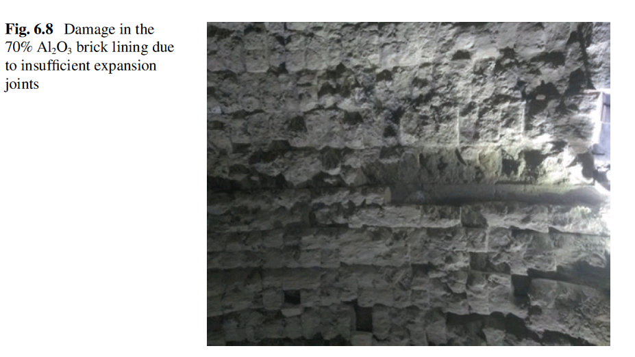
Vertical Wall Lining
In case of vertical lining in a straight or circular wall, steel retainer plate is put after every 15–20 layers, so that the load is distributed on the retainer plates. In that case, ceramic blanket is used to fill up the gap between the topmost brick layer and the retainer ring above to accommodate the expansion (Fig. 6.9).
In any Refractory lining, a temperature profile exists across the Refractory lining between hot face and cold face. In case of cylindrical lining, when the refractory lining is heated up, it starts expanding, and initial stresses are nullified by the read-justment of lining material and compression of mortars, in case of mortar joints in the brick lining. At still higher temperature, stress starts to build up, because there is no further space to expand for the brick. In refractory, fortunately, like many other materials, there is a transition from the brittle to plastic behavior with rise of tem-perature, which mitigates the effect of stress build up.
In case of flat wall, when it receives the heat at one face of the wall, the Refractory bends towards the heat, as a result of the thermal gradient through the lining. Due to the higher operating temperature, the hot face will thermally expand (elongate) more than the cold face, causing the wall to curve or bend towards the heat. The result is a tendency for refractory linings to pull away from backup linings and steel shells, creating voids and, ultimately, leading to lining failure (Fig. 6.10).
To prevent this bulging of wall, flat brick walls must be tied back to the steel shell, to resist the pull away from the shell. For brick linings, this is normally accom-plished by utilizing “holder brick” that is secured to the steel shell by a stainless steel anchor (Fig. 6.11).
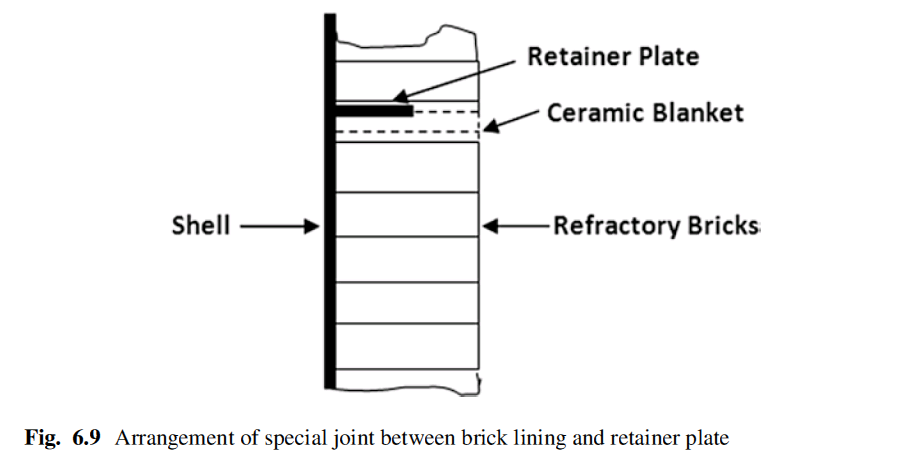
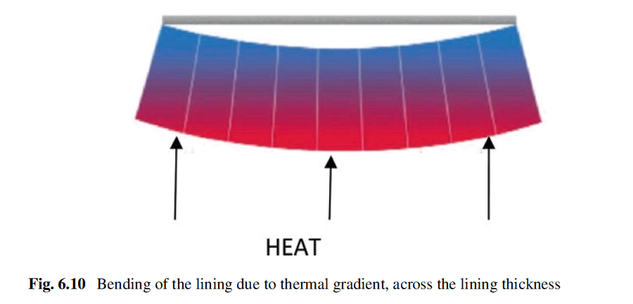
Basic Rules of Refractory Lining
Certain basic rules must be followed to get a sound lining:
(a) Refractory bricks must be laid horizontally unless the design of the lining demands an inclined lining as in the case of arch construction.
(b) The construction dimensions in the design drawing must be followed taking in consideration the dimensional tolerances. The first layer must be installed with extreme care, and then, “go ahead” must be given, checking dimensions and alignment.
(c) Brick joints must be made with prescribed mortar and joints must not be more than 2 mm thick.
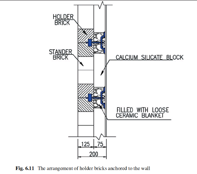
d)If due to size tolerance of the brick, the prescribed joint thickness cannot be maintained, the decision should be made to deviate from the prescribed joint thickness or to sort out the bricks.
e)If the steel wall of the furnace is not level, then the brickwork must be adjusted to the shape of the steel wall in case the deformation is not too big.
F)The brickwork must be kept clean specially the expansion joints.
G)Already laid bricks can only be aligned in the direction of the bed or vertical joint.
H)Readjustment is not possible if the mortar has started to become hard, and bricks not laid correctly must be removed, cleaned, and installed again with fresh mortar.
I)Bricks with cracks can only be used if the cracks are insignificant or it is in the rear side of the brick which will remain on the cold face of the lining.
J)The brickwork must be designed and made in such a way that no gaps or hollow spaces are formed, because the deposition of dust in the hollow space can develop an uncontrollable buildup of pressure resulting into the destruction of the lining.
Installation of Monolithics
Monolithic Refractories encompass a large category of products, namely, conven-tional castables, low cement castables, gunning and shotcreting material, and mortar. Monolithic refractories are semifinished Refractories, part of which is manufactured in the premises of supplier and the final finishing is done at application site. The monolithic refractories are, mostly, a combination of coarse aggregates and fine pow-ders, supplied as dry powder to the user. The loose powder is to be mixed with water or a specified liquid binder at site before application. Its consolidation and compac-tion, drying, and preheating ultimately influence its properties to a great extent. The application of monolithic products, of different categories, e.g., conventional cast-able, low cement castable, gunning, shotcreting, etc., is quite different. The accuracy of its installation largely influences the performance of these products.
Conventional Castables
Conventional castable products contain relatively higher percentage of high alu-mina cement and require higher percentage of water, compared to low cement cast-able. The mixing of castable with water, preferably, is to be done in a mechanical mixer. These castables can be installed by casting, pouring, or ramming. The water, to be mixed, depends upon the method of installation. Least percentage of water will be required in case of ramming. Conventional castables are also used largely for patch repairing of existing worn out lining by troweling. During installation of fresh castable over an insulating castable as back up lining, the backup layer must be suf-ficiently wetted beforehand or a waterproof coating must be made on it, to prevent the backup layer from absorbing moisture from the freshly applied castable. Similarly in the case of application of castable over an insulating board like calcium silicate, the board is to be coated with a waterproof paint like bitumen, before instal-lation of castable.
Low Cement/Ultra-Low Cement /No Cement Castables
These castables contain high alumina cement up to 6%. These are to be mixed with water, only, in a high shear mechanical mixer. Without a high shear mixing, the desired flow property will not be developed in these castables, with low water per-centage. The quality of mixer is very important in determining the water content required to get a desired level of flow. The castable mix can be installed only by vibration casting, and the intensity of required vibration may vary depending on the flowability of the castable.
recautions to Be Taken During Installation to Get Best Performance
- Castables are to be stored in a cool dry area. Castables are to be used on first-in-first-out basis.
- Mixers and tools must be clean and free of any old castable residues, cement, or foreign material, adhered to it, that may contaminate the mix and may affect the setting time and the ultimate strength of the castable.
- Only clean drinkable water is to be used for mixing castables. The dissolved contamination in water may affect the flow and setting of the castable. In cold weather, warm water can be used to raise the temperature of the mix to 15–20 °C. In hot weather, the water or castable should be cooled so the tempera- ture of the mix does not exceed 30 °C. Cold water can retard setting time and warm water accelerates the set. After placement the temperature of the casting should be maintained between 5 and 35 °C.
- The use of excess water, than required, reduces the strength of the castable lin- ing. The water quality is an important factor to influence the flow behavior of the mix, the setting behavior, and the final strength of the cast body. The recom- mended quality of the water (Table 6.1) should always be used to get the best results [6]. Castable should be mixed only long enough to produce a uniform mix (approximately 3–5 minutes). Mixing for longer time generates heat and speeds up the setting time. When a castable has been mixed to the desired consistency, it is to be placed into the forms as rapidly as possible. The recommended consistency for cast installations is the ball and hand test. A ball of properly mixed castable, when tossed 6–12 inches, should adapt to the shape of the hand when caught, but should not flow through the fingers.
- When forms are used, they should be coated with oil or grease or liquid sodium silicate, to prevent moisture loss from the castable and to aid easy removal of the forms. A form vibrator or pencil vibrator of rating 10,000 to 12,000 vibrations per minute should be used to consolidate the castable mix. The vibration removes air pockets and air bubbles and increases the density of the castable. Over vibra- tion causes segregation of the castable mix and weakens the casting. The outer casing can be drilled with 2–3 mm diameter hoes (weep holes) to aid in dissipa- tion of moisture during the drying and firing process.
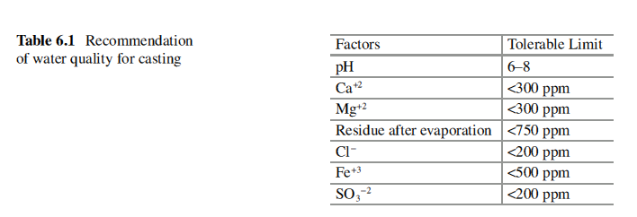
- After placement and vibrating, the castable should be cured for 18–24 hours. Allcalcium aluminate bonded castables generate heat while curing. The casting should be covered with polyethylene sheets, damp sacks, or sprayed with cold water periodically to prevent moisture loss and promote uniform curing. After the above procedure is completed, it is to be uncovered for air drying for 12–24 hours. At no time during the casting, curing, or drying process, should the castable reach freezing temperatures. In addition, at no time during the curing process should the casting be moved or shaken; vibration will interrupt the bonding process thus greatly reducing the ultimate strength of the casting.
Shotcreting
Shotcreting is most modern technique of installation of a castable, although the con-ventional castable recipe is to be modified to get the desired flow and setting property. Initially, this technique was developed and was largely used for the civil engineering construction of roadways and railways tunneling through mountainous regions. This method is, specially, useful for an installation of Refractories, to be made at a height. The basic principle of the installation of this type of product is to mix it with water to obtain a pumpable slurry, which is pumped by high capacity pump at the desired height, where the installation is to be made. The slurry is conveyed through steel pipe and rubber hose connected at the end with a steel nozzle (Fig. 6.12). At the nozzle high pressure air line is connected which sprays it to the target to be lined with cast-able. The nozzle design is very important part of the machine.
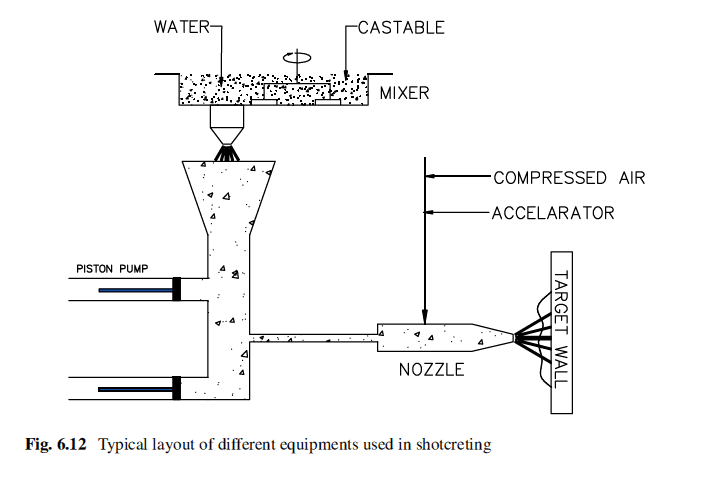
The nozzle diameter is generally 50 mm and the nozzle tip is made of special rubber. Shotcrete installation requires compressed air of sufficient quantity with sufficient pressure. A typical value is 300 kg per minute or 5–10 tons per hour at a pressure of 4.5–5.5 kg/cm2 at an ejection velocity of 45–60 m per second required for proper compaction [7–9].
Accelerator is introduced to the mixing ring by a high pressure (7 kg/cm2) low- volume dosing pump. The pump may be electric or air powered and typically capa-ble of metering the additive at a rate of 100 liter per hour. The additive type and amount may vary from product to product. The additive gels and the castable are set within a few seconds [10, 11]. The common additives used are lime, sodium silicate, aluminum sulfate, or sodium aluminate dilute solution. The extent of dilution is important to maintain proper dispersion and atomization of the additive. Mixing of the castable below temperature 5 °C may affect the gelling property of the castable and may need higher percent of additive. The adjustment of the dosage of accelera-tor is very important. The lower addition will cause slumping, and the higher addition will reduce working time and may form lamination. During the installa-tion, the nozzle distance from the gunning surface is kept 2–4 ft.
The nozzle should be kept in constant circular motion during installation. The gunning should not be done on an area that has set for more than 5 minutes. If the flow of the castable gets interrupted, the flow of dispersant is to be stopped immediately.
The installation of castable by shotcreting on a vertical wall does not require any shuttering as is used in vibration casting or pouring of castable mixes. Thus it is a very fast and cost-effective method for installation and saves a lot of manpower, although the machine is very expensive. This method is suitable for large installa-tion only and is not suitable for small patch repair, etc. It is a convenient method to line in cyclone preheaters in cement plants, which are at a height, because transport-ing and storing refractory material to that height are very difficult and sometimes unsafe.
Gunning
This method is used normally for small installation and cold or hot repairing. In this process the gunning material is poured dry in the hopper of the gunning machine, and the material is conveyed dry by the pneumatic pressure through a rubber hose to a nozzle. High pressure water is added at the nozzle tip, where the water gets mixed with the castable before it gets sprayed on the desired target (Fig. 6.13). The gunning machine can be of batch-type or continuous-type machine. The air pressure needed is 4–5 kg/cm2 for a 100 ft gun hose. For additional 50 ft length, the pressure is to be increased by 0.5 kg/cm2. The water booster pump must be able to supply 20 liters of water per minute at a pressure of 7 kg/cm2 [12, 13]. The ideal placement temperature is 15–35 °C. Pre-dampening of the castable, before feeding the gunning machine, helps in better installation. Quality of the installed lining depends on the distance, angle of nozzle with the target, adjustment of water content, and finally the skill of the operator. Depending upon the machine capacity, it can place 1–100 kg material per minute at a nozzle velocity of 30 m per second [14].
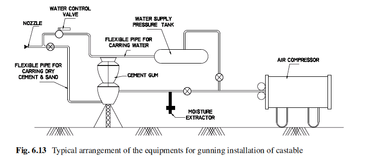
Pumping
Pumping the castable mixed with water can be done for placement of large quantity of castables [15]. The equipments required are a paddle-type mixer with a capacity of 1 ton. The high pressure piston pump is used to pump the castable slurry. The slurry is pumped through 65–75 mm diameter pipeline. A combination of hard pipe and rubber hose is used. Rubber hose should be used for the final section to distrib-ute the slurry, because rubber hose significantly increases the resistance to flow.The line diameter reduction should be done at the pump outlet with reducer section as long as possible to minimize the resistance to flow and pipe jam. The elbows used must have larger radii to reduce to minimize the resistance. Adequate personnel must be engaged to handle the hose filled with material, which is very heavy and weighs 30–50 kg per 3 m of 75 mm diameter pipe depending upon the material quality.
Monitoring and Safety
For job safety, installation efficiency, and quality of job, an audio system should be used for communication between the pump operator and placement crew. Prior to mixing and pumping the castable, the pipeline must be lubricated by pumping slurry of bentonite or any good plastic clay. The first batch of castable, to be pumped, is generally mixed slightly “wetter” than optimum. This ensures that it will pass through the pipeline with no leaks or restrictions. Once this is established, subse-quent batches are mixed and pumped at the desired placement consistency, at nor-mal pump pressure. Once pumping of castable mix begins, it is important that the pumping operation be as continuous as possible. Refractory castable, even those designed especially for pumping, can have a relatively short working time. Exposure of pipeline, conveying slurry, to the sun or hot ambient condition, can cause acceler-ated stiffening or setting. If a significant work interruption occurs or the pumping pressure increases (indicating the castable is stiffening in the line), the pipeline and pump hopper should be purged and cleaned.
Joints
Different kinds of joints need to be provided for the sound lining of castables. The joints are provided to take care of expansions or shrinkages of the refractory lining during its use.
Expansion Joints
Joints must be provided to accommodate the thermal expansion in monolithic refractories those are not supported by anchors. Size of the joint is usually com-puted by multiplying the average temperature of inside and outside of the refractory lining with the coefficient of thermal expansion of the refractory and the dimen-sions. From this value the shrinkage of the refractory due to drying and the PLC of the refractory at the operating temperature are subtracted. If the value is negative, no expansion joint is required.
Separation Joints
Monolithic refractory usually shrinks during post installation drying or when cooled after heating. To protect the lining from damage due to shrinkage, joints are pro-vided at appropriate intervals which can absorb the shrinkage. These joints are made by sectional installation of the lining or by inserting thin sheets of millboard or ceramic paper into the lining during installation. Cuts made halfway through the thickness of lining, called scoring, can also be used as a separation joint. The fol-lowing methods are used to provide expansion joints:
- Castable refractory is poured in alternating segments between the expansion joints. After the castable sets, foam styrene is fixed to both joint surfaces of the lining, and castable water mixture is poured in remaining segments
- Foam styrene of 3 mm thickness is fixed on veneer boards, and the boards are fixed firmly on the form at the required spacing so that it will not be displaced during installation. Castable is poured on both the sides of the partition to neu- tralize the pressure of the castable.
Choice of Installation Method
For a furnace or equipment construction if it is decided to use castable refractory, then the question arises that which method of installation will be the best. There are essentially four different methods by which the castable refractory can be installed, namely:
(a) Vibro-casting
(b) Gunning
(c) Shotcreting
(d) Pump casting
But the decision of the method to be used depends on the following factors:
- Location and site condition
- Environmental condition and equipment
- Volume required to be installed
- Ease and speed of installation
- Storage conditions
- Skill of the installation team
- Curing and drying requirements
- Budget
Refractories are not commodities, and the selection of proper installation method needs a careful evaluation of the detail project requirements. Any installation method may work, but the best will be the easiest and accurate one. The decision can be made considering each of the points mentioned before, e.g.:
Location and Site Condition
The important points are:
- Accessibility of the location, where the installation is to be done inside the equipment
- Height of that place from ground level
- The obstacles on the way to reach that place
- The space around for the movement of people and equipment
If the place is at a height, then it will be easier to use shotcreting or pump casting where there is no need to carry the material at that height. In that case the machine and the material can be kept at zero level.
Environmental Condition and Equipments
The points that are important here are:
- How clean does the environment need to be around the application area?
- What kind of safety measures are required?
Volume of the Refractory That Need to Be Installed
The important considerations are:
- How much materials are to be installed in how much time. If a large volume of castable is to be installed in a short time, then shotcreting or pump casing should be the choice. If a small quantity is to be installed, then casting or gunning should be a better method.
Ease and Speed of Installation
Some method of installation are much faster, for example, shotcreting installation is much faster because it does not require any former to install as is required in case of casting. Therefore the time required for fixing of the formers, greasing it, and removal of the formers can be saved. A comparison of typical time requirement for installation of castable by various techniques [16, 17] is made (Fig. 6.14).
Storage Condition
If there is no storage space available around the area of installation to keep the mixer or required equipments, then instead of vibro-casting, shotcreting will be a better method, because the shotcreting equipment can be placed far off from the installa-tion point. The material to be installed, also, will be stored, naturally, near the shot-crete machine, eliminating the requirement of space around the installation area.
Skill of Installation Team
Gunning, shotcreting, and pump casting require more trained and experienced crew members than that by vibro-casting.
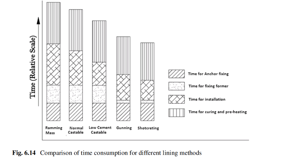
Budget
Many a times, though, the cost of the materials (considering equal properties) is the same, but the size of the project can make the difference because of wastage. In pumping or shotcreting application of 100 tons of castable, the wastage due to mate-rial in the hose pipes may not be significant but will be a very significant cost factor for installation of 5 ton material for which gunning is a better choice. The main cost-differentiating factors are equipment cost and labor cost.
Anchor
For a complete monolithic lining of any equipment, anchor system is an integral part of refractory design and largely responsible for achieving desired campaign life of the lining. The anchor system includes the selection of anchor construction mate-rial, anchor design, anchor spacing, and the fixing of anchors. The anchors can have multitude of sizes and shapes.
Anchor Construction Material
Metal anchors are used where the service temperature does not exceed 1200 °C. At high temperature the mechanical strength of the metal decreases, and it is corroded fast. Different grades of alloy steels are used for making anchors, and the choice of material of construction depends upon the actual temperature the anchor is to with-stand. In selecting the anchor material, the temperature of the tip of the anchor embedded in the lining must be taken into consideration. This should be predicted from the temperature profile of lining. Table 6.2 shows the steel grades and alloys, suitable for different temperatures [18–20].
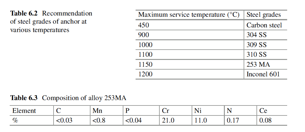
Anchors are made normally of steel rod and plates. Above 1200 °C, ceramic anchors are used, which are basically refractory shapes of alumino silicate quality, with Al2O3 content varying from 30% to 80% depending upon the application temperature.
During selection of the anchors, the temperature profile across the lining is a very important factor to be taken into consideration [21]. Higher operating temperature can lead to carbide precipitation in the metal that changes the original properties of the metal, causing rapid oxidation and premature failure of the anchor and lining. The atmosphere prevailing in the furnace can change the temperature profile in the lining. It has become more important today because of more and more use of alter-nate fuels. The high nickel content (without any special additive in the alloy) makes the steel highly sensitive to sulfidation [22].
Reducing, sulfurous, and nitriding environment can severely affect the metallic anchor, and care must be taken in the choice of metal alloy. This led to the develop-ment of new alloys that contained specially added components. Additional corro-sion resistance is provided by the rare earth elements (e.g., cerium, lanthanum). In the environment of a cement plant, the first micro alloyed commercialized steel grade 253MA is found to work better than SS 304 and SS 309. The composition of 253MA is given in Table 6.3 [18, 19].
Anchor Shape and Size Design
Flat anchors, made from steel plates, are cheap, simple to manufacture, and readily available. Therefore these anchors are often used, but those have some major disad-vantages. The surface area of flat anchor is more, compared to rod anchor with similar mechanical strength. Because of higher surface area, corrosion rate is higher in flat anchors [19]. The steel rod anchors are mostly in the shape of “V” with the angle of 60 degree. The arms of the “V” are sometime twisted to provide an extra surface area and better holding. The arm lengths of the “V” are normally 25 mm less than the lining thickness. Sometimes the arms of the “V” are of different lengths to prevent spalling in layers. The selection criteria of diameter of the anchors are shown in Table 6.4.
The said anchors are suitable for lining up to 230 mm thickness. Different designs of anchors are shown in Figs. 6.15 and 6.16. During use at high temperature, the metallic anchors will expand, and if the space is not provided for expansion, the lining will develop crack. The plastic caps are put on the tips of the “V” arms, and the bitumen paints are brushed on the anchor rods. At high temperature, these will burn out, leaving a space for the expansion of the anchors.
For dense monolithic linings with thick cross sections (greater than 230 mm), the use of pre-fired refractory anchor is the preferred method of anchoring the structure. Ceramic anchors have several advantages over other types of anchoring systems. They have more holding power than metal anchors due to their design and greater
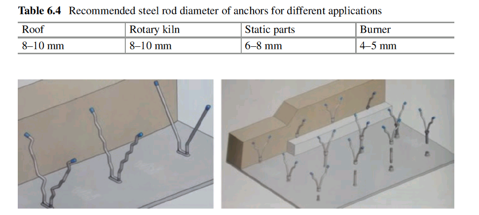
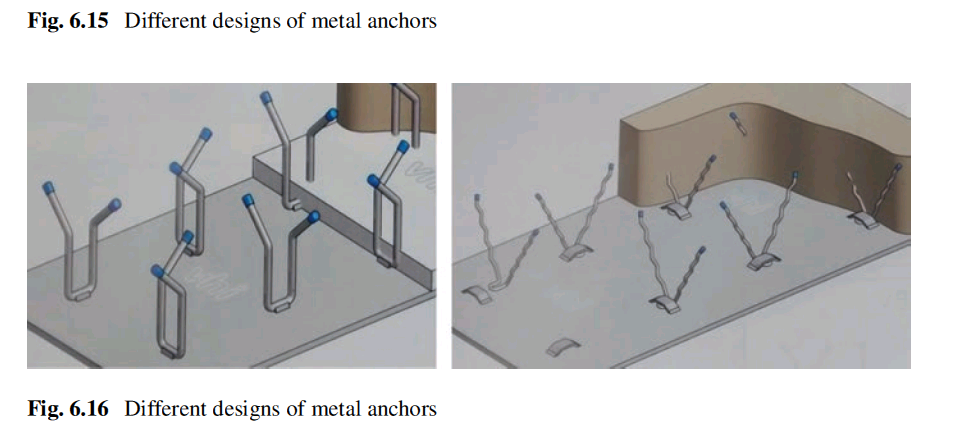
surface area. They also extend through to the hot face providing extra retention of the lining. Also being ceramic material, those can withstand much greater tempera-tures and tougher atmospheric conditions than standard metallic anchors.
Fixing of Metal Anchors
Quality of fixing of anchors on metal shell of the furnace or equipment determines the soundness of installation. The whole load of monolithic refractory is transferred on the anchors. The anchors must be able to hold that load for long duration at a high temperature. Therefore the welding joints of the anchors on metal shell of the furnace must be very sound, and it is to be tested by hammering the anchors after welding.
In some design the anchors are not fixed rigidly on the metal shell but are fixed through a support (Fig. 6.17) so that it remains free floating and can have movement in three dimensions to take care of any movement of refractory lining at high tem-perature. The anchor support should be in the shape of inverted U with tips bent 90 degree and welded upon the metal shell.
The support diameter should be 2 mm more than the anchor diameter. V anchor should be positioned at the middle of the support and just tack welded to the sup-port. The welding should not be rigid. It should be such that welding can be broken by hand. After fixing the anchor arms should be coated with bitumen paints or plas-tic tape to create provision for expansion.
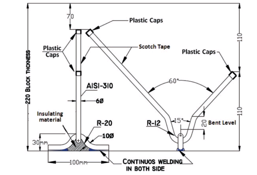
Fig. 6.17 Design of floating anchor
Fixing of Ceramic Anchors
Ceramic anchors cannot be welded like metal anchors and are fixed to the vertical metal shell or roof of the furnace or equipment through metal holders of different designs. The metal holders and clips must be able to withstand the load of the lining. Some of the designs of the holders and anchor bricks are shown in Fig. 6.18. The metal holders hang from the steeI section beam as shown in Fig. 6.18b. In case of fixing ceramic anchors on vertical wall, C-clips are mostly used (Fig. 6.18c).
Spacing
- The spacing and orientation of the anchors are also very important. The following factors determine the spacing between anchors:
- Strength of anchor
- Strength of refractory Thickness of the castable Furnace operating temperature
- Position of the lining(vertical, horizontal, inclined) Lining shape
- Existence of pressure Method of installation
- Mechanical movement of the furnace or related equipment and the external force on furnace lining
The spacings between the anchors can be determined in two different ways:
- Considering the tensile strength of the support or anchor
- Considering the strength of the Refractory
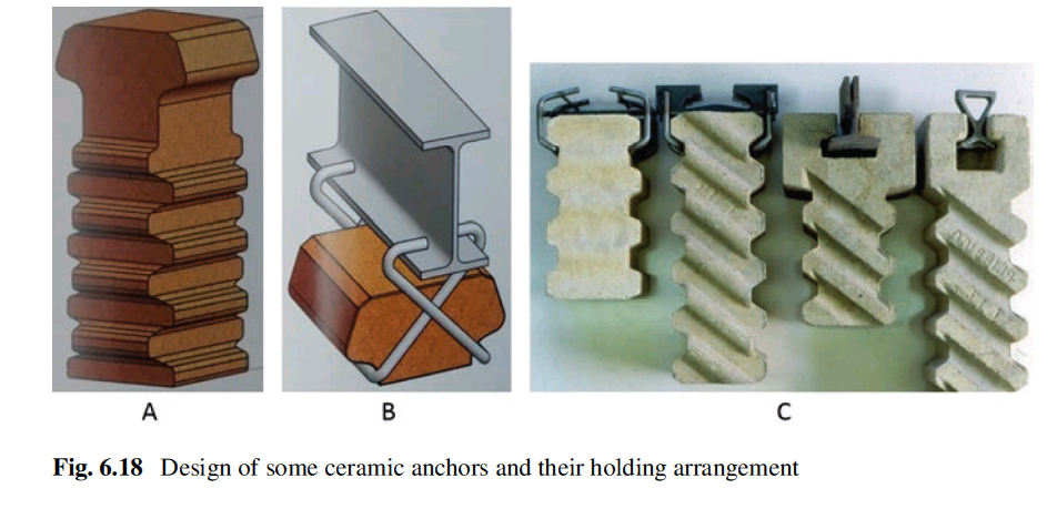
Support Spacing Based on Strength of Anchors
Spacing between the anchors can be calculated on the basis of the strength of anchor at the operating temperature and the weight of the refractory that are supported by the anchors.
- Horizontal lining (ceiling) in single layer
If t1 is the ceiling thickness, la = the spacing between the anchors, d1 = the bulk density of the Refractory lining, a = the area of cross section of the support, σm = the permissible tensile stress of the support material at operating tempera- ture, then
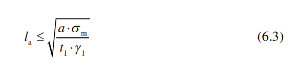
- Support spacing in a three layer refractory lining If the first, second, and third layer thicknesses are t1, t2, and t3 and their bulk densities are d1, d2, and d3, then
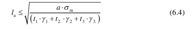
Support Spacing Based on the Strength of the Castable
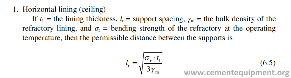
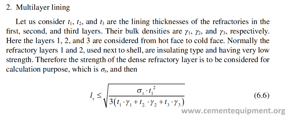
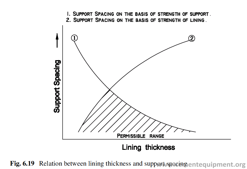
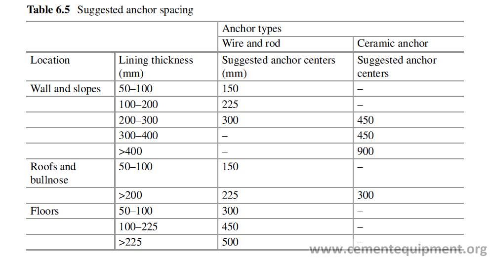
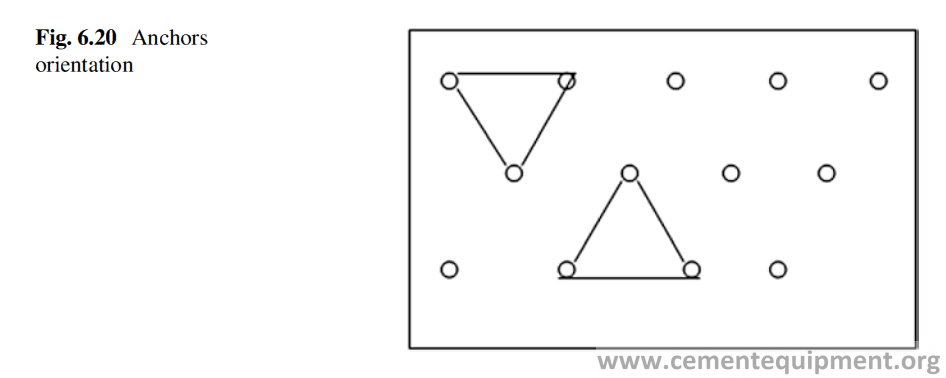
The support spacing calculated separately based on the support strength and the anchor strength is related to each other as shown in Fig. 6.19 [6, 23]. Table 6.5 gives the general norm of selection of anchors and spacing.
The anchors’ positions are kept in a regular manner, and the orientation of the anchors is made in such a way that two adjacent anchors in one row form an equi-lateral triangle with the nearest anchor in the other row (Fig. 6.20).
Drying and Preheating
This is one of the most important steps in Refractory installation. The part of the water used during installation of castable remains within the lining. In brick lining also, some physically absorbed moisture remains, and the extra moisture comes from the mortar used. The internal moisture inside the lining will get evaporated and removed during the operation. But the main idea of preheating is to remove the physically and chemically bound moisture in the castable or in the brick lining slowly and in a controlled manner. Fast removal of water from the system may develop crack in the refractory lining and may cause explosion in castable lining. Besides the moisture removal, the other major function of preheating is to achieve a thermal equilibrium to stabilize the whole system, including refractory lining. In case of rotary kiln, especially, because it is a moving structure, the bricks, of the lining, rearrange themselves during the preheating period accompanied by its move-ment and the lining attains stability. In a cement plant, where several thousand tons of refractories are used to line different equipments, this thermal equilibrium is to be attained slowly. The plant runs smoothly once it is established. In cement plants, drying and preheating of refractories in all the equipments, e.g., cyclones, kiln, TAD, hood, and cooler, are needed. The hot air generated for drying purpose must have sufficient volume to create turbulent flow for more efficient heat transfer. The additional burners very often are required to be installed in kiln inlet or preheaters to increase drying efficiency. Refractory lining, very often, consists of various quali-ties with different drying characteristics. During the drying of such lining, the heat-ing curve, for the material with lowest permissible heating up curve, is to be chosen. It is widely accepted that truly effective means of drying out Refractories, is, to deploy some form of convective heat source, passing large volume of hot gases over the refractory surfaces.
This creates a “scrubbing” action on the object under drying, which hastens the heat transfer process through the refractory thickness. It ensures that both physically and chemically bonded moistures are rapidly and safely driven off.
The burners, with very high turndown ratio (100:1), are used enabling tempera-tures to be accurately controlled at all stages from 80 to 1000 °C. The burners with fully adjustable output generating up to 2.5 million kilocalories per hour through hot gases, when connected to its combustion air fan, are used. These hot gases are emitted at an outlet velocity of some 150 m per second [24]. This creates a turbulent atmosphere, promoting highly effective scrubbing action necessary to drive off moisture rapidly. The quick conversion of residual moisture to steam may cause explosive spalling, if the lining material is very dense and impermeable.
Besides the drying, slow preheating is a requirement to stabilize the refractory lining. Refractory lining always experiences more abuses on its hot face rather than cold face. When preheating starts, the hot face receives the heat, first. Heat is then conducted through refractory lining from the hot face to the cold face.
When preheating starts, temperature of refractory rises much faster than the steel shell. As temperature rises, Refractory tries to expand, but the steel shell, behind, not yet heated up, resists the expansion of the refractory lining. Under such condi-tion, Refractory at the hot face will experience a high compressive stress. Refractories readjust themselves to mitigate the causes responsible for the development of such stresses.
In a similar way, during shutdown, when the heat source is put off, the furnace is on cooling; the Refractory hot face starts losing temperature fast, by radiation and convection of heat. As the refractory hot face is becoming cool, it will try to con-tract, but the refractory face in contact with steel shell, still hotter, will not allow it to contract, and thus the hot face will experience a strong tensile stress. Stresses developed inside the refractory lining, which appear as a result of rapid temperature changes, can be calculated [25–27].
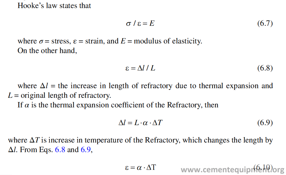
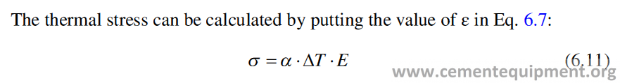
However, a slow temperature change does not give an effect of thermal stress growth, because of stress relaxation effect [26–28]. The stress disappears with the course of the time according to the equation,
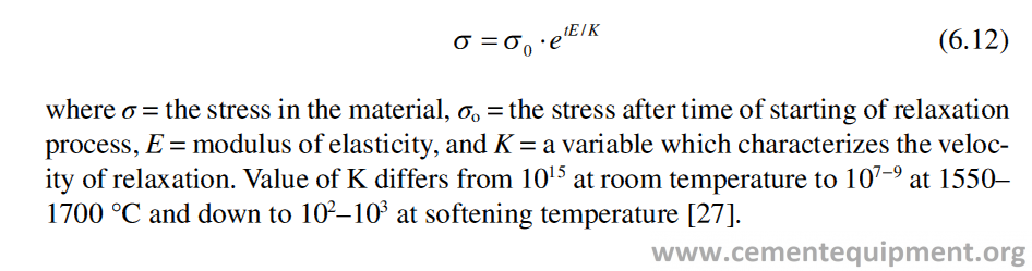
Preheating of Bricks
The slow preheating of the brick lining is done for stress relaxation at high tempera-ture. Preheating of the kiln is done following the heating curve shown in Fig. 6.21 [29]. In case of complete new lining, the time-temperature schedule will be longer than that in the case where a repairing or partial lining is done. In case of high alu-mina refractory lining, the time required for heat up is lesser because of lesser ther-mal mass. The preheating can be done faster also because lower thermal expansion coefficient of high alumina refractories develops lesser thermo-mechanical stresses. Moreover the stress relaxation starts at lower temperature in case of high alumina refractories. In case of basic refractories, because of higher thermal expansion coef-ficient and onset of stress relaxation at higher temperature, it needs to be preheated at slower rate.
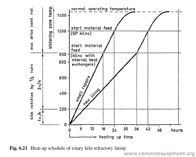
Too fast heating of the refractory lining can cause high compressive stress on the working surface of the brick because the expansion occurs on the surface only when the brick inside or steel shell still at much lower temperature. This can be identified by typical convex surface of the brick after cracking. Figure 6.22 shows a high alu-mina brick lining in the upper transition zone cracks due to fast preheating [30].
The fuel used for preheating can be either gas or liquid fuel. Basic refractory lin-ing is sensitive to reaction with water vapor, generated from the evaporation of moisture in the lining, as well as the water from the combustion product of fuel (natural gas or oil), especially in the temperature range 60–295 °C. This is a critical temperature zone, where the MgO in the basic bricks tends to react with the water vapor to form Mg(OH)2. The reaction MgO + H2O = Mg(OH)2 is associated with a volume expansion and causes crack in the lining. This phenomenon can happen when the water vapor condenses on the Refractories. In practical application, when natural gas or oil is used for preheating, the care is to be taken to pass the critical temperature range 60–295 °C as quickly as possible to prevent hydration reaction of basic lining to occur [31]. The reaction tendency decreases with increasing temperature.
Preheating of Castable
The main purpose of preheating of the castable lining is to remove the water from the system. Castable sets and gets hard because of the formation of different hydrated compounds of calcium aluminates. These hydrates, e.g., CaO.Al2O3.10H2O (CAH10), CAH6, C3AH6, and AH3, decompose when heated. The decomposition temperatures of these hydrates are different.
The water gets released during the thermal decomposition of the hydrates and is to be removed slowly. The fast preheating of the castable lining may lead to sudden
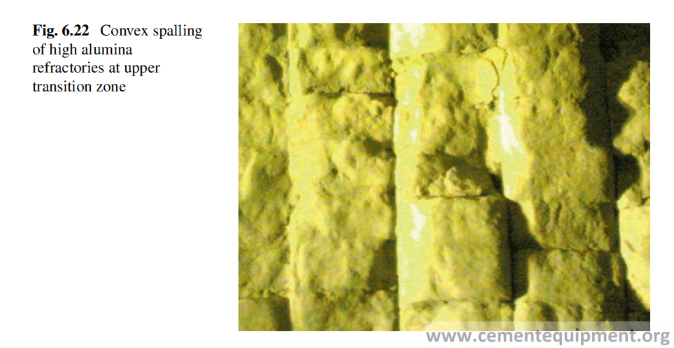
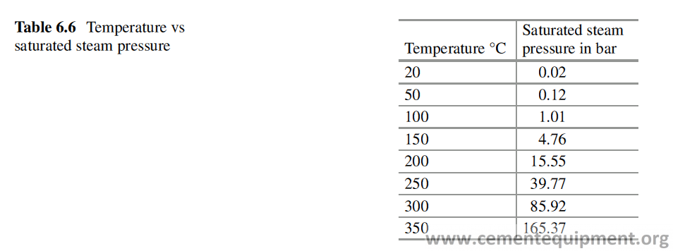
formation of steam inside and generates a very high steam pressure (Table 6.6) [32]. This may cause crack, even explosive bursting of the lining. This is more relevant and important for low cement castables, which, in general, have low permeability to hinder the liberation of water vapor on heating. The water remains in castable both as physically bonded and chemically bonded water. The physical water gets removed within 200 °C, but the chemically bonded water gets dissociated at a temperature of about 550 °C. The higher the content of cement in the castable, the more the amount of chemically bonded water. The relationship between the heat-up rate of a castable lining and the percentage of the elimination of moisture depends upon the lining thickness. The addition of organic fibers in castables helps a lot for easy removal of water vapor formed in preheating. Whatever is the thickness of the lining, it is the surface of the lining that is immediately affected by the initial heating. The castables generally have low thermal conductivity, and therefore the lining cold face is pro-tected by the thickness of the lining. One sided heating actually makes the thing more complex because of continuous heat and mass transfer, continuous chemical dehydration reactions, change of thermal conductivity of the lining with continuous removal of moisture along with internal changes in steam pressure and development of mechanical stresses.
Experiment shows that a thickness of 100 mm from the heating surface gets affected by the initial heating up. Too slow rise of temperature is safe, but uneco-nomic and too fast rise of temperature may cause explosion and crack in the lining to damage it. In the most desirable heat-up schedule, the time vs temperature and the time vs moisture removal curve should go very close. The type of castable refractory has got a bearing on the temperature rise and the moisture removal per-centage. Below given is a heat-up curve (Fig. 6.23), which is safe and efficient and is commonly applicable to different types of castables [6].
The castable lining, after the shuttering is removed, should be allowed to get air dried at ambient temperature for 24 hours before the starting of preheating by hot air.
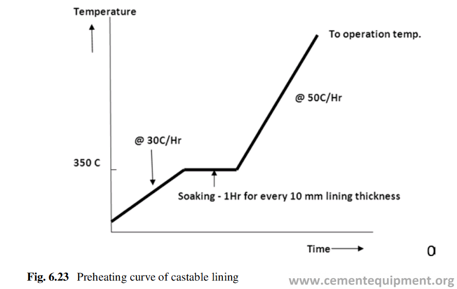
Carbonation
If the refractory lining, especially made of the conventional or insulating castables, is left without preheating for long time, it starts deteriorating because of efflores-cence and carbonation reactions.
Soluble oxides, in castable, from used raw material or water, leading to diffusion of Na ions in the solution, react with aerial CO2 to form sodium carbonate. This sodium carbonate reacts with calcium aluminate hydrates of the castable to form CaCO3 as shown in reactions below.
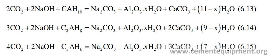
Although the equation shows sodium carbonate as anhydrous material, it remains associated with 1,7, or 10 molecule of water of crystallization which varies in terms of density (Table 6.7) [33].
Depending on the quantity and occurrence, it can destroy the castable structure because of volume expansion as evident from Table 6.6. Formation of Na2CO3.H2O can cause surface efflorescence (Fig. 6.24) without affecting the structure but with loss of strength of the castable.
In absence of alkali, the aerial carbon dioxide reacts with calcium aluminate hydrates to form calcium carbonate and alumina hydrates, as per the reactions below [34].
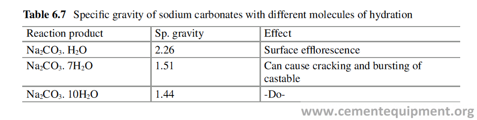
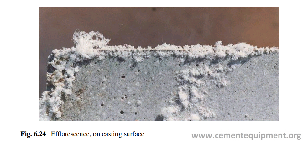
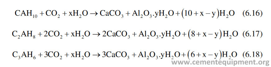
The rate and extent of the reaction depend upon the type of calcium aluminate hydrate with the order CAH10 > C2AH8 > C3AH6.
- The practical observations of refractory castable reveal the following tendencies:
- Carbonation occurs easily in lightweight castables, but hardly at all in dense castables.
- Carbonation occurs easily in not dried products and hardly at all in dried castables.
- Carbonation occurs easily in an environment with high temperature and humidity.
- When not dried products are exposed to rain, the carbonation rate is highly accelerated.
Therefore the lining made with conventional or insulating castables should not be allowed to remain without drying and preheating for long time, especially where the humidity and temperatures are high [35]. The drying and preheating of the cast-able make it stable, and it does not deteriorate further.
Refractory Performances and Mechanism of Damages
Introduction
Refractory performances in cement industries, similar to its performances in other process industries, depend largely on many other factors, besides the quality of Refractories as shown in Fig. 7.1. The diagram clearly shows that quality of Refractory, quality of its storage and installation, and kiln’s mechanical features and operating condition, e.g., chemistry of the feed to the kiln and the thermal parame-ters, play a very important role in deciding the Refractory performance. The selec-tion of right kind of Refractory also is very important, and selection sometime is made by the user by providing a specification, and sometimes the quality is sug-gested by the refractory supplier, and in some occasion it is decided jointly.
It clearly indicates, that, factors, those govern the performance of Refractories, are mostly in control of the user of Refractories, rather than in control of supplier of Refractories. The best Refractories also cannot provide desired performance, if the installation is improper or the operating conditions prevailed are not friendly to Refractories. The storage quality of the Refractories is particularly important for basic bricks and monolithic refractories. The influence of the chemistry of raw meal and different thermal and mechanical parameters of the kiln operation on the refrac-tory performance are shown in Fig. 7.2 [1, 2].
Experience shows that in the overwhelming majority of cases, there is never one, definite cause but instead a “chain of events” that lead to the “failure.” In other words, there were multiple variables that impacted the refractory material in service [3].
The refractory material is only one component in the overall design of process equipment and industrial furnaces. It is sensitive to (and influenced by) time, tem-perature, and operational factors. The experiences say the culprit will likely be one (or a combination) of the following:
1-Improper combustion (fuel, ratios, atmospheres, flow, etc.)
2-Flame impingement (flame geometry, improper setup, etc.)
3-Improper furnace controls (PLC’s controls, circuitry, thermocouples, dampers, etc.)
4-Operational change (cycling, throughput, load, etc.)
5-Operational procedures
6-Maintenance practices
7-Shell and lining movement due to a difference in expansion rates
8-Mechanical stresses
9-Environmental factors
10-Feed
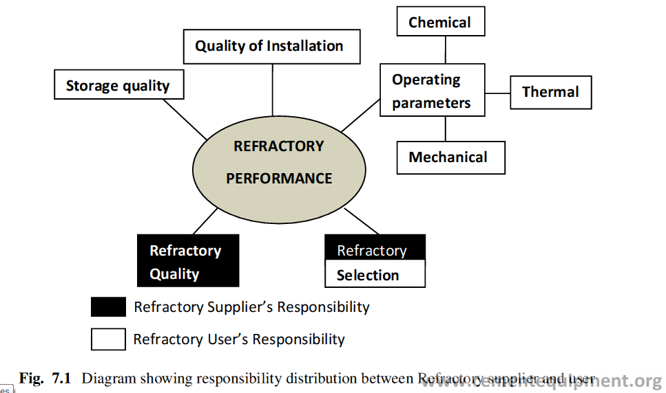
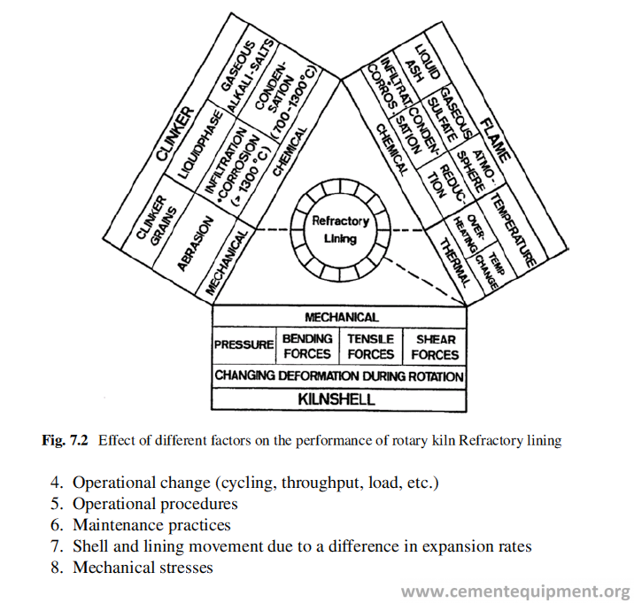
From a refractory perspective, all these factors have an impact on refractory and can cause:
- Excessive temperatures (shrinkage, etc.)
- Hot spots
- Excessive cracking due to spalling, thermal shock (a result of temperature fluc- tuations), mechanical shock or compressive forces, linear change, bending, etc. Structural issues
- Erosion and abrasion of the refractory lining Anchor failure
- Failure of the steel shell which supports the refractory Mechanical damage
All of the above factors can cause the refractory material to end its campaign life sooner than originally expected. As variables do change, the selection of the refractory used may need to be reconsidered. If there are new variables that the prod-uct must face, then an upgradation or change in refractory lining may be warranted. Statistical analysis of the refractory-related problems and performances, on a large number of cement kilns worldwide, shows (Table 7.1) the frequency of problems occurring in different application areas of the kiln system [4]. The table also shows the effect of different factors, e.g., thermal load, thermal shock, clinker liquid phase infiltration, salt infiltration, redox condition, mechanical stress, and ring formation on the refractory performances in different major areas of the total kiln system.
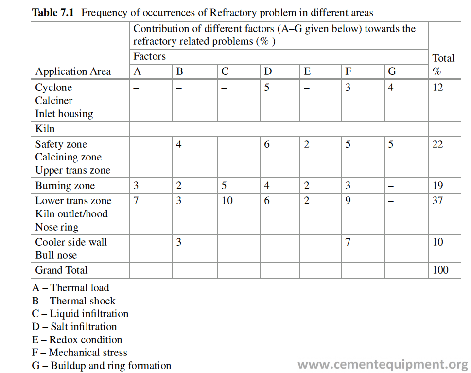
The most vulnerable area in the rotary kiln is the burning zone, where the Refractory wear-out is much more than that in other areas of the kiln, because of higher temperature, cyclic temperature fluctuation, and the presence of clinker liquid phase. Although the factors responsible for refractory performances are shown as discreet entities but they are all interdependent and overlapped with each other. Analysis of the Refractory wear-out and failures in the rotary kiln alone shows that about 35% of the problems are because of reasons thermo-chemical in nature, 28% due to thermo-mechanical in nature, 19% due to thermal overloading, 3% due to redox reactions, and another 15% attributable to reasons other than those mentioned here.
Thermo-chemical Effects
Primarily kiln temperature is the most important operational parameter to decide the refractory performance, and higher operational temperature initiates more problems with refractory lining.
Rate of chemical corrosion increases exponentially with rise in temperature, and similarly the thermo-mechanical stresses also increase with temperature. Therefore to get clinker of desired quality, optimization of operational tempera-ture is very important, and achieve that, control of composition of feed material is most essential. Some very proven tool to control the feed chemistry vis-à-vis the firing temperature of the kiln, is different cement moduli which are given in tabular form (Table 7.2).
At high temperature, especially, the refractories in the burning zone of the kiln, reacts with different input materials in the system through the feed and fuel. The reaction takes place in solid-solid, solid-liquid, and solid-gas phases which ulti-mately causes the refractory wear and reduces the campaign life of Refractory lin-ing. The mechanism of degradation of Refractory varies with the type of refractory and its place of use. The reactions responsible for degradation of refractories are mainly due to solid-liquid and solid-gas phase reaction.
The chemical impurities enter into the kiln either through the raw meal or through fuel and take part in different chemical reactions with the refractory lining at high temperature. The increasing use of alternative fuels in cement manufacturing aggra-vates the situation and puts lot of chemical stress on refractory lining [5–9]. Table 7.3 [10, 11], shows the different impurities enter into the kiln system and their sources. The reaction of refractory and the liquid phases, formed in the kiln during clinker-ization process of the raw meal, can be divided into three different stages for a better understanding of the reaction, namely:
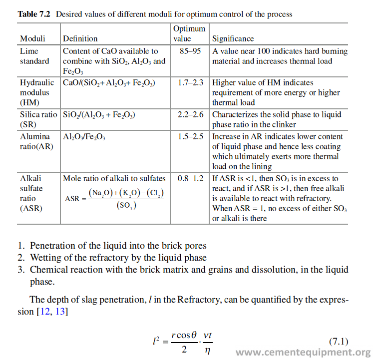
where r = pore radius, ν = clinker liquid surface tension, θ = contact angle of clinker liquids and the refractory, η = viscosity of the liquid phase, and t = time.
The penetration of the liquid phase can be suppressed by increasing the viscosity or the contact angle and the decrease of the surface tension of the liquid phase. The values of the variables, i.e., η, θ, and ν, change as the reaction progresses. The reaction products can be solid, liquid, or gas. The reaction products may stick to the solid surface to form a barrier for further attack of the liquid phase, or if the reaction products are liquid and gas and get removed from the surface of reaction easily, the solid surface is easily available for further reaction. The reaction may progress very fast when the reaction products are soluble in the liquid phase. The corrosion rate is the function of many factors including temperature, solid-liquid interface composi-tion, and liquid density, viscosity, diffusivity, and degree of turbulence.
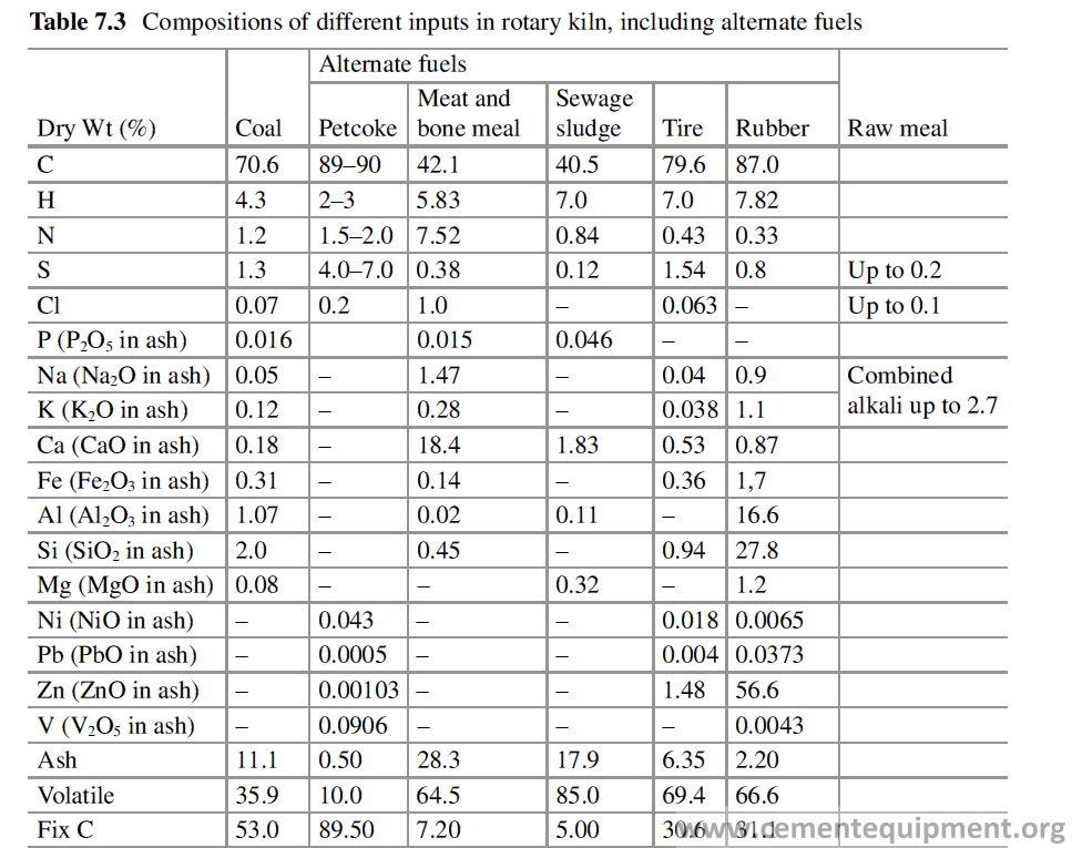
Aluminosilicate Refractories
Aluminosilicate Refractories are used mainly in the preheating and calcining zone of the kiln and also used widely in the burning zone of the kiln, especially in the kilns with diameter below 5 m. The damage of the high alumina refractory in cement kiln burning zone may be due to chemical corrosion of the refractories by reaction with CaO, the liquid phases in the cement clinker, alkalis, etc. Considering that the cement raw mix contains mainly four oxides, i.e., CaO, SiO2, Al2O3, and Fe2O3, the liquid phase starts appearing at 1338 °C, i.e., the eutectic point of the C-S-A-F system.
At this eutectic temperature, the liquid which is formed has got a chemical analy-sis of CaO (55%), SiO2 (6%), Al2O3 (23%), and Fe2O3 (16%). This liquid can take more SiO2 in solution, and therefore it can attack the refractory containing SiO2 and can corrode it, taking it into solution. The impurities in the raw mix like MgO, Na2O, K2O, and SO3 can further bring down the liquidus to 1280 °C and make it more corrosive.
Normally, the liquid phase in the cement clinker in burning zone is maintained between 23% and 30% [14, 15]. This liquid penetrates through the brick pores and cause densification of the refractory, which increases its modulus of elasticity and makes the refractory brittle.
Moreover, the densification changes the physical properties, e.g., thermal expan-sion coefficient of the densified portion of the refractory from the rest of the brick, and during heating and cooling of the bricks, crack develops because of dissimilar α value.
As shown in Eq. 7.1, the viscosity of the liquid melt is a very important param-eter to determine the extent of infiltration of the refractory by the liquid phase, and the lower is the viscosity, the more will be the infiltration. The viscosity decreases rapidly with temperature rise. It is found that increase of temperature by 93 °C reduces viscosity of the clinker liquid phase by 70% [16]. Presence of MgO, alkali sulfates, fluorides, and chlorides in the clinker also helps in reducing the viscosity. For example, a regular clinker liquid phase has got a viscosity of 0.16 N.s/m2 which is reduced to 0.05 N.s/m2 in presence of 2% SO3 in the clinker [17]. Free alkali and phosphorous increase the viscosity of the melt but are offset by presence of MgO and SO3. The liquid phase viscosity is found to increase linearly with increasing alumina/iron ratio.
Another important property of the liquid is its surface tension which indicates its ability to wet the refractory surface. A liquid phase with higher surface tension has lesser ability to wet the refractory surface and to corrode it.
Interaction with Alkalis
Alkalis enter into the kiln system through the raw meal and the fuels, especially through the alternative fuels (Table 7.3). Then the alkali gets circulated inside the kiln and gradually its concentration increases (Fig. 7.3). The alkali gets vaporized from the burning zone and is carried to the calcination zone, where it gets con-densed and again is carried to the burning zone with the feed and gets evaporated and this cycle continues.
The mechanism of destruction of refractories on interaction with alkalis can be shown schematically in Fig. 7.4. The alkali in the kiln combines with chlorine and oxides of sulfur to form alkali chlorides and sulfates, and their mixtures form low- melting liquid phases reacting with Refractories at high temperature, as shown in Table 7.4.
These liquids get infiltrated inside the pores of the refractory and form a densi-fied layer, with altered thermal properties, which during heating and cooling forms crack at the junction with unaltered layer causing gradual destruction of the lining [17].
The alkali salts in the vapor phase get infiltrated the brick pores and get con-densed inside the pores of the bricks in colder zone. Thermal expansions of these salts (Table 7.5) are much higher than the refractory body, and during heating and cooling, they exert pressure on refractories causing cracks [18–23]. These salts and the liquids get infiltrated in the brick pores and alter it physically to reduce its MOE and to change its coefficient of thermal expansion to make the refractory more brit-tle and prone to thermal spalling.
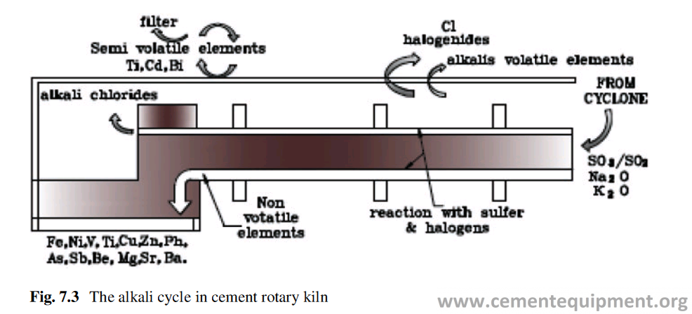
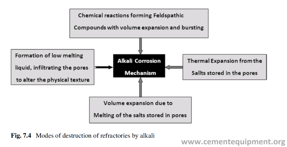
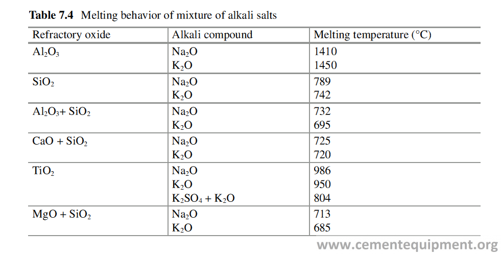
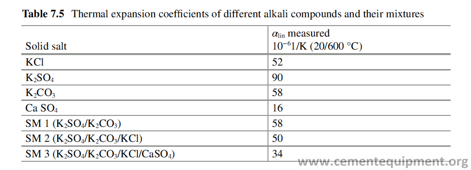
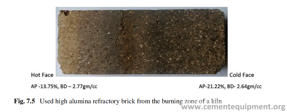
The photo (Fig. 7.5) of the used high alumina bricks from the burning zone of a cement rotary kiln shows the color variation from cold face to hot face. The porosity and density of the hot face and cold face are shown in the figure.
There is a difference in the density of the solid and molten alkali salts, accompa-nied by a volume change (Table 7.6). As a result when the refractory lining, contain-ing the solid salts deposited in the pores, is heated and cooled, the melting and solidification of the salts exert a pressure on the refractory body, and repetition of this phenomena causes crack to the body.
The alkali salts react with alumina, silica, and mullite at high temperature with formation of different feldspathic compounds associated with large volume expan-sion which ultimately destruct refractory (Table 7.7). If alkalis are very high and are not balanced by sulfur, it will be very difficult for them to exit the kiln. The alkalis will therefore continue to recirculate within the kiln/preheater system and increase the probability of kiln rings and preheater buildups. Clinker quality may suffer because free alkalis can enter into solid solution within the clinker minerals affect-ing their reactivity.
Interaction with Sulfur
The major source of sulfur in the clinker manufacturing is petroleum coke and coal from some origins. The lower price and higher calorific value have made petcoke a very attractive fuel for cement manufacturing. The obvious effect of using petcoke as fuel is the disturbance of the alkali/sulfur ratio, and the raw meal formulation needs to be changed to maintain the desired ratio.
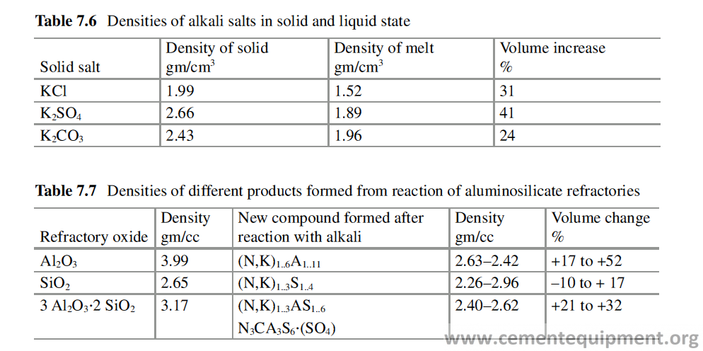
Once the amount of alkali sulfates that can be produced is exhausted, excess sulfur needs to be removed from the system with free lime as calcium sulfate which is promoted at higher oxygen levels. Most plants burning petcoke have severe sulfur buildup problems revealing the sulfur is not being adequately removed from the system. The most obvious effects of the high concentration of sulfur are in the amount and hardness of the coating, sulfur ring formation, and tower buildups. All these contribute to a reduction in gas flow, which, without adjustment, causes reduced oxygen levels and a worsening effect. It is estimated that a minimum of 15% flow is required to the bypass to reduce the sulfur compared to only about 2% to reduce chlorides to a “refractory” acceptable level. The removal of the buildup by mechanical means damages the refractory lining. The prevention of buildup requires control in alkali/sulfur ratio and oxygen level, and minimum availability of chlo-rides helps to prevent buildup [24]. The reducing condition in the kiln increases the volatility of sulfur, and excess oxygen decreases it.
The variation of the fuel compromised with the stability of coating on the refrac-tory lining and the life of the refractory lining in transition and burning zone is directly proportional to the stability of the coating. Every instance the coating is dropped from an area of lining, the bricks are subjected to an instant thermal shock, resulting in compressive stress shock wave. Also when the coating falls, the brick is directly exposed to the process heat and environment. This allows the volatiles (sul-fur/alkali) to condense on the surface and penetrate deeper into the brick. Due to the higher temperature at the brick hot face and the additional elements available to react with, a liquid phase will result on the brick surface and destroy the brick prop-erties in all affected areas. Upon repeated exposure the liquid phase will penetrate deeper into the brick. It is also possible that if a liquid phase is formed and then quenched, a slick glass layer will form making the surface unable to adhere to fur-ther coating.
Because of higher alkali percentage in the raw meal, where petcoke is used as fuel, the normal high alumina refractories in the burning zone are prone to alkali attack and are not very suitable. In those kilns phosphate bonding to high alumina refractories imparts a lower permeability to the refractory and reduces the alkali attack. Moreover, petcoke also contains some heavy metals like vanadium and nickel which reacts with Refractory at high temperature, and phosphate bonding retards those reactions. Thus the phosphate-bonded high alumina refractories are a better choice over the normal high alumina refractories in the burning zone in the rotary kiln using petcoke as fuel.
Interaction with Chlorides
Chloride contained in the raw mix as well as in the kiln gas and water vapor (in the kiln gas) increases the volatility of the alkalis. If chloride is very high in the system, it will first combine with all of the alkalis present forming alkali chlorides which will recirculate in the kiln and increase the probability of buildups in the preheater [24]. Any remaining chloride will then combine with CaO to form CaCl2 which has a very low melting point (770–780 °C). This will make the hot meal extremely “sticky” at this temperature and increase the chance of buildups higher up the pre-heater. Chlorides also form eutectic mixtures with sulfates of potassium, sodium, calcium, and magnesium. These eutectic mixtures have melting points much lower than that of the pure compounds, further increasing the likelihood of rings and buildups. Above 0.015%, in the raw meal, chloride recirculation is so strong that blockages in the preheater are eventually inevitable.
Interaction with Vanadium Oxides
Vanadium is also an impurity which remains in fuel oil and petroleum coke. Vanadium reacts with oxygen to form vanadium oxides, V2O5, which melts at 690 °C. When the availability of oxygen is less, V2O3 and V2O4 are also formed, having melting points 1970 and 1634 °C. The vanadium oxide V2O3 reacts with Na2O to form Na2O·3V2O5 and Na2O·6V2O5. Melting temperature of both these materials decreases as the partial pressure of oxygen increases [25].
Presence of small amount (0.1% by weight) of V2O5 can cause grayish green coloration to aluminosilicate refractories. The combustion products, V2O5 and NaVO3, react with aluminosilicate refractories including insulation. Fibrous refrac-tory insulations are more prone to this reaction because of its larger surface area than dense refractory products.
Vanadium pentoxide forms a low-temperature eutectic 650 °C with Al2O3. In comparison, the eutectic temperature of V2O5 and silica is 649 °C. Mullite exposed to sodium vanadate may decompose according to the following reactions:
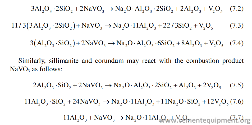
Vanadium pentoxide in the combustion ash will reduce the amount of free Na2O available to react directly with the refractory because the V2O5 reacts with Na2O to form sodium vanadate. However, sodium vanadate, acting both as a flux and a min-eralizer, may react with the Al2O3-SiO2 compositions at much lower temperatures and generate more liquid phase than would either Na2O or V2O5 alone. Indeed, in the presence of both Na2O and V2O5, nepheline is formed at 800 °C, whereas it is not formed even at 900 °C when Na2O alone is present. Albite, which also is not formed in the presence of Na2O alone, is formed if NaVO3 is present with Na2O because of the powerful mineralizer action of NaVO3.
The binary system CaO-V2O5 has a series of eutectics and intermediate com-pounds (Fig. 7.6).
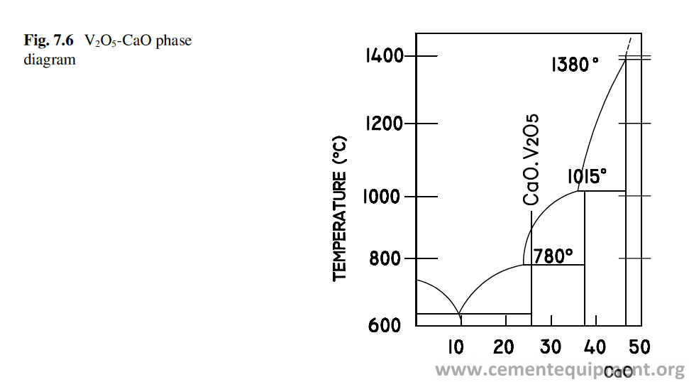
The castable refractories contain the hydrates of the different calcium aluminate phases like CA, CA2, etc. which may react with sodium vanadate at high temperatures.
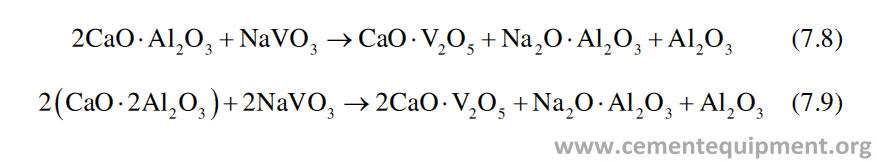
Basic Refractories
Basic refractories are chemically more compatible with the cement chemistry and found to perform very well, especially in kilns with higher thermal load. Magnesia refractories are very prone to crack by thermal shock, and that is why the basic refractories are made always combined with different spinels, as an elastifier, e.g., chrome ore, mag-alumina spinel (MgO·Al2O3), hercynite (FeO·Al2O3), galaxite (MnO·Al2O3), etc., which lowers down its modulus of elasticity and improves dras-tically its thermal shock resistance. The thermal expansion coefficient of the dead burnt magnesia and the elastifying spinels are quite different. Due to mismatch of the thermal expansion coefficient, microcracks are developed in the brick body dur-ing the high-temperature firing of the bricks, as a part of its manufacturing process. These microcracks in the body act as crack arrestors and do not allow a crack to propagate and improve its thermal shock resistance and its ability to withstand more thermo-mechanical stresses.
Whenever the crack develops in the body due to thermal or mechanical stresses, these microcracks do not allow the generated crack to propagate further and improve the thermo-mechanical property to withstand more stresses and improve the resis-tance to thermal shock of the basic bricks.
Alkali Reaction
The major ingredients of basic refractories react with alkalis to form low-melting liquid phases. These liquids penetrate inside the brick pores and densify the brick hot face. Table 7.8 shows the composition and temperature of melting of the liquid phases.
The eutectic of MgO-K2SO4 is 1067 °C and eutectic temperature of MgO-K2CO3 is 895 °C . Therefore the MgO-based Refractories are not really alkali resistant [26]. Ingredients of basic refractories react with alkalis, and some reac-tions are associated with considerable volume changes (Table 7.9) causing destruction of the refractory [21]. Basic Refractories with addition of hybrid Spinels has been developed to withstand the effect of alkali much better [27, 28].
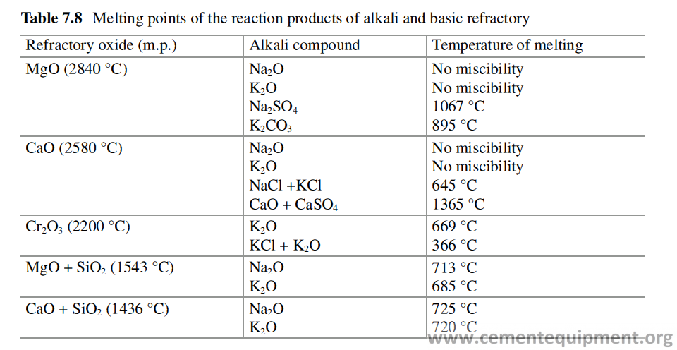
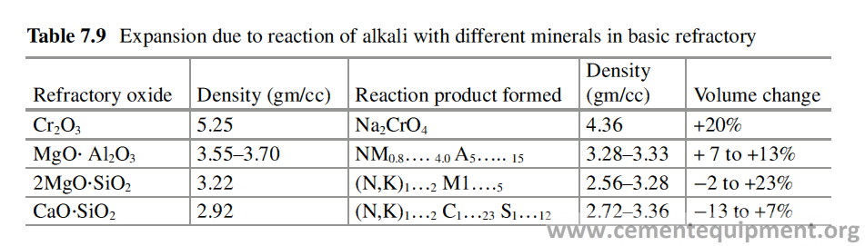
Interaction with SO2 / SO3 /Cl
Free SO2 and SO3 in presence of O2 when exposed to basic Refractories at different temperatures for different time periods, it is found to react with grains and matrix to form CaSO4, MgSO4, and CaMg3(SO4)4 [29]. The brick’s microstructure, before and after reaction, were studied, and Fig. 7.7 shows the SEM photographs of the brick before and after reaction. When both excess SO3 and chlorides are available, the K2O present reacts preferentially with chlorides, and the SO3 reacts with CaO partly available as free lime and Ca-silicates to form CaSO4. That is why the basic bricks with lower content of CaO are an advantage [30].
Magnesia-spinel refractory exhibits excellent performance in most rotary kilns. However, premature wear can occur due to fluctuations in operating conditions. The main wear mechanisms are infiltration by volatile compounds and infiltration by the clinker liquid phase and mechanical stress. In the case of infiltration by the clinker liquid phase, CaO from peritectic decomposition of C3S (C3S → C2S + CaO at 1250 °C) reacts with Al2O3 of the spinel, forming mayenite phase (C12A7) in the temperature range between 1000 °C and 1350 °C, with the probable mechanism indicated in Eq. 7.10 [31].
The mayenite has low refractoriness and deteriorates the refractory property.

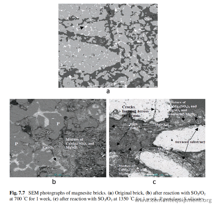
The free SO2/SO3 attacks the CaO-containing silicates of basic refractory bricks in the burning zone. By this, the highly refractory silicate, belite (C2S), decomposes to low-melting silicates, merwinite (C3MS2) and monticellite (CMS), as CaO is released and MgO from the basic Refractory is absorbed. The released CaO reacts with SO3 to form the sulfate salt CaSO4 anhydrite (CaSO4 = + Volume of 27.5%), which densifies the brick structure in deeper brick zones. This type of reaction leads to a corrosion of the brick structure and to lowering of refractoriness as well as structural changes within the affected brick zones. The wear mechanism can be shown by the following equations:
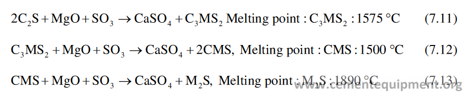
The MgO of the basic bricks are also attacked by the chloride to form MgCl2 to destroy the brick structure.
Hercynite grains (Fig. 7.8) in magnesia-hercynite product, composed of the solid solutions of FeAl2O4 and MAF dispersed in the matrix, underwent dissolution by the cement clinker components [32]. Similarly, magnesioferrite surrounding peri-clase crystals is also found to be dissolved by clinker.
In the image of the after-corrosion magnesia-hercynite product (Fig. 7.9), the solid solution C2 (A, F) can be observed as light gray areas between MgO crystals (dark gray areas) [32]. This intermediate phase is additionally enriched with mag-nesium and silicon oxides. Moreover, crystals of alite, C3S, can be found, which are enriched with the admixtures such as MgO and Al2O3, that constitute components able to stabilize β- and α’-C2S. In the larger distance from the contact zone of the MH product, the areas between the isometric crystals of MgO are filled up by aluminate- ferrite phase of C4AF type that was enriched with SiO2. This phase con-tains admixtures of MAF solid solution with small amounts of SiO2 and CaO as well as the crystals of belite, C2S, stabilized by Fe2O3, Al2O3, and Na2O.
Effect of Vanadium Oxides
The presence of V2O5 increases the amount of the liquid phase, in the pseudo- ternary system CaO-MgO-SiO2, which becomes glass upon quenching. Dicalcium silicate and C3MS2 will be converted by V2O5 to liquids at 1450 °C [25]. The liquid phase between grains will lead to grain growth, reduction in hot strength, and consequent failure of the refractory. For magnesite bricks containing forsterite with low lime content, the forsterite will act as a stable second phase that will limit the liquid pen-etration and the grain growth and will promote bonding of the grains. The corrosion, when both V2O5 and Na2O present together, will be more prominent in basic bricks. Sodium vanadate may react with the dicalcium silicate (2CaO·SiO2), monticellite (CaO·MgO·SiO2), and 2CaO·Al2O3·SiO2 according to the reactions:
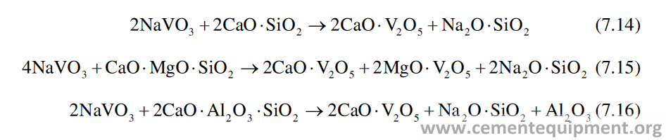
Hydration
The storage of basic refractories is very important. Basic bricks are prone to hydra-tion. MgO in basic refractories reacts with moisture in atmosphere to form magne-sium hydroxide according to reaction 7.19.
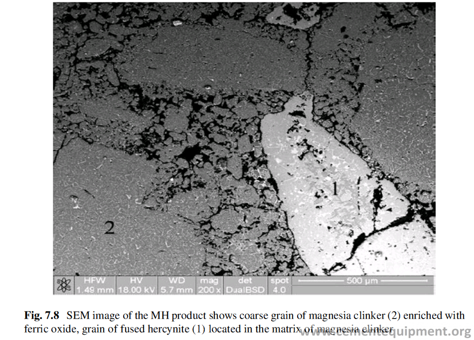
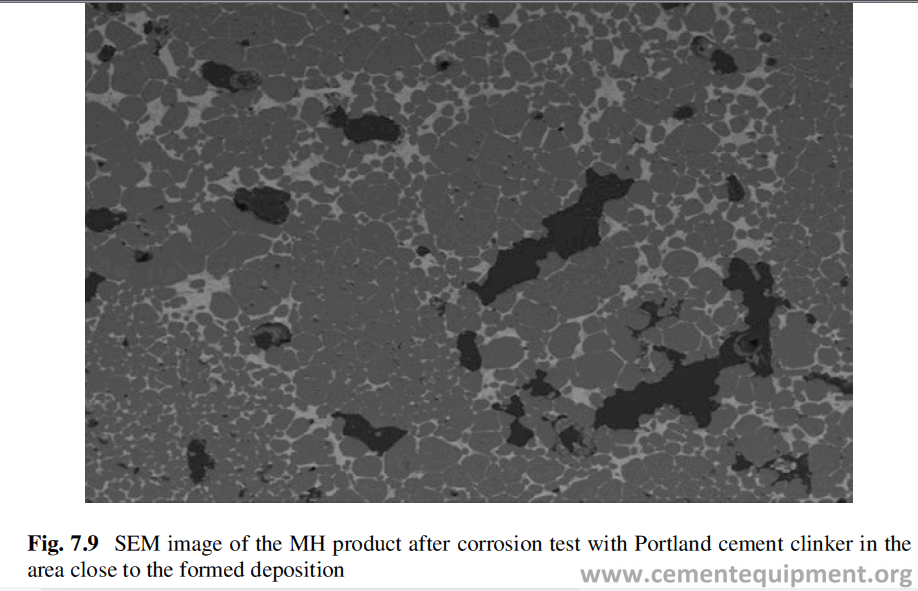

This reaction is associated with volume increase, which results in crack forma-tion in the brick as shown in Fig. 7.10.
The hydration reaction of basic bricks is influenced by the following factors [33–35]:
- Temperature of storage – The higher is the temperature, the higher is the speed of the hydration reaction. It has been seen that even rise of 10 °C in the ambient temperature increases the hydration reaction speed by 60%. Therefore storage should be done at a place where temperature remains low. Impact of temperature on the rate of hydration [34] is shown in Fig. 7.11.
- State of occurrence of water – The hydration reaction proceeds faster, when the water, as reactant, remains in vapor phase rather than in the liquid phase. It means the atmosphere with high humidity is not good for storage of basic bricks.
- The nature of the base raw material of the magnesite refractory – The higher is the processing temperature of the periclase, used in the brick, the higher will be its hydration resistance.
- The composition of the impurity phases – In the basic bricks, besides periclase, other impurities are present, like forsterite (Mg2SiO4), merwinite (Ca3MgSi2O8), dicalcium silicate (CaO·2SiO2), etc. It has been found that when the matrix or the periclase grains contain dicalcium silicate or tricalcium silicate as impurity, the rate of hydration is much faster.
The basic bricks, if found, have a whitish coating on the surface; it indicates the hydrated layer on the surface. To check the penetration of hydrated layer, the brick should be broken to see if there is whitish coating inside also. If there is any indica-tion of hydration found, the bricks should be checked for its suitability for use by the method described below.
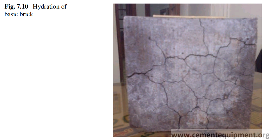
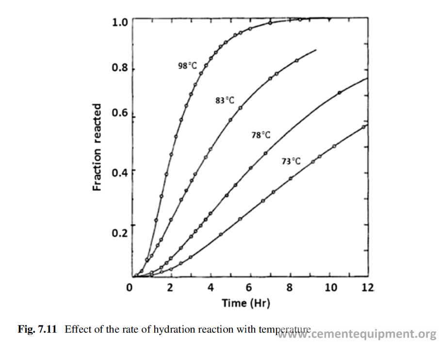
A portion of the brick having weight of about 2–3 kg is taken and dried at 110 °C for 4 hours. The weight is noted. The brick sample is then heated at 1050 °C for 12 hours. The brick sample is cooled and weighed. The difference between the two weights is the indication of hydration. If the weight loss is below 0.2%, the brick is in good condition. If the weight loss is up to 0.6%, it can be used, but the preheating should be done immediately after the installation, and during preheating, it must be maintained at 1200 °C for 24 hours. The bricks having weight loss more than 0.6% should not be used [36].
Redox Reactions
At a given temperature and standard pressure (ambient, 1 atm), the stability of a pure metal and oxide depends on the partial pressure of oxygen or CO2/CO ratio in the atmosphere. The main reaction involved is

Reducing and oxidizing or redox operating conditions are mostly linked to a not optimum combustion of the utilized secondary fuels. These conditions are mainly locally limited to kiln sections where coarse fuel material is burning directly on the lining. As a consequence, local overheating of bricks occurs, and depending on the oxygen, partial pressure elemental carbon condensation in deeper horizons of the lining may take place. Fundamental signs of thermal overload are wavy, concave surfaces or surfaces, which appear to have melted and solidified. Significant low oxygen partial pressure activates the Boudouard reaction:

Due to presence of CO in a reducing atmosphere on the hot side, elemental car-bon may deposit in lower horizons of the lining in a temperature range below 600 °C. Carbon deposits in form of soot on the internal shell are also observed. Damage to the brickwork by extensive spalling may occur with this so-called car-bon disintegration.
In practice, the stability of a metal or oxide is studied by considering three chem-ical reactions of oxidation: metal into metal oxide, carbon into carbon monoxide, and carbon monoxide to carbon dioxide. The oxygen partial pressure and CO2/CO ratio (at equilibrium) can then be determined by using thermodynamic calculations. As with any chemical reaction, prediction based on purely thermodynamic ground, the oxide with the more negative ΔG will be formed, and the one with less ΔG will be reduced. The Fe2O3, Mn2O3, or Cr2O3 in different types of Refractories can be reduced by CO2/CO gas mixture, and for each oxide there are specific temperature and ratio of CO2 and CO in the mixture when the reduction reaction takes place. Magnesioferrite (MgFe3+2O4), contained in the magnesia brick, is reduced to mag-nesiowustite ((Mg, Fe2+) O), and this involves a significant reduction of volume (>20%). If redox burning cycles get repeated, there are frequent changes between magnesioferrite and magnesiowustite, resulting in the structural weakening of the affected brick lining. This can lead to a premature wear as a result of spallings of the redox-subjected brick lining.
If infiltrated sulfate salts are present in the structures of the refractory lining, and particularly under the influence of sulfur, sulfide compounds can be formed from these, under strongly reducing conditions. Potassium sulfide (K2S), oldhamite (CaS), K2S3, and KFeS2 are found in analysis of used brick samples. When oxidiz-ing conditions predominate again, an oxidation of the sulfides takes place, accom-panied by a significant volume increase. This leads to expansion of the brick structure, resulting in the destruction of the brick.
Some of the reactions, occurring in burning zone, in reducing condition are as follows [37]:
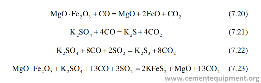
Under oxidizing condition some of the reactions occurring are as follows:
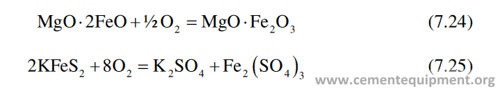
The basic bricks are also affected by the alternate oxidizing reducing environ-ment of the kiln. Bricks, containing high Fe2O3, are particularly affected, because of transformation of Fe2+ to Fe3+ and vice versa. For example, magnesioferrite (MgFe2O4) under reducing condition gets converted to MgO·FeO, which under oxi-dizing condition reverts back to MgFe2O4 as per the reaction given below:
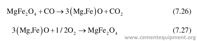
The repeated redox burning cycle causes frequent changes between magnesio-wustite (MgO·FeO) and magnesioferrite (MgO·Fe2O3), resulting in weakening of the brick structure and destruction of the lining Dolomite bricks are found to be very stable under redox condition up to 1800 °C [38].
Attack of the liquid phase
The presence of the liquid phase in clinker is a very important parameter related to cement manufacturing. The liquid phase plays a very important role in nodulization and mineral phase development to determine the cement properties. The four major compounds taking part in cement production are CaO-SiO2- Al2O3-Fe2O3 (C-S-A-F). The eutectic temperature of this system is at 1338 °C. The composition of the liquid formed at this temperature is C, 55%; S, 6%; A, 23%; and F, 16%. The liquid with this composition is unsaturated in respect to SiO2 and can take more SiO2 in solution. Therefore when such liquid comes in contact with aluminosilicate refrac-tory, it takes SiO2 from the refractory and corrodes it. The cement raw mix contains the impurities like MgO, Na2O, K2O, and SO3. Presence of any or all of these impu-rities acts as flux and can bring down the eutectic to 1280 °C. Both the quantity and the rheological property, of the liquid, are very important to cement manufacturing. For most commercial clinkers, the amount of liquid phase present in the clinker is 23–30%. The higher percentage of liquid can damage the refractories badly in absence of a stable coating. As the bricks are infiltrated and saturated with the liq-uid, its modulus of elasticity increases, densification at working face happens, and the refractory may spall.
Liquid phase calculations can be used to predict where in the kiln the stable coat-ing will form. The volume of liquid phase is calculated and plotted day-wise both for 1338 °C and 1450 °C, and the closer the two lines are to each other, the longer will be the stable coating zone [16].
Property of the liquid phase – Temperature has got a very pronounced effect on the viscosity of the liquid. It has been found that increase of temperature in burning zone by 93 °C will reduce the liquid viscosity by 70% [16]. Lower viscosity of the liquid will infiltrate faster into the refractory leading to premature failure of the refractory. MgO, alkali sulfates, fluorides, and chlorides also reduce liquid phase viscosity. For instance, a regular clinker at 1450 °C has a viscosity of 0.16 N.s/m2. Adding 2% SO3 to the clinker reduces that viscosity to 0.05 N·s/m2.
The surface tension of the liquid phase is also an important parameter. High sur-face tension of the liquid helps in better nodulization, but it will have lesser ten-dency to wet the refractory surface, and it may hamper the coating formation. Alkali, MgO, and SO3 reduce the surface tension of the liquid phase in the clinker, and they are good coating promoters. Therefore only the upgradation in refractory quality will not give desired performance of refractory lining, unless we look into the things in totality.
Thermal Load
Beside the normal factors affecting thermal load, the operation of the burner and the protective coating formation are very important to influence the refractory perfor-mance. Misaligned burner or badly controlled power output of the burner can cause critical temperature peaks in parts of the lining, leading to mismatched thermal expansion. The coating is a very effective insulation and protection for the lining. In the production of cement clinker, the coating formation is vital for manufacturing the clinker economically.
It is found by experience that up to a thermal load of 13 GJ/m2h, high alumina bricks are working satisfactorily, when other operational parameters are within tol-erable limit. Beyond this value of thermal loading, basic refractories, e.g., magnesia- spinel, work much better, and if the thermal loading exceeds 21 GJ/m2h, special care must be taken in selecting the refractory. In such case very pure grade of magnesia- alumina or magnesia-zirconia lining should be used.
Overheating
Overheating is one of the important factors which cause severe damage of Refractory lining in rotary kiln. The overheated refractory lining can be recognized by its look as if it is washed out in plane or concave pattern.
The ability of a refractory to withstand certain temperature is judged by its refractoriness or PCE value (refer to Sect. 1.3.6.1). Although this test gives the idea of its softening behavior, this test does not simulate the actual operating condition to which the refractory is exposed during operation. The laboratory test sample is generally pure and not infiltrated, there is no mechanical stress, and the heat up is slow. The risk factor of a refractory lining to get damaged through overheating in a rotary kiln can be assessed by risk factor which is defined as.
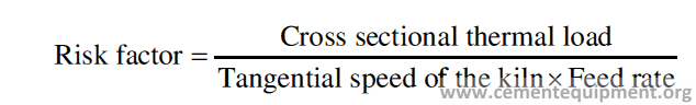
The risk increases with higher thermal load, decreasing kiln speed and decreas-ing feed rate. It is easy to control the fuel burning rate and tangential speed of the kiln, but it is beyond the control of the kiln operator that how the feed material will flow along the length of the kiln. Ring formation, variations in fuel chemistry, excessive coating, massive coating losses, variation in fuel properties, variation in kiln feed properties, kiln slowdown, and burner pipe deformation are just a few fac-tors that can cause fast and localized brick overheating. The best tool to prevent brick overheating is the NOx analyzer, because of its fast response. For a given fuel chemistry, the burning zone temperature is a linear function of NOx concentration. Shell temperature scanners are also powerful tools provided the alarms are set on trends, not maximum shell temperature.
Flame
In rotary kiln, the heat exchange between the burner and the material in the burning zone takes place by three principal mechanisms: radiation, conduction, and convec-tion. The objective is to maximize the transfer of heat generated by the flame to the incoming material in the burning zone. The most important mechanism of heat transfer from flame to the clinker is radiation, and in the burning zone, about 95% of the heat transfer is through radiation. Radiation between two materials takes place when the materials are not in contact with each other. The flame, refractory, and coating radiate heat to the feed in the kiln.
The mathematical expression for heat transfer by radiation is
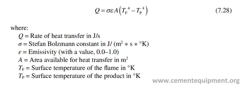
The heat is transferred from the flame to the bed of material mainly by radiation. Heat transfer in the burning zone is a very quick process because the gas velocity is high. In the formula for radiation, the heat transferred is proportional to the fourth power of the temperature of the flame. Therefore the flame temperature has got a very strong influence on the heat transferred. For example, a temperature increase by 10% gives a radiation, increased by (1.1)4 = 1.464, i.e., 46%. This gives a clear idea about the strong influence of temperature increase on radiation [39].
Flame temperature can be approximated by the mathematical formula [40]
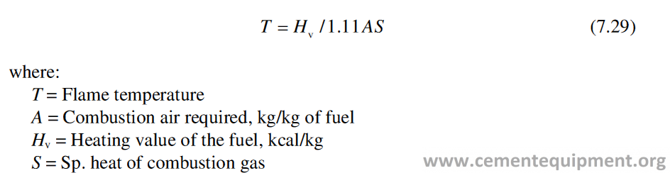
The mathematical relation shows that the radiation depends upon the emissivity of the flame which is different for different fuel. The emissivity of the flame from gas, oil, and coal is as given in Table 7.10 [39].
The burner design and the flame quality have got profound effect on the perfor-mance of refractory, besides the quality of cement clinker produced. The effect is more prominent in case of larger diameter kilns using multichannel burners. For better and uniform burning, the desired flame must be hot and convergent.
When the flame is short and divergent, it cuts the refractory lining like the knife cuts butter. An index, called swirl number, can be used to measure the damaging effect of the flame. If the swirl number exceed 0.8, there is a chance that even the best quality of refractory lining will get damaged. The flame impingement occurs because of high quantity of swirled air, high velocity of the flame, and the distorted burner tip. The ideal flame must be stable and short. When the primary air quantity, speed, and swirl increase, the flame becomes short. Increase in temperature of secondary air, increase in fineness of solid fuel, and lowering of ash content and its volatile matter make the flame short.
Impingement of partially burned fuel upon the feed bed or kiln wall must always be avoided when a kiln is fired by coal or oil. The impingement of the flame, on the kiln wall, causes damages to refractory lining, reduces the fuel efficiency, and affects the kiln stability.
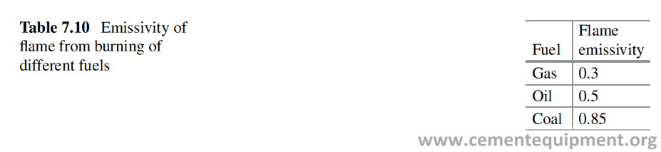
Thermo- mechanical Aspect
Kiln shells are made with structural rolled steel plate, such as ASTM, A 36. The properties for this type of steel are:
Carbon – 0.25%
Manganese – 0.80–1.20%
Phosphorus – 0.04%
max Sulfur – 0.05%
max Silicon – 0.40%
The mechanical properties of this type of steel at room temperature are:
Tensile strength – 345–550 MPa
Yield strength – 250 MPa Min
Elongation – 20% Min
Linear thermal expansion coefficient – 11.7 × 10⁻⁶/°C Elastic modulus – 207 GPa
Poisson ratio – 0.3 in the elastic range, 0.5 in the plastic range
Steel loses its mechanical strength at elevated temperature. At 430 °C, the ulti-mate strength of the steel drops from 517 MPa to 345 MPa, with a hefty 33% loss. Some investigators report a 50% strength loss for the same temperature range. Thermo- mechanical stress generated in the kiln, during the operation of the kiln, is because of various factors, e.g., the ovality of the kiln shell, the restricted expansion of the refractory, etc. Thermal expansions of the Refractory lining, the rotary kiln shell, and the tire are fundamental issues related to the stress development. The developed thermo-mechanical stresses have got direct effect on the refractory per-formances, and it appears in different forms like falling of bricks from the ring, crushing and slabbing of refractories, etc [41]. The gap between the tire and the chair pads has to be sufficient for the thermal expansion of the steel shell. Too tight riding tire can inhibit thermal expansion of the steel shell, leading to the failure of the lining or even the tire. On the other hand, the gap cannot be too large as it affects ovality negatively.
Ovality
The shell of the kiln is made of mild steel plate as given in Sect. 7.6. Steel is the only viable material for the purpose but presents the problem that the maximum tempera-ture of the feed inside the kiln is over 1400 °C, while the gas temperatures reach 1900 °C. The melting point of mild steel is around 1300 °C, and it starts to weaken at 480 °C, so considerable effort is required to protect the shell from overheating.
Brick lining is tightly fitted to the steel casing of the kiln. During the usage of the kiln (starts, stops, and rotation), the steel casing and therefore the lining are subjected to radial and longitudinal bending, vibrations, and torsion. Additional stresses can typically arise from misalignment of the kiln or other abnormalities. This results into different stress-controlled loads in the lining. Here, stress-controlled loads define external loads such as gravity load, pressure load, or any type of mechanical load. Different kinds of deformation of the kiln are caused by the dif-ferent loads mentioned and can be identified by regular inspection of the kiln [42]. Radial bending of the kiln, known as the ovality of the kiln, traditionally belongs to one of the most important load generators in the refractory lining and directly affects its campaign life. Ovality is an elastic distortion of the kiln shell that arises due to the gravity force. The weight of the casing, the lining, and the coating over kiln’s hollow shape makes the shell somewhat oval rather than circular (Fig. 7.12).
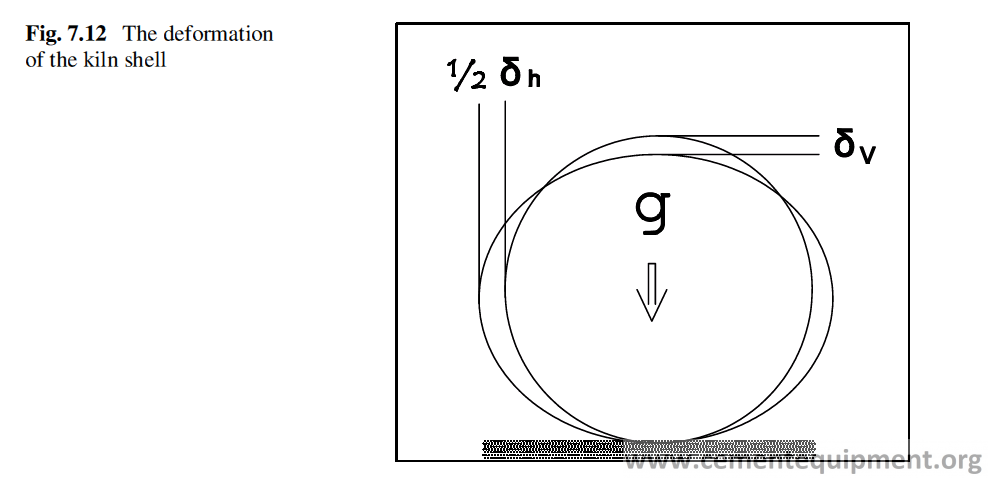
The difference (δv and δh) between deviations of vertical and horizontal diameter of the kiln from the actual shell diameter generally amounts to 0.3%, and for an old and large diameter kiln, it can go up to 0.6–0.7%.
Due to the ovality of the steel shell, the lining will experience load oscillations during rotation of the kiln. This may lead to the formation of cracks and eventually to the slabbing of the refractory lining (Figs. 7.15 and 7.18).
Additionally, bricks in the lining are forced to shift their relative position to each other due to the ovality. By that, opening up of the joints leads to worsen the integ-rity of the brick lining and may cause unhealthy stress concentrations.
Ovality is commonly presented in percent, as relative deformation to the nominal diameter. If the deformation is known, then relative ovality (ωr) is found by equation
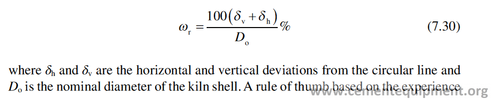
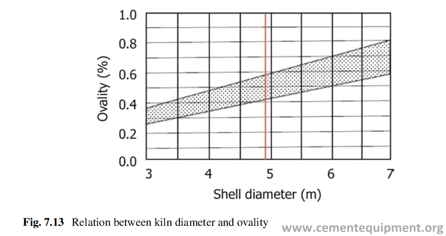
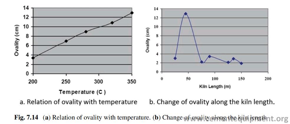
has been established, suggesting that the ovality of the steel casing should not exceed 10% of the nominal inner diameter. For example, a kiln with a nominal inner diameter of 6 m should not have relative ovality of more than 0.6%. The ovality of the kiln shell increases with diameter of the kiln (Fig. 7.13).
The magnitude of ovality is mainly dependent on the thickness of the steel shell, the gap between the tire and the pads, and the operating temperature (Fig. 7.14a) [43]. The relation between the ovality along the kiln length is shown in Fig. 7.14b. The increase of ovality in the tire region is clear from the figure. The ovality is sig-nificantly higher on the tire close to burning zone. The chances of ovality will be more in old kilns in which the shell thickness gets reduced due to corrosion over long time period.
The ovality is highest near the tires, and statistically most of the repair jobs of the lining are done close to the downhill tire. Additionally, the ovality of kiln does not remain permanent but changes with operating conditions. When the lining is newly installed, the ovality tends to be at its lowest point and increases after some time. Wear of chair pads gradually increases ovality. If the lining is covered with clinker coating, the effect of temperature is lowered, and therefore the ovality is lowered as well.
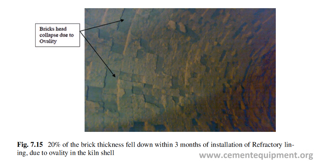
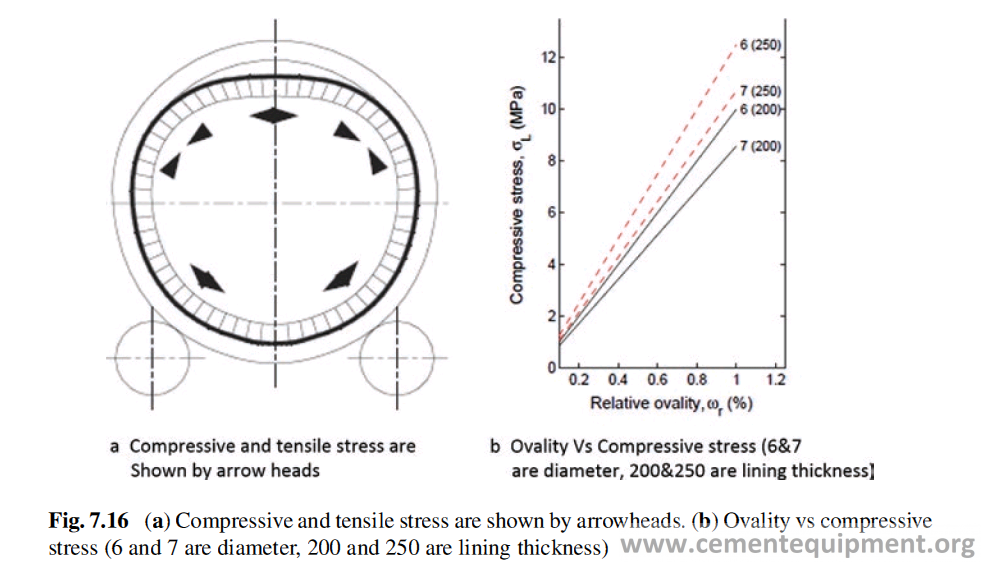
The understandable fact is that cross section of a rotary kiln shell is not perfectly circular but flattened due to gravity force. The influence of gravity is schematically represented in Fig. 7.12. The under-tire shell’s sections are the places, where it occurs. In these places the elastic shell, mounted with the tire ring, changes (self- adjust) its shape to quasi-circular inside diameter of ring (Fig. 7.16a). It happens under the influence of shell’s self-weight and the weight of the internal lining.
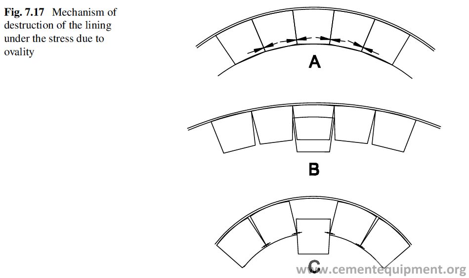
The compression and relaxation in the lining are shown by arrowheads in Fig. 7.16a.
Magnitude of compressive stresses in the lining, induced by the ovality of the kiln, can be expressed by the following equation [44]:
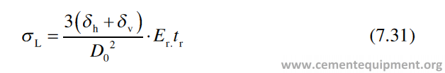
Here, σL = compressive stress induced on the inner wall of the lining due to ovality of kiln shell, Er = Young’s modulus of the Refractory used for the lining, and tr = the thickness of the refractory lining. According to this expression, the stress increases with increased ovality, Young’s modulus, and lining thickness. The compressive stress increases sharply with increasing ovality and with increased lining thickness (Fig. 7.16b).
A kiln having three rotations per minute will produce 13,000 cycles of alternat-ing compression and relaxation per day per brick. Such alternating forces can lead to the brick falling out or chipping out and can have a fatigue effect. Typical mecha-nisms of lining degradation are shown in Fig. 7.17. A perfect lining situation, that is, when the shell is not deformed and bricks correctly adjoin each other, is shown in Fig. 7.17a. The distribution of forces in the contact areas between the bricks is shown. Figure 7.17b shows a situation, when, during rotation of the kiln, the radius of curvature increases excessively, the load on the surface of the bricks decreases, and even the gaps between them become wider. When the shell radius becomes large enough, the bricks may move downwards or even fall out totally.
When a brick falls out, the adjacent bricks become loose, so subsequently it might lead to falling of other bricks, thus exposing the steel shell to high tempera-tures. If a loosened brick does not fall out but stays in place (Fig. 7.17b), then dur-ing rotation of the kiln at the same circumferential position of the shell with a reduced radius of curvature, the bricks will experience a compressive stress (Fig. 7.17c) [45].
Such a situation might cause the breaking of the downwardly moved brick, in the cross section, compressed by the edges of adjacent bricks and the chipping out of a large portion of this brick. The remaining part will resume its original posi-tion, but the lining in this area already becomes significantly thinner. In case of smaller radius changes or better fit of the bricks (smaller initial play at installa-tion), the movement of the brick is limited, but chipping can be observed (Figs. 7.15 and 7.18).
There is a linear relationship between the ovality and the wear-out speed of the lining [43], and the higher the ovality, the more is the speed of wear-out (Fig. 7.19).
Determination of Ovality
This can be estimated by introducing a parameter shell ovality ratio. The definition of this parameter is based on assumption that a deformed cross section of the shell can be sufficiently approximated by an ellipse [45]. Then the degree of flattening (ovality) of an ellipse can be described by the formula, ω = 2(a-b), where 2a and 2b are the major and minor axis of the ellipse (Fig. 7.20).
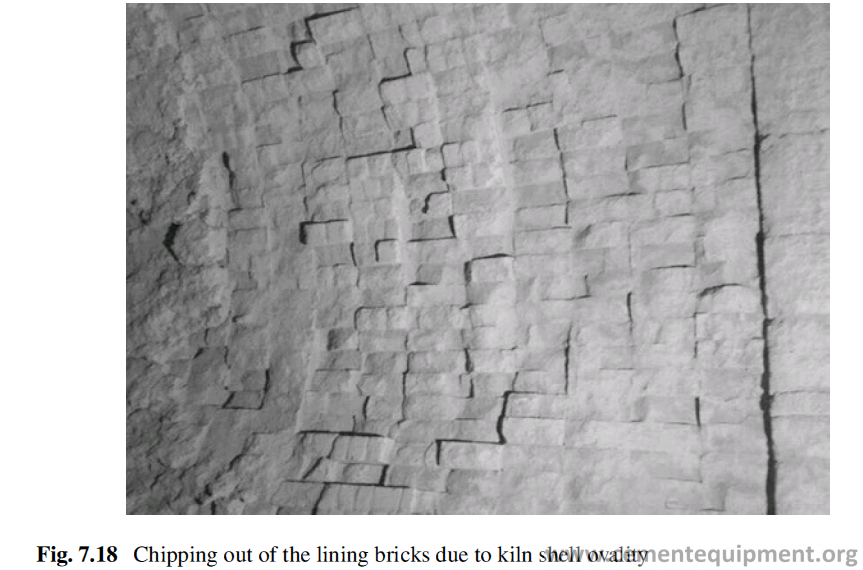
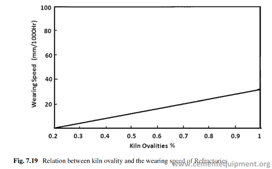
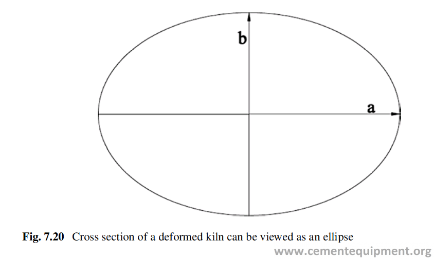
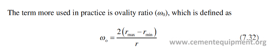
where r is the radius of the kiln without any flattening and rmax and rmin are the maxi-mum and minimum radii during flattening of the shell. In actual practice, it is very difficult to measure the ovality using this equation. For practical determination of ovality, a shelltester device (Fig. 7.21) is used, which works on the principle based on Rosenblad formula below, with reference to the diagram, shown in Fig. 7.22:
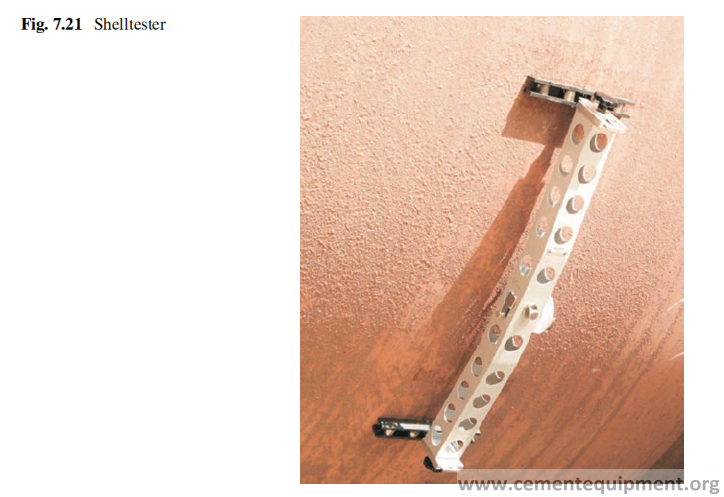
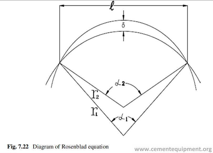
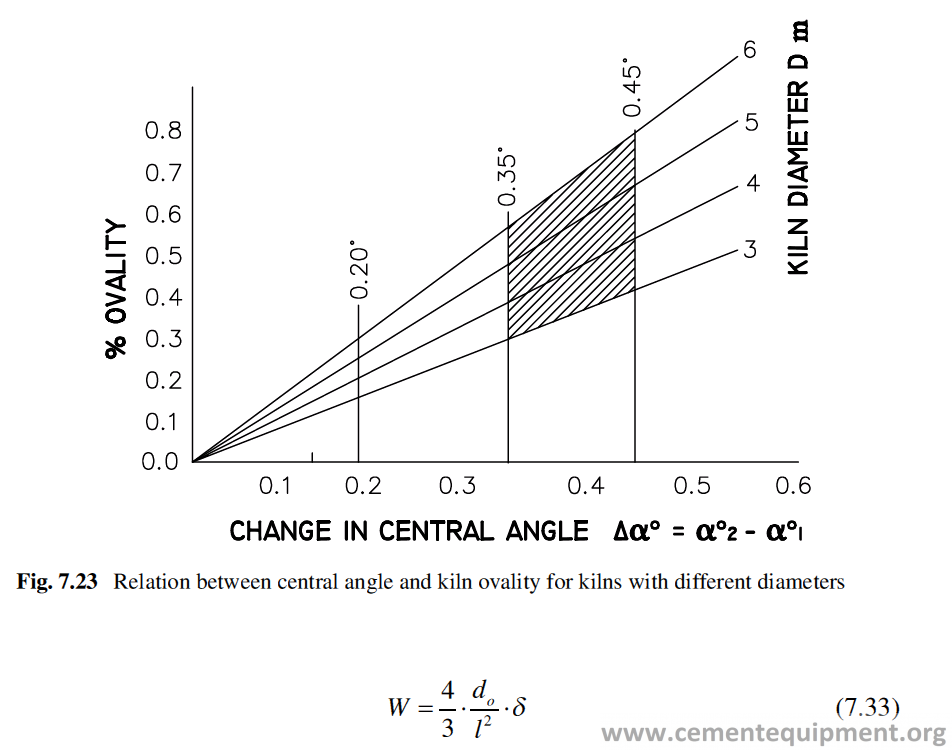
The value of l is the length of the shelltester (Fig. 7.21) and do is the diameter of undistorted shell. The δ (deformation) value can be measured with the shelltester, and the kiln ovality at any point on the kiln can be measured using Rosenblad formula (7.33). The variation of the ovality depends upon the kiln diameter, and the relation of kiln diameter, kiln ovality, and the central angle is shown in Fig. 7.23.
The maximum allowable amount of shell flexing or ovality which is an empiri-cally derived value based on decades of experience and studies is 1/10 of the inner diameter in percent.
For a kiln of diameter 4 m, with ovality 0.4%, the absolute ovality is 0.4/100 × 4000 = 16 mm, which is the difference between the largest diameter, presumably the horizontal one and the smallest diameter, presumably the vertical one, while the kiln rotates.
During the turn of the kiln, every point connected with the surface of the shell migrates not on the circle but over the distorted outline, whose radius of curvature has different values for every next circumference position of this point. The relative changes of the radius in respect to the function of the angle of the kiln’s rotation are shown in the Fig. 7.24.
The pattern of the graph of shell deflection vs rotation tells about the condition of the kiln with respect to alignment, load distribution on piers, the tire shell gap, etc. as shown in Fig. 7.24. The proper interpretation of the graph (Fig. 7.25) and taking necessary step to rectify the problems can improve the refractory performance.
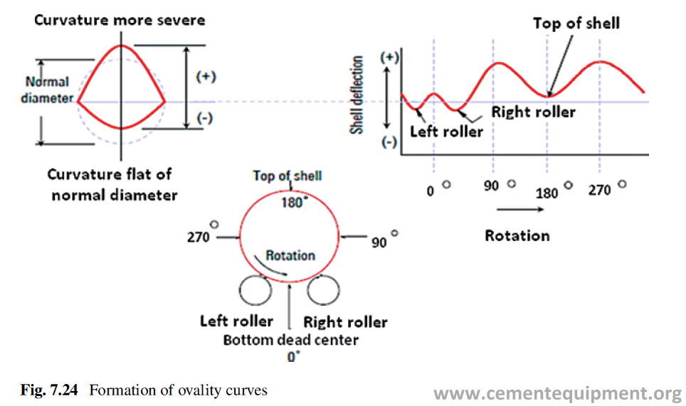
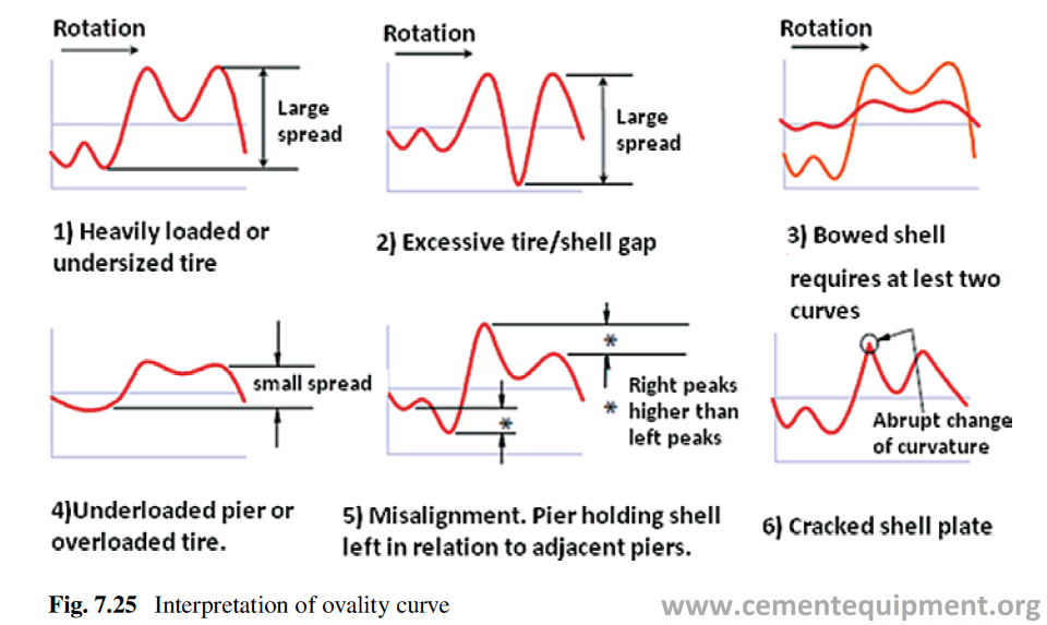
Cranking
Different type of stresses act on the kiln shell which disturbs its axial alignment in vertical or in horizontal plane and this is termed as crank [46, 47]. This alignment must be checked regularly for better refractory life. There are two types of cranks, thermal cranks and permanent or mechanical cranks. A thermal crank is caused by the process, e.g., from uneven coating or refractory thickness inside the kiln, which causes an uneven circumferential temperature distribution in the kiln shell. The areas with different temperatures have different thermal expansions and bend the kiln slightly. A permanent or mechanical crank can originate from an error during assem-bly, overheating (hot spot), or loss of rotation in hot conditions. Both local deforma-tion and the eccentricity have a significant effect on the performance and campaign life of refractories. Those can cause displacement of the brick from its original posi-tion and may cause falling and crushing of the bricks.
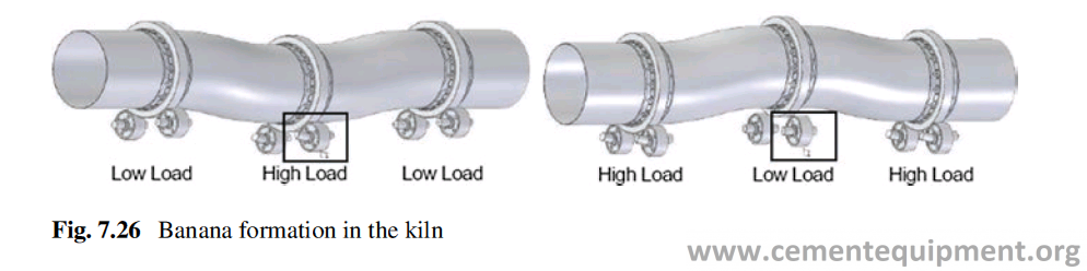
Laser range finders can be used to measure such deformations. The falling of bricks further overheats the shell, causing incremental cranking. The problem is also known as the formation of banana of the kiln. Figure 7.26 shows the cranking of the kiln.
It has been found that kiln crank causes refractory failures happening in between the piers and the refractory failures on tier region are associated with kiln shell oval-ity and tier gap. In the actual production process, the offset of the kiln axis cannot be allowed to exceed 3 mm. Practice proved that the accurate control of the kiln axis at the hot condition reduces the refractory wear.
Creep and Migration of Tires
The riding rings provide substantial strength to the kiln shell by maintaining shell roundness. Because the shell naturally flattens out at the 12 o’clock position, the riding ring system must maintain shell integrity by minimizing flex. Tire is much thicker than the kiln shell, and its average temperature rise is less than that of the shell. Thermal expansion, therefore, increases the diameter of the shell by a greater amount than it does the tire. If this differential expansion is not carefully accom-modated, the tire may restrict shell expansion, distorting it permanently, and the refractory in this area can be crushed, yielding undesirable results. Hence the tire must be loose on the shell. To accommodate any difference in the thermal expansion rate of the shell and the tire, there is a difference in the shell outside diameter and the tire inside diameter, and the tire inside diameter is bigger than the shell outside diameter. As the kiln warms to operating conditions, the shell circumference grows to more closely match the tire. Because of this difference, the tire rotates a little bit slower than shell. This can be observed on each revolution by linear movement between both surfaces (Fig. 7.27). This relative movement is called “tire migration,” or “creep,”
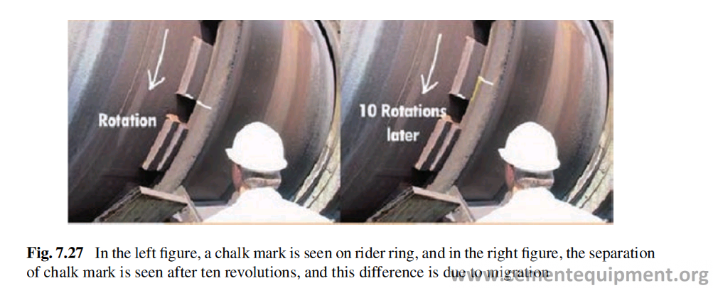
If undeformed tire has inside diameter Do and outside diameter of undeformed kiln shell, above chairs, is do and theoretical clearance between the two perfect cylinders is C, then during each revolution, there is a relative movement U between the tire and the shell, which is equal to the difference of the circumferences and is called as creep and is defined as
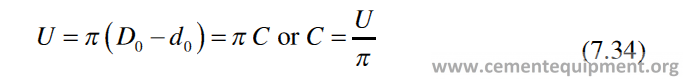
The cyclic changes of the radius of the shell‘s metal plate also have the influence on durability of the kiln’s internal lining.
The creep value can be determined by measuring the separation of the chalk mark (Fig. 7.27) for ten revolutions and then by dividing it by 10 and 3.14. It has been found from the experience that 10–15 mm is the ideal creep per revolution [48].
For smaller diameter kiln (<5 m) and cold stations, it should be 10 mm, and for larger diameter kiln and hot stations, it should be 15 mm. The creep should be mea-sured on daily basis. If the creep is close to 30 mm/rev, then tire shimming is the most wanted solution. A look at the refractory performance history is very impor-tant. Fallen bricks are the sure sign that tire shimming is needed. The cross-check for ovality is also suggested because higher creep value implies a high ovality.
For most kiln producers, tolerance for under-tire clearance is between 3 and 6 mm in hot condition. Under-tire parameter value is directly linked with tempera-ture changes and also with kiln axis position in vertical plane. The sudden tempera-ture change decreases or increases the creep value. It is strongly recommended to keep shell temperature stable around whole kiln circumference. There are many problems given below that can be caused by excessive tire migration:
1-When creep is bigger, wear gets accelerated.
2-Higher ovality of the shell can create problems like refractory lining failure, shell crack and deformation, stopblock welds, or chair pad cracking.
3-Stopblocks or retaining ring wear is faster and can create undercut of tire.
4-Tire axial runout (wobbling).
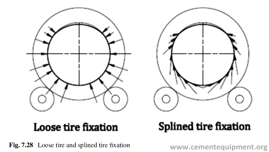
There are two different methods of fixing the rider ring and shell, namely, (1) loose tire fixation and (2) splined tire fixation (Fig. 7.28).
The kiln can be divided into three sections regarding its alignment, and the per-fection of alignment is very important for good refractory life. The three sections mentioned above are:
- The position of the fixed elements such as rollers and the pinion gear
- The position of the tires and the girth gear over these fixed elements
- The position of the shell
Thermal Distribution
Thermal distribution on the kiln shell is very important. If there is coating inside the kiln, it will keep the material inside hot for longer time, and the shell will be hotter than expected. It will lead to increase in the thermal expansion of the shell. If this happens to any pier, the shell will stop migrating at that pier. The expanding shell will force the tire to expand, and the whole load distribution on the roller in that pier will be changed and will ultimately develop stress on refractory lining inside.
Riding rings, with splined tire fixation, provide much better support of the kiln shell. Because the kiln shell is laterally suspended in adequately designed carrying bars, ovality is much reduced, resulting in noticeably better refractory lining life. There is a direct connection between number and type of supports and its ability to distribute the unit load to the shell. The tires guarantee necessary strength to the shell by keeping its roundness. Due to its design, the kiln shell, naturally, flattens at the top position, and the tires must maintain the shell integrity by preventing flex. When the chair pads are worn out, the under-tire gap exceeds the tolerance. This causes bigger shell ovality. Higher value of gap and ovality leads to faster wear of rotating components (chair pads, stopblock, tire side surface, tire outer diameter), and wear is increased with each revolution of the kiln. Beside this the bigger value of creep can lead to crack on the shell segments.
Excessive wear also allows shell to move through the tire which mismatches the tire to the roller and the gear pinion and increases hertz pressure which leads to Refractory spalling at the surface.
In the rotary kiln, thermal expansion up to the skin temperature of 450 °C changes all measurements. If all the rollers are in their correct positions and are keeping the kiln on center line, the deformation and cracks on the shell create eccentric rotations and change the load distribution on the rollers which ultimately affects refractory life.
Strain-Controlled Load
Some part of the expansion of the Refractory lining is compensated by the expan-sion of the steel shell. Additionally, some part of the expansion is compensated by the natural joints between the bricks. However, a part of the expansion is leading to increased stresses, experienced by the lining. The advantage of the expansion is the increased stability of the lining. However, it is important that the expansion is within the technical limitation of the material to withstand the stress. Some additional flex-ibility to a brick lining can be provided by installing the lining with mortar or steel shims between the radial joints. The steel shims and mortar shrink during heating up and create additional expansion space to the lining, by lowering that stresses. However, in cold state, the lining becomes loose than normal after erosion of steel shim or mortar, which might be problematic, if cooling and reheating of the kiln has to be done. The expansion rate of the kiln shell is very important since the Refractory lining is heated faster than the steel shell and the shell is heated faster than the riding tire. The opposite is applicable during cooling. If the heating or cooling is made too fast, kiln shell and the lining risk seizure, due to mismatch in thermal expansion. Typical heating and cooling procedure requires 24–36 h. In addition to the thermal stress due to expansion, the hot face (face of the lining exposed to the flame) of the lining also experiences thermal load oscillations during rotation. This can be due to different factors, e.g., relatively fixed flame direction and gas flow and the cooling effect on the lining when it passes below the bed of material. The thermal oscillation leads to local stresses which risk spalling of the lining.
When the kiln is in operation and reaches an equilibrium regarding the heat flow, a temperature gradient is established across the lining. If the lining is too thin or the lining material has got very high thermal conductivity, the shell may attain a high temperature. The thermal expansion of steel is much more than refractory material. If the thermal expansion of the shell is more than that of refractory, it will exert a tensile stress on the refractory, and the refractory lining may get loosened. On the other hand, if the lining is too thick or the lining material has got low thermal con-ductivity, the steel shell cannot attain a high temperature and cannot expand much,but the refractory lining at high temperature will try to expand, and the lining will experience a high compressive stress.
Thermal Shock
The rotary kiln takes less than a minute to complete one rotation. During this rotation, once the kiln lining comes in contact with the hot kiln gases and the other time it is covered and insulated by the kiln feed. This periodic temperature fluctuation of the lin-ing can go as high as 400 °C and may take its toll on refractory performance, unless the refractory is resistant to thermal shock. The resistance to thermal shock also becomes very important during heating and cooling of the kiln. Faster cooling is more detrimen-tal to the life of refractories specially the basic refractories, than faster heating.
Abrasion of Clinker and Dusts
In the cement kiln system, there is a continuous countercurrent flow of gas and solid material. The flow of high-velocity dust-laden gases and the solid materials in the kiln system has got a very abusive effect on the refractory life, because of the con-tinuous abrasion. Table 7.11 shows the gas velocity in the different application areas in a cement plant.
Inside the kiln, wherever the coatings are formed over the refractory lining, the refractory does not come in direct contact with flow of gas or solid. But at the other places, there can be a very severe abrasion, caused by the flow of solid particles or high-velocity dust-laden gases. The abrasion of TAD lining by the high-velocity dust-laden gases and abrasion of refractory lining by flow of solid material in cal-cining zone of the kiln are shown in Figs. 7.29 and 7.30, respectively.
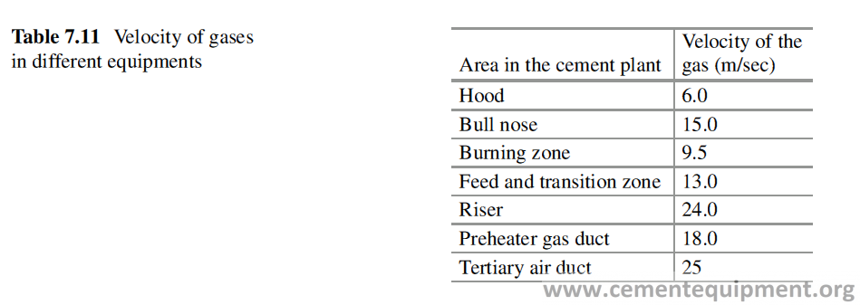
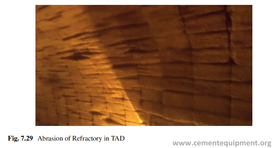
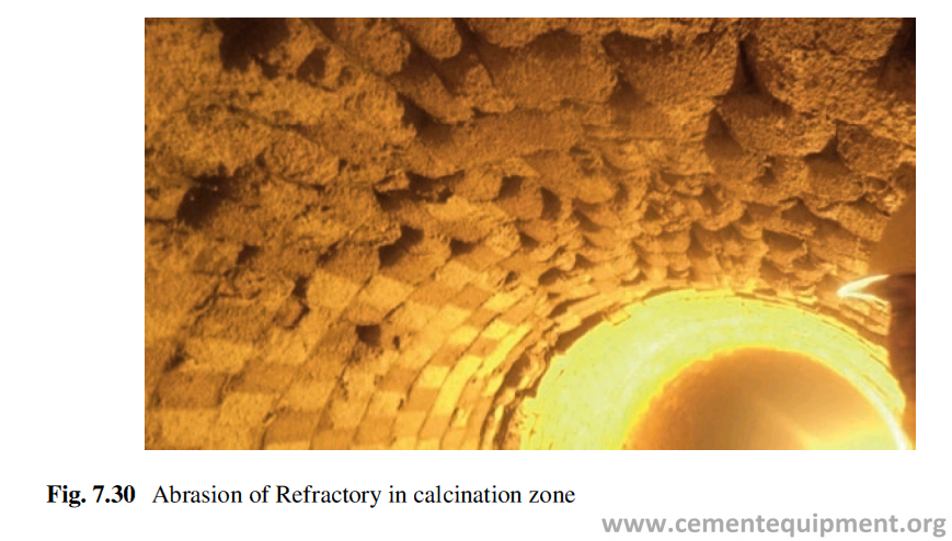
Ring Formation and Buildup
Volatile components such as alkalis, sulfur, and chlorine introduced with raw mate-rials and fuels may give rise to problems in kiln operation when present in high concentrations. Buildup formation in the preheater cyclones or rings in the rotary kiln inlet zone may lead to reduced kiln availability and productivity.Depending on their volatility, alkalis, sulfur, and chlorides evaporate in the sin-tering zone of the rotary kiln and recondense at cooler parts of the system either on the raw meal particles or on the surrounding walls. With the raw meal, they are reintroduced to the sintering zone again, thus establishing a permanent “internal cycle” of volatile “circulating” elements (Fig. 7.31) [49].
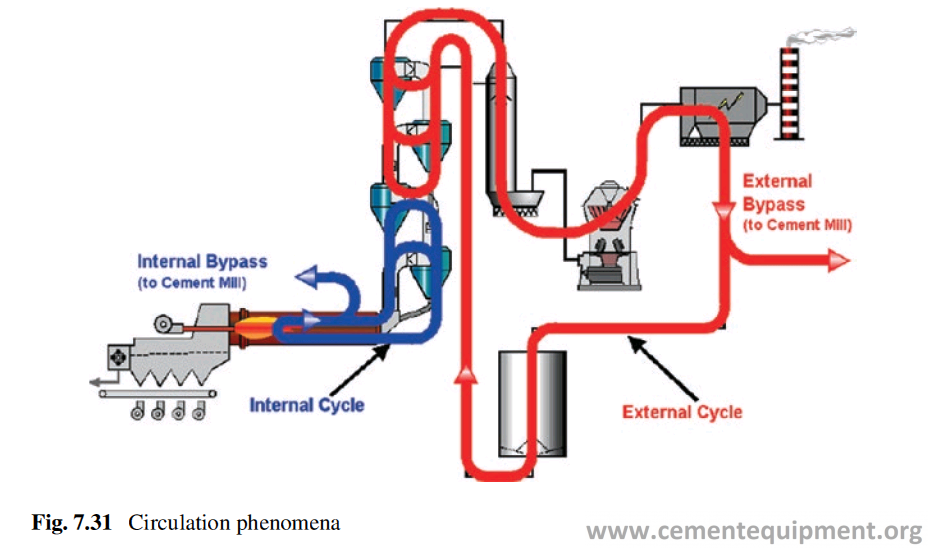
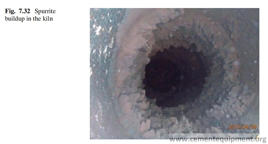
When equilibrium is reached between input and output, a major part of the vola-tile component finally leaves the system and gets incorporated in the clinker.Part of the volatile components, however, may form new compounds such as alkali chlorides or alkali sulfates and other intermediate phases such as spurrite which will then contribute to the buildup phenomena by producing a sticky raw meal adhesive to the walls of the cyclones, the ducts, or the kiln tube.
Buildup inside kiln is a regular problem in many cement plants, specially, where the raw material or fuel contains more sulfur than normal. It is a nightmare to the kiln operator and reduces the production drastically, forcing for a kiln shutdown and removal of the buildup material, which is not a very easy task (Fig. 7.32).
The buildup and ring formation cause the restricted flow of feed in the kiln, the increase in pressure drop of the flue gas inside the kiln with extra power consump-tion in ID fan to maintain the required flow, and the increase of gas velocity in the ring area causing more dusting which enhances further buildup. Removal of the buildup material needs the kiln to cool down and exertion of mechanical force, which causes damage to the refractory lining besides huge production loss [50, 51].
The analysis of the material from the formed ring shows that the mineral respon-sible for ring formation is sulfospurrite. When the molar ratio of sulfur to alkali is more than 1.2, there is considerable amount of excess SO3 remains in circulation in the kiln. This SO3 reacts with the free lime to form CaSO4 which reacts with the K2SO4 to form Ca-langbeinite (K2SO4·2CaSO4). Langbeinite reacts with C2S and forms sulfospurrite (C2S·CaSO4) as per the reaction given below:

Ca-langbeinite and other alkali compounds like K2SO4 form low-temperature eutectic with MgSO4 and CaSO4 which melts at low temperatures (700–800 °C), and these liquid phases, along with sulfospurrite, form the solid ring.
It has been found that some Refractories like SiC (silicon carbide), zircon, etc. can help in reducing the buildup. These refractories on heating form SiO2 which reacts with sulfospurrite, because of its affinity to react with SiO2, and form C2S as per the reaction given below:
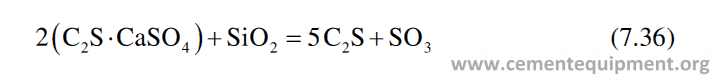
High alumina Refractories impregnated with silica sol were also found to work very good to prevent the ring formation.
With excessive input of volatile elements, the installation of a kiln gas bypass system may become necessary in order to extract part of the circulating elements from the kiln system.
Refractory Failure Due to Anchor
Many a times the Refractory lining fails because of anchor failure. Beside the proper design, the material of the anchor also plays a very important role. It has been found that iron-chromium-based steel anchors are commonly used for high-temperature service conditions. Unfortunately, these alloys are susceptible to embrittlement, when held within or cooled slowly through the temperature range 400–980 °C. There are in fact two significant embrittlement phenomena that occur within this tempera-ture range: the first one is known as 475 °C embrittlement (400–550 °C), and the second one is known as sigma (σ) phase embrittlement (565–980 °C).
The 475 °C embrittlement phenomenon only occurs in ferritic and duplex stain-less steels and not with austenitic stainless steels and can be reversed by heating to 675 °C or above. Therefore 475 °C embrittlement phenomenon is not expected to cause problems for austenitic stainless steel refractory anchor systems.
Sigma Phase Embrittlement
Sigma phase embrittlement occurs because of long exposure of anchors to temperatures in the range 565–850 °C, although this temperature range varies with the composition and processing of the stainless steel. Sigma phase is an iron-chromium intermetallic phase that is extremely hard and brittle [52, 53].
Sigma phase forms more readily in ferritic than in austenitic stainless steels. Elements such as silicon, molybdenum, and to a lesser degree aluminum, tungsten, vanadium, titanium, and niobium all promote σ-phase formation. Large additions of Ni and Mn retard σ-phase formation. Nitrogen, which is now used extensively in the austenitic and duplex stainless steels to stabilize austenite, also helps to retard σ-phase formation. Carbon additions decrease σ-phase formation.
Sigma phase reduces steel’s toughness, creep resistance, and fatigue strength. Although it is not always solely the cause of degradation of properties, therefore each situation must be evaluated to optimize the performance.
In a typical refractory lining, there is always a thermal profile that exists between the hot and cold faces (Fig. 7.33). There are nearly always a portion of the lining and any support anchors, exposed to temperatures within the range of sigma phase formation.
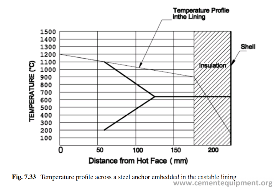
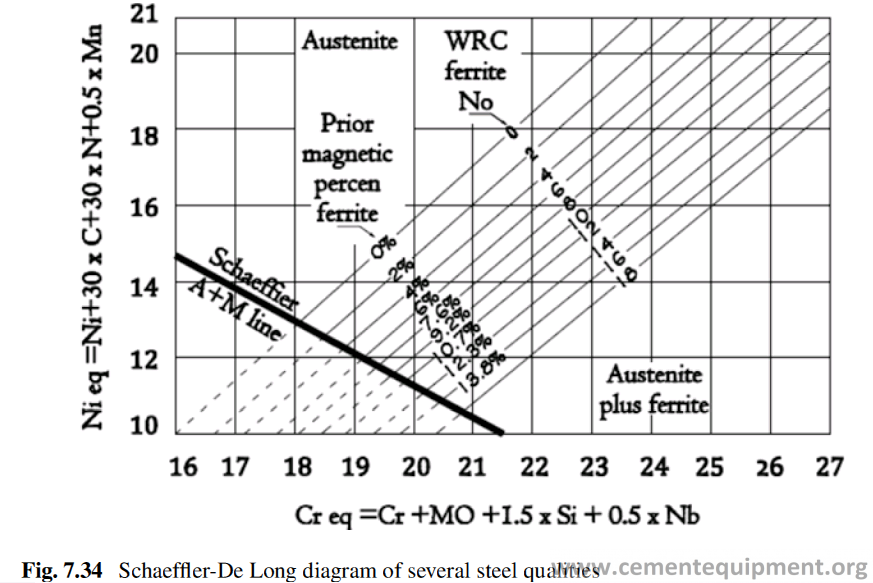
In many common austenitic steels, it is impossible to avoid the formation of this phase entirely. What is possible, however, is to choose a steel or alloy, to minimize the formation of the phase to a level, where the effect does not significantly compro-mise the mechanical properties required by the lining design.
Schaeffler-De Long Diagram
One of the tools available to the design engineer, for that purpose, is the Schaeffler-De Long diagram, which scans the range of alloys and steel by their nickel and chromium equivalents [54, 55]. By plotting these parameters for the common steels/alloys, their susceptibility to σ-phase formation can be assessed to a preliminary degree.
In Fig. 7.34, several common steels have been plotted by these parameters. Resistance to σ-phase formation can be assessed by the “ferrite number” ascribed to the area of the chart in which the steel is plotted. In general, steels occupying the upper left zone of this diagram can be expected to show better resistance to sigma phase formation.
The best selection of the anchor quality for an application is always a compro-mise between the different metal qualities and the operating conditions to minimize the chance of sigma phase formation as shown in Table 7.12.
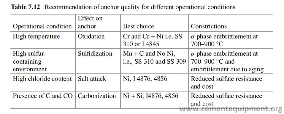
Kiln Diameter
Very common failures in cement plants are falling down of bricks from the rings of rotary kiln, which leads to development of hot spots in the kiln (Fig. 7.35).
This kind of problem occurs mainly with aluminosilicate Refractories and mainly in the calcination zone to kiln entrance end where temperature is comparatively less. The reason of this failure is insufficient tightness of the bricks in the ring.
During the rotation of the kiln, the bricks in the ring, not tightened properly, may come down slowly and fall down. Aluminosilicate refractories, because of the lower thermal expansion coefficient, compared to basic Refractories, are prone to this problem.
High thermal expansion keeps the bricks tight in the lining ring. This phenome-non happens after the upper transition zone to kiln entrance, because no clinker coating forms there, which can hold the bricks together from falling down. After the installation of a brick ring, the insertion of two to three steel shims, in the ring, is very essential. The problem is also more frequent in case of kilns with large diam-eter, because with larger diameter, the key effect of the side arch bricks gets less-ened. The frequent stoppage of the kiln aggravates the problem, because the jerk, in stop and start of the kiln (especially the bigger one), further helps the slippage of the brick from the ring.
Lining Failure Statistics
The studies on the contribution of different factors, e.g., Refractory quality, opera-tional parameters, etc., on the refractory failure in cement rotary kiln were analyzed [56, 57], and the result is shown in Fig. 7.36.
It clearly shows that 77% of the failure or the 3/4 of all the refractory failures in the cement rotary kiln are due to improper operation or improper lining of the refractories. If these two factors are taken well care of, then 3/4 of the all refractory failures can be avoided.
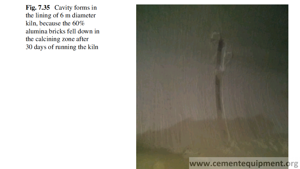
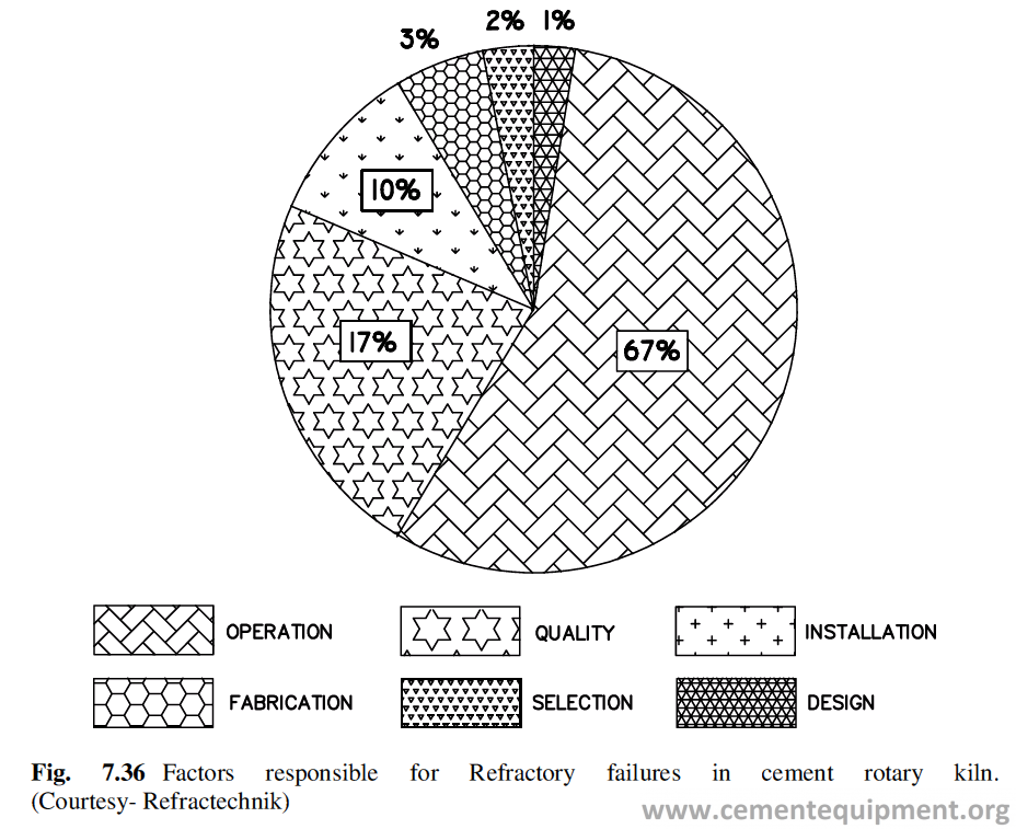
Coating and Burnability of Clinker
Coating and Its Function
Coating over the refractory lining, especially in the burning zone, plays a key role in prolonged operation and reduced energy consumption in cement production. The performance of Refractory lining in burning zone and transition zone of the kiln largely depends upon the soundness of coating on the refractory lining. The burning zone area of the kiln lining, while in operation, is to withstand (1) high temperature, (2) clinker liquid infiltration, (3) flame impingement, (4) thermal cycling, and (5) redox reaction.
The stable coating formation on the refractory lining provides:
1-Protection to the refractory lining from overheating and temperature fluctuations.
2-Protection to chemical attack of the alkali vapors and fuel ash.
3-Protection to abrasion from the moving clinkers and the high-velocity dust-laden gases
4-Protection to kiln shell from the overheating.
5-Improved thermal efficiency and reduction of heat loss from the kiln shell. It hasbeen found that 20 mm thick coating can reduce the heat loss from kiln shell by 50% when the inside bed temperature is 1450 °C [1, 2].
In addition, the unevenness of the coated surface provides proper blending of the feed material and clinker. Experience shows that the importance of coating on refractory surface is more significant in case of large diameter kiln.
The effect of severity of prevailing condition, inside the kiln, can be mitigated by the formation of a stable coating on the refractory surface. Three different condi-tions related to coating formation may arise, namely:
1-Stable coating formation of normal thickness, with minimum stress on the Refractory lining.
2-The coating is unstable with high stress on the refractory lining. Wear of lining takes place discontinuously when the portion of the brick falls down along with the coating material. This happens more in the case of transition zone.
3-Little coating formation, because of low temperature and subsequently continuous wear because of high abrasion and thermal shock. This happens generally in lower transition zone. But no coating formation can also be due to operational trouble of kiln or improper chemistry of the feed material.
Formation
The formation of coating is determined by the quantity and quality of the liquid phase generated during the chemical transformation of raw meal to clinker at high tempera-ture. The quality of the liquid is meant by its characteristics related to viscosity, surface tension, and wettability onto the refractory surface.
There are different oxides present in the feed material, i.e., CaO (C), SiO2(S), Al2O3(A), Fe2O3(F), MgO(M), and K2O(K). Depending upon the presence and proportion of these different constituents in the feed material, each system has an eutectic temperature (Te) at which the melt starts appearing and the tempera-ture of the melt remains constant till all the liquid, which is supposed to be formed at that temperature, forms and then the temperature of the melt rises very slowly (Fig. 8.1).
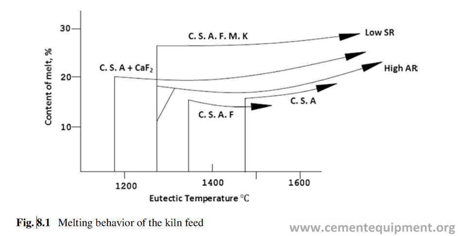
The amount of melt at a given temperature in C-S-A-F system can be derived assuming negligible solid solution of C3S and C2S. For example, as per Lea and Parker formula, the amount of liquid at 1400 °C can be calculated from the for-mula, % Liquid = 2.95% A + 2.2% F. The presence of minor constituents lowers down the Te.
Mechanism of Coating Formation
Refractories in the burning zone play an important role by reacting in a controlled way with the feed material liquid phase, to develop the coating fast, during star-up of the kiln. A suitable refractory should be able to maintain the coating all along under the changing operational condition, and if the coating is lost for any reason, it should be able to build the coating fast. The coating formation on the refractory involved the following steps:
- Chemisorption of the liquid phase in clinker on the refractory surface.
- Infiltration of the liquid in the brick pores to form a continuous film with the liquid on surface.
- Adhesion of the dust and clinker on the refractory surface and buildup of the coating.
- Solidification of the infiltrated liquid in the pores depending on the temperature profile of the brick across the thickness. This forms the mechanical anchoring of the coating.
- The buildup of coating continues till its gravitational pull exceeds the force of adhesion of the coating to the refractory surface.
- The part of destruction of coating due to impact, thermal shock, etc. and rebuild- ing of the coating are a continuous process, while the kiln remains in operation.
It is also common experience to find that the coating on the refractory is notequally strong everywhere, somewhere it is strong and somewhere it is weak.
The most important clinker mineral C3S (alite) requires the presence of liquid for its formation. In the absence of liquid, alite formation is extremely slow and difficult. During alite formation both C2S and CaO dissolve in the liquid, and the Ca ion migrates to C2S by chemical diffusion, and then C3S is formed and crystallized out of the melt. Without the presence of the liquid phase, the diffusion of the Ca ions towards C2S is almost impossible. It is important to mention that Na2O and K2O decrease the mobility of the Ca ion, whereas MgO and sulfates increase the mobility considerably. That is how the addition of gypsum promotes the alite formation. The studies show the relation between the quantity of the liquid phase and the coating formation as shown in Fig. 8.2. Theoretical estimation of coating thickness by mathematical mod-eling from different variables, like the outer shell temperature, coating surface tem-perature, air temperature etc. and it was established that to have an acceptable coating thickness the satisfactory outer shell temperature should be 200–250 [3].
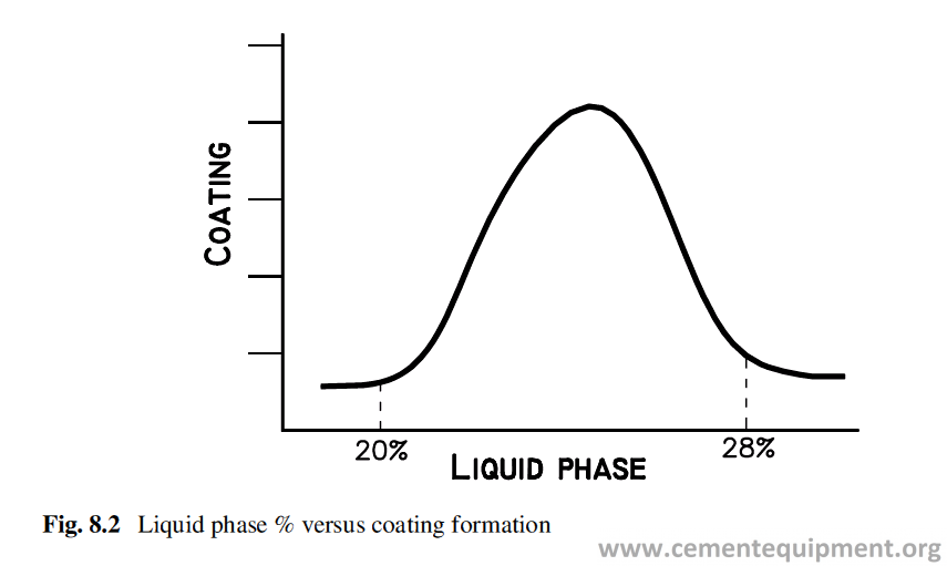
Coating Destabilization and Destruction
The coating becomes unstable and gets destroyed because of the following factors [4, 5]:
- The differential thermal expansion of the refractory and the coating formed.
- The composition of the clinker and coating is almost the same. The coating contains C3S. The C3S is a metastable phase. At a temperature below 1250 °C, C3S transforms into C2S and CaO. This destroys the adherence of coating to the brick surface.
- Change in fuel and drastic change in thermal profile. For example, in a kiln run- ning under steady state, if the fuel is changed from high ash coal to natural gas, the flame will be repositioned, and the coating may drop in certain areas. Moving the burner pipe in or out of the kiln can also destroy the coating.
- Change in the composition of feed. For example, increasing the silica ratio by progressively adding silica to the raw mix will gradually remove the coating.
- Thermal shock due to stoppages and fast cooling of kiln.
- A heavy rain falling on the uncovered kiln will destroy the coating.
Destabilization of coating affects the refractory performance very strongly. A shift from a stable to intermittent coating can increase a brick’s susceptibility to thermal shock, infiltration by alkali sulfates and chlorides, and abrasion by clinker.
Test for Coatability
Although it is a well-established fact that coating protects the refractory in the burning zone and to some extent in the transition zones, any established method has not been devised yet to test the suitability of a refractory for developing coating on its surface.
A good approach to design a test, to determine the coatability of basic Refractory, by the cement clinker, was made by Zongqi Guo [6]. The different test methods were designed, and the methods were tested with statistical tools like design of experiment, ANOVA, etc. to find the response of the test methods towards the dif-ferent factors related to cement manufacturing process and operation. It was found that the sandwich test was quite reliable and rugged and can be applied to compare the bricks for its suitability towards the same feed material.
In this method the refractory under test is cut to prepare the test samples of size 50 × 50 × 50 mm. Two samples together make a set of test sample. Three sets of samples will be used in the test. The raw meal which is to be used for the test is to be calcined at 1000 °C in an alumina crucible in a muffle furnace for 4 hours. It is then cooled to room temperature and pulverized to fine powders, and 50 grams of these pulverized materials are used for three sets of test samples. Fifty gram of the powder is to be mixed with 42 cc of water and mixed well in a mortar. It is an exo-thermic reaction, and the mix will be hot after 3–5 minutes of mixing, the paste is applied on one face of a sample. Before applying the paste, the surface, used for the sandwich test, is brushed with slurry of the mix, made of 33% powder and 67% water. The paste made earlier is spread 4–5 mm thick on the surface brushed with slurry. Then the other sample, of the set, whose one surface is brushed with the slurry, is superimposed on the surface of the first sample, covered with the paste, and pressed to make the paste thickness 2–3 mm.
The sandwich test samples are then put into the electric furnace. A dead weight of 1325 gm is put on the sample (Fig. 8.3), and the temperature is raised at a rate of 4 °C/min to 1550 °C. The furnace temperature is maintained at 1550 °C for half an hour. The furnace is put off and is cooled at a rate of 4 °C/min to room temperature. The modulus of rupture of the fired sample is done as per ASTM standard C133-97 on 90 mm span using three-point bending with a strain rate of 1.0 mm/min.
The significance of different factors on the test methods is established by statisti-cal methods and findings obtained are as follows:
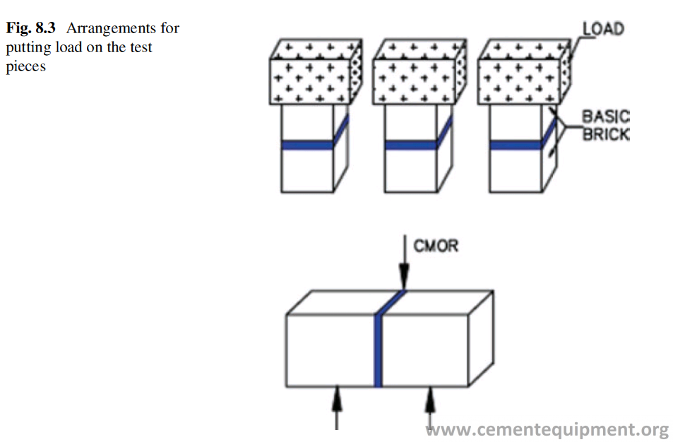
- The compressive load on the samples, the nature of the raw meal, the test tem-perature, and holding time are found to be the most significant factors which determine the adherence strength of the coating.
- Silica ratio of the raw meal is found to have very significant influence on the adherence strength of the coating.
- The effect of heating rate is only significant in the case of magnesia-spinel refractories.
- Particle size has got a very significant effect on the adherence of the coating. The finer is the raw meal, the higher is the adherence.
The ruggedness of the test method to assess the affinity of a refractory towards a feed material was tested statistically, and the results are as follows:
- It is concluded that the sandwich test method is rugged and is insensitive to many minor external factors like the paste thickness, method of making the paste, etc.
- The sandwich test is repeatable and reproducible with small variability.
- The sandwich test is able to differentiate the coating development ability of vari- ous basic The result is found in agreement with the actual perfor- mance of the refractory in the cement rotary kiln.
Effect of Composition and Microstructure
The composition (chemistry) and the microstructure of the Refractory used are also important to decide the quality of the coating. Magnesia-chrome or magnesia- hercynite refractory is found to develop coating much better, compared to magnesia- spinel refractory. The volume of the pores and the pore size distribution are very important parameters to decide the strength of adherence of the coating.
Coating Collapse
Sometimes the large parts of this coating break away from the refractory in big lumps, due to excessive weight, large temperature changes in the burning zone (especially sharp temperature drops), fluctuations of the raw material properties, inadequate operation, and others, and the phenomena is known as coating collapse.
A coating collapse is detected primarily through the kiln amperes. A sharp increase in the average kiln ampere indicates that suddenly a higher amount of material has to be moved in the kiln. Constant spiking of the kiln amps may also indicate an uneven loss of coating in one area of the kiln.
Burnability
Burnability is a measure of the ease of formation of clinker from the raw meal. Coatability of a raw meal is related to its burnability also. With hard burning mate-rial, the coatability is also low. It is actually measured by the free or nonreactive CaO % in the clinker. Burnability depends on the following factors:
- The chemistry of the kiln feed
- Mineralogy of the kiln feed
- The particle size distribution of the kiln feed
Burnability Test
Different attempts have been made to draw a relation between the chemistry of the kiln feed and the burnability and to quantify it.
Burnability of different kiln feed can be compared in the laboratory following a test method.
In this method the sample of the kiln feed is taken and mixed with the coal ash in the same proportion as the coal is used per ton of clinker produced. The mixture of kiln feed and the ash is nodulized and burned at 1500 °C, and then the free lime is checked in it. The lower is the quantity of the free lime, the better is its burnability. The chart of the free lime vs burnability is shown in Table 8.1. The attempt has been made also to map the burnability in respect to silica modulus (X-axis) and alumina ratio (Y-axis), and it has been found that for a kiln feed with silica modulus 2.5 and the alumina ratio 1.6, the burnability property is the best (Fig. 8.4). In some cases the mineralizer is added to improve the burnability of the kiln feed. But it is very important for refractory lining to have a good and stable coating over it, to get a good performance of the refractory lining.
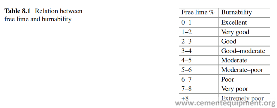
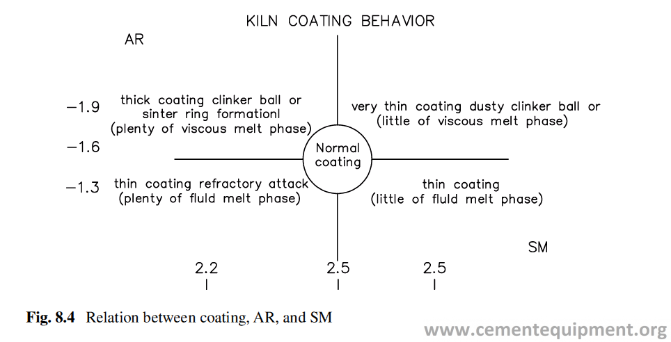
Heat Transfer
Introduction
Cement manufacturing is a very energy-intensive process and requires both thermal and electrical energy. For a modern cement plant, the thermal energy requirement is 3–4 GJ/ton of clinker [1–3]. The calculation shows that about 15% heat is lost in the total manufacturing process through convection and radiation [3]. Heat loss from any equipment surface is proportional to its surface area, and for a modern kiln of 6 m diameter and 70 m length, the surface area is 1320 m2 which is a large value and hence the heat loss is also high. Similarly heat is lost through the surfaces of all other equipments.
The heat energy is kept confined in different equipments to use that energy to carry out the desired chemical and physical processes in cement manufacturing. The Refractory acts as a barrier to restrict the flow of energy from the container (the equipment) to the ambience. The thermal energy flows inside the equipment through combustion of fuel, and at the beginning the process remains in an unsteady state. Part of the energy is utilized to heat up the equipments and accessories, part is con-sumed for different physical and chemical changes taking place in manufacturing process. Part of the energy leaves the system through radiation and convection from equipment surfaces and part through different materials, e.g. flue gas, clinker etc, which leave the system with sensible heat, e.g., clinker, flue gas, dusts, etc. The whole system gradually tends towards attaining a steady state or a state of equilibrium, when the sum of heat input and the heat energy evolved in chemical processes will be equal to the sum of heat energy absorbed in the chemical reaction and the heat lost through the system. To prevent the heat loss from the surface, the surface temperature must have to be low. To keep the surface temperature low, the refractory design must be done very judiciously, within permissible limit of thickness and weight. The insu-lation refractories play a major role to conserve energy from being lost.
Mechanism of Heat Transfer
The heat energy from inside the kiln or any other equipment is transferred by con-duction through refractory wall and gets lost in ambience from surface through the process of convection and radiation. Although the overall heat transfer process cal-culation is quite complex, but for design purpose some basic mathematical equa-tions and expressions can be used.
Conduction
Conduction is the process of heat transfer from a body at higher temperature to a body at lower temperature when there is physical contact between the bodies. Temperature difference between two bodies is the driving force behind the heat transfer process. Conduction occurs on the molecular scale, and the energy of par-ticles having higher energy is transferred to particles with lower energy till they arrive at a state of equilibrium. Conduction of heat through a composite wall is shown in Fig. 9.1; the Fourier equation can be used to determine the heat transfer across the composite wall. If QCond is the heat conducted through the refractory wall of surface area A, comprising of refractory of quality B with thickness D1 and qual-ity C with thickness D2, and if the temperatures at hot face and cold face of the wall are Th and Ts and the thermal conductivities of the refractories B and C are K1 and K2, and the junction temperature is Tj, then the following mathematical expression indicates the relation between temperature drop across the thickness of the refrac-tory lining:
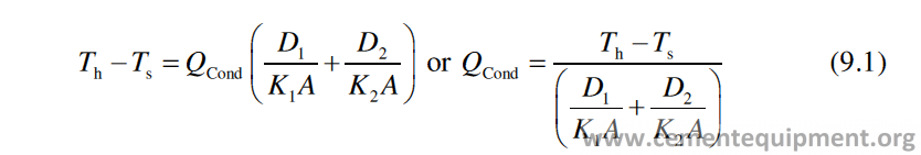
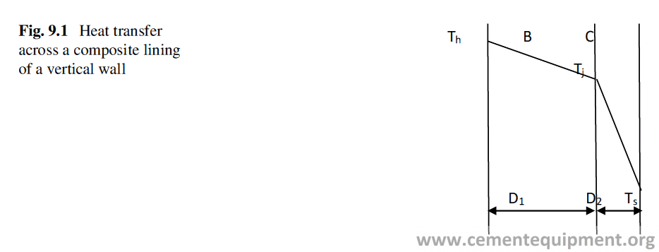
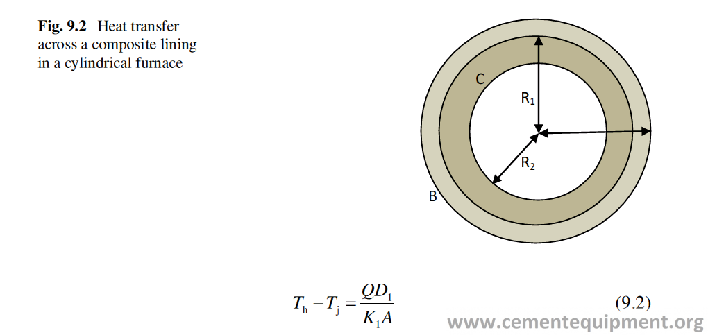
In case of a cylindrical vessel of radius R with inside temperature Th lined inside with refractories B and C, as shown in Fig. 9.2, with thickness D1 = (R–R1) and D2 = (R1–R2), and outside temperature is Ts, then the heat transfer due to conduction over a surface area of A will be expressed as
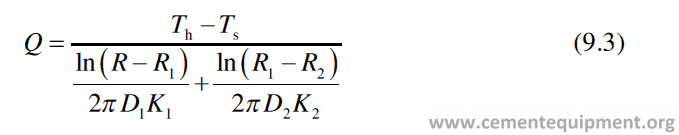
K1 and K2 are the thermal conductivities of the material B and C.
Nowadays the softwares are available to calculate the cold face temperatures. If the software is fed with refractory thickness, density, specific heat, and thermal conductivity values, it can calculate the heat transfer across the wall, junction tem-perature, and the temperature on the outside wall.
The same can be determined manually by trial and error method also. At steady state, the heat flux conducted from hot face to cold face of the lining is equal to the total of the heat lost through convection and radiation from the refractory lining surface.
Convection
It is the mode of heat transfer between a solid surface and the adjacent liquid or gas that is in motion, and it involves the combined effects of conduction and fluid motion. Convection can be of two types, free or natural convection and forced convection, depending on how the fluid motion is initiated. In forced convection, the fluid is forced to flow over a surface by external means such as a pump or a fan. In natural convection, any fluid motion is caused by natural means such as the buoyancy effect, which manifests itself as the rise of warmer fluid and the fall of the cooler fluid.
Here the heat transfer process due to free convection will be discussed. The heat transfer due to free convection Qcon is expressed mathematically as
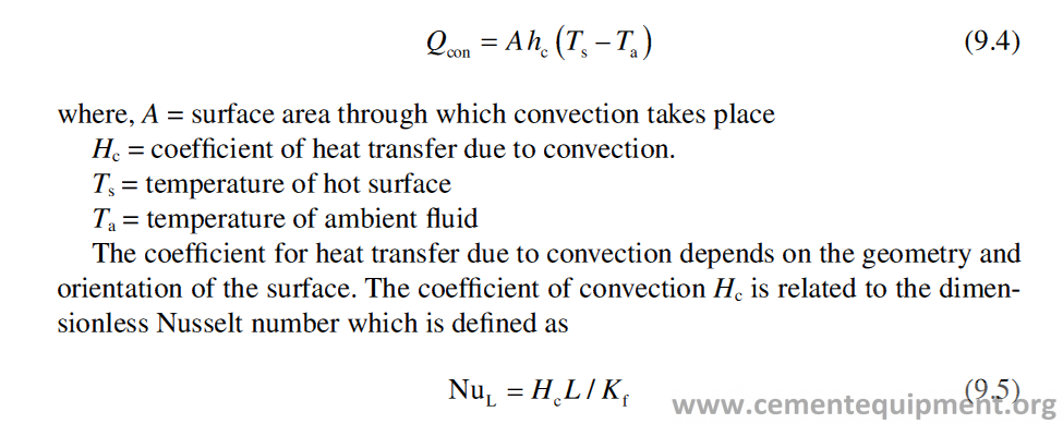
where L is the characteristic length of the body and Kf is the thermal conductivity of surrounding fluid, which is air in this case. The Nusselt number can be related through empirical data to other properties of the convective fluids.
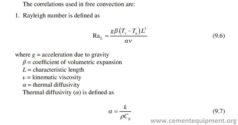
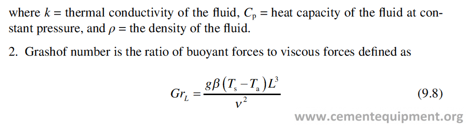
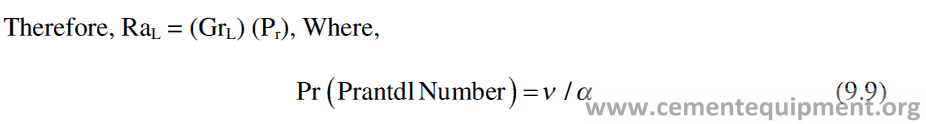
There are two different kinds of fluid (air) flow around the object from which the convective heat transfer occurs. The flow may be laminar or turbulent. The laminar flow is an orderly flow of fluids where the fluid layers are parallel to each other, and turbulent flow is a disorderly flow where the fluid layers cross each other and are never parallel. The laminar flow generally occurs with fluid flows at low velocity, and turbulent flow occurs when the fluid moves at high velocity. Figure 9.3 shows how the laminar and turbulent flow looks like. The type of flow can be characterized by the Rayleigh number: for laminar flow, the Rayleigh number is below 109, and for turbulent flow it is above this figure.
The calculations of free convection and Nusselt number for objects with different geometries are as follows.
Vertical Wall
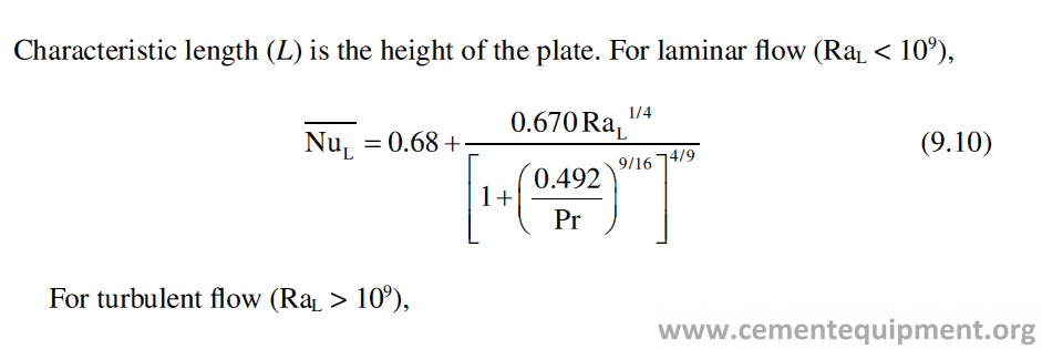
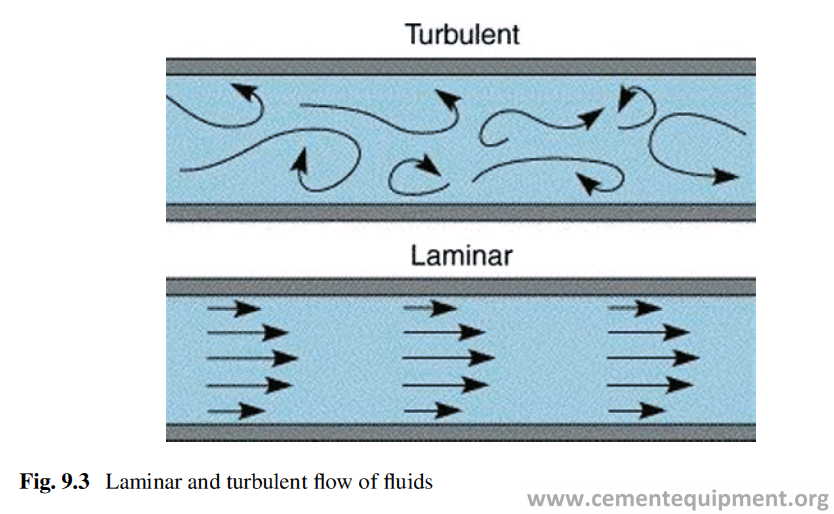
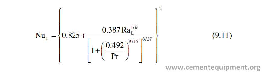
Horizontal Wall
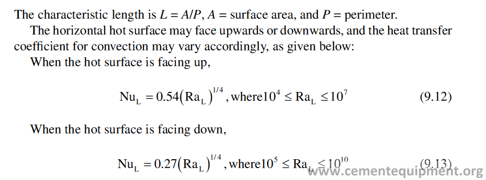
Vertical Cylinder
The equation for vertical plate is applicable if the thickness of the free convection boundary layer is much smaller than the cylinder diameter. The cylinder may be considered as vertical wall of breadth equal to the circumference of the cylinder.
The criteria are given quantitatively as D/L ≥ 35/ (GrL)1/4, where D and L are the diameter and length of the cylinder.
Horizontal Cylinder
Characteristic length is the outer diameter of the cylinder, Do:
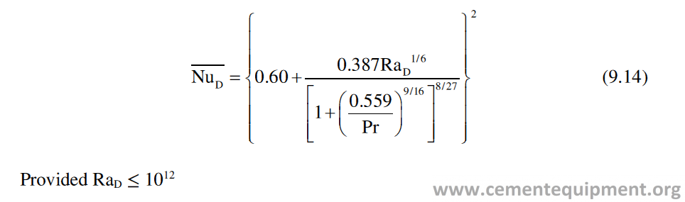
If we want to calculate the heat loss per square meter, due to convection from the outer surface of the rotary kiln of diameter 6 m, whose outer shell temperature is at 350 °C in the burning zone, then we can calculate it with the help of the different equa-tions shown earlier. We can calculate the value of RaD using Eqs. 9.8 and 9.9, where we have to consider the value of L (characteristic length) as the outer diameter of the shell. If we consider the ambient temperature as 30 °C, then the average temperature of kiln shell and ambience is 190 °C. We must consider the values of β, α, and ν at that tempera-ture which are available in standard literature. Putting the values we get RaD = 4.72 × 10¹¹, which is less than 1012; therefore Eq. 9.14 will be applicable here.
We can now get the value of NuD from Eq. 9.14, putting the value of RaD and Pr, which comes as 835.38. Putting the value of NuD in Eq. 9.5, we can calculate the value of hc as 5.012, and using the value of hc, the value of the convective heat loss can be obtained from Eq. 9.4, as 1603 watt per square meter. This calculation, although, an approximate one, because in actual operation the kiln is not a static body and rotates slowly which changes the heat transfer coefficient, but gives a fair idea about the heat transfer taking place. For more accurate treatment on this subject the technical paper on this subject [4] may be consulted.
Radiation
Any substance at temperature above absolute zero emits thermal radiation indepen-dent of external agencies. This radiation moves in straight line. Thermal radiation moves through the empty space and is not transformed into heat till it meets the matter on its path. Part of the radiation is reflected by the body, part is transmitted through the body, and the part is absorbed by the body. It is only the absorbed energy that appears as heat. Heat transfer from a body by radiation does not need any medium unlike conduction and convection. Radiation heat exchange happens between two bodies at two different temperatures. The heat is exchanged from both, the body at high temperature to low temperature and from body at low temperature to high temperature, with net transfer of heat energy from the body at high tempera-ture to low temperature. Thermal radiation occurs from the surface of the body and is a function of the surface temperature and surface characteristic. Heat loss from a process equipment due to radiation becomes very significant, when its temperature is considerably higher from the ambient.
If the surface temperature of a body is Ts and the ambient temperature is Ta, then the heat transfer from the surface is given by the equation below:
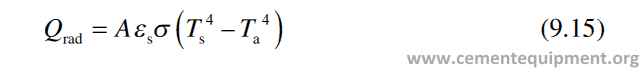
where εs is the surface emissivity and σ is Stefan-Boltzman constant and A is the surface area available for heat transfer.
All objects at temperatures above absolute zero emit thermal radiation. However, for any particular wavelength and temperature, the amount of thermal radiation emitted depends on the emissivity of the object’s surface. Emissivity is defined as the ratio of the energy radiated from a material’s surface to that radiated from a blackbody (a perfect emitter) at the same temperature and wavelength and under the same viewing conditions. It is a dimensionless number between 0 (for a perfect reflector) and 1 (for a perfect emitter). The emissivity of a surface depends not only on the material but also on the nature of the surface. For example, a clean and pol-ished metal surface will have a low emissivity, whereas a roughened and oxidized metal surface will have a high emissivity. The emissivity also depends on the tem-perature of the surface as well as wavelength and angle. Table 9.1 gives the emissiv-ity values of some material.
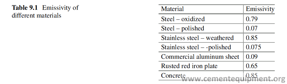
Heat Loss Calculation
Let us calculate the heat transfer per square meter through radiation from a rotary kiln shell at 350 °C to ambience and at 30 °C using Eq. 9.15.
Qrad = 0.79 × 5.669 × 10−8 × [(350 + 273)4 – (30 + 273)4] = 6369 Watt, where Stefan-Boltzman constant = 5.669 x 10⁻⁸ w/m2K4.
Combined Heat Loss by Conduction, Convection, and Radiation
In industrial furnaces the heat loss from the furnace takes place through combined heat transfer process where all three different forms of heat transfer work simultane-ously. As per this process, as shown in Fig. 9.4, the heat from inside the furnace or any process equipment comes to the outer shell by conduction through Refractory lining, and then the heat is lost from the surface both by convection and radiation.
If the inside temperature of the furnace is Tf and the shell temperature becomes Ts, at steady state or at equilibrium, then, Qcond = Qconv + Qrad, where Qcond is the heat transferred, from furnace inside to outside shell, Qconv is the heat transferred by con-vection from outside shell to ambience, and Qrad is the heat lost from outside shell by radiation. Therefore we can write it, as This equation is used to calculate the refractory thickness and the outside shell temperature in the actual practice. In this equation Ts depends upon D1, D2, K1, and K2 which are all variables. For this reason, it is not possible to solve this equation to know Ts. However, for a certain combination of quality and thickness of refracto-ries, Ts (shell temperature) can be found out by a trial and error method.
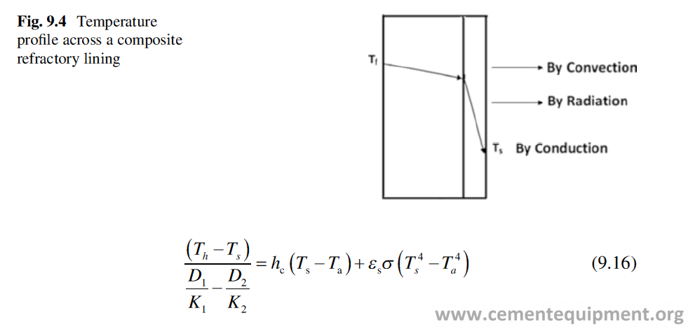
In the calculation process, first the refractory qualities are to be decided, and then certain values of D1 and D2 are to be decided. A probable value of Ts is to be decided, ambient temperature Ta is to be considered, and then it is to be seen whether the value of the left side of Eq. 9.16 equals to the right side of Eq. 9.16, and thus, by trial and error, the right value of Ts is to be chosen which will satisfy Eq. 9.16. Nowadays softwares are available which on putting the values of different variables give imme-diately the value of Ts, heat flux, etc.
The above discussion shows that if the surface temperature of the kiln and its other accessories, wherever possible, can be reduced, then heat loss both due to con-vection and radiation can be minimized. Study shows that kiln temperature does not remain constant and fluctuates. The degree of fluctuation gets reduced with higher rotation speed of the kiln and the fluctuation is independent of kiln diameter [5].
Energy Loss Norm Through Different Equipments
A detailed energy audit was made on a 3.60 m diameter dry process kiln, and the total energy consumed or lost through different equipments is given in Table 9.2 [6].
The below data indicates a good amount of energy is lost through the radiation and convection from the kiln shell. Figure 9.5 shows the actual heat loss map along a rotary kiln length, from inlet to discharge end [7].
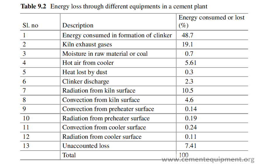
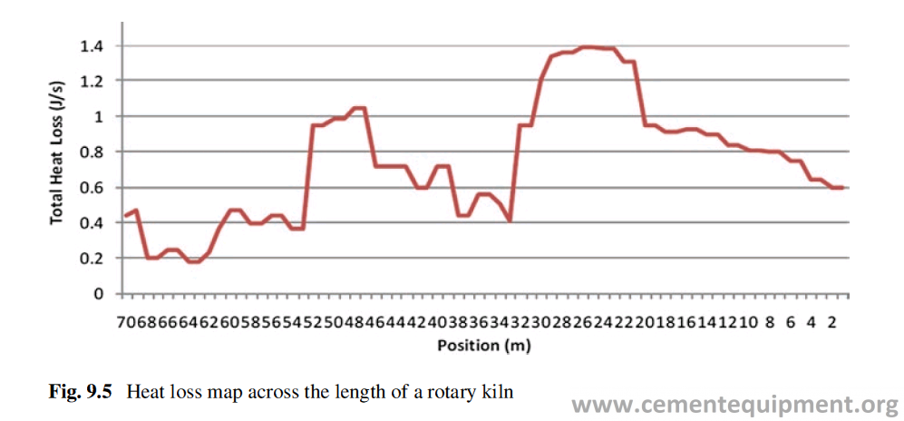
Use of Insulation in Rotary Kiln
To reduce this energy loss, the use of backup insulation lining is not suggested, because, if the backup insulation refractory is used, the temperature profile across the working lining brick thickness will become flatter compared to the lining with-out insulation (Fig. 9.6). The result will be deeper penetration of the clinker liquid phase, before the liquid phases cross the temperature zone, where those freeze to solid phases.
Because of this change in temperature profile, the corrosion of refractory will get enhanced when insulation is used as backup lining in kiln and the lining life will come down, which will ultimately result in kiln shutdown. The deeper infiltration of liquid also causes the alteration of structure leading to failure due to thermal shock.
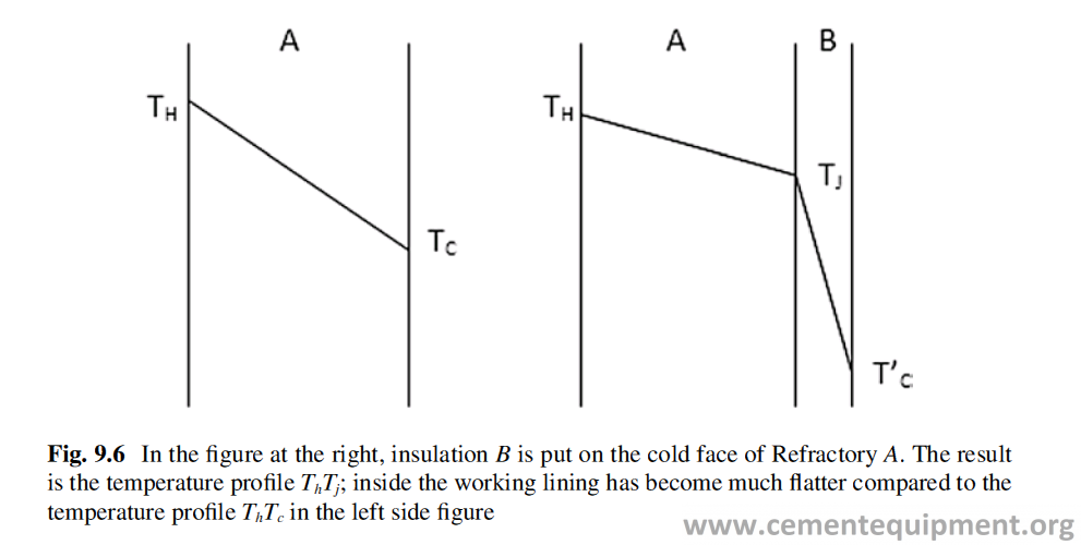
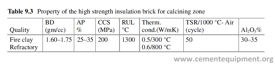
Moreover when the backup insulation will be used in the burning zone, because of the changed temperature profile (Fig. 9.6), the viscosity of the infiltrated liquid phases will remain low, and as a result the coating will be thin and unstable, and the advantage of using insulation will be offset by the less coating thickness. Another problem may be encountered is the relative movement of the two layers of refracto-ries during rotation of the kiln.
When insulation brick is used as a backup lining, if the kiln preheating is done fast, the insulation brick at the backup lining will experience a very high compres-sive stress generated from the expansion of working lining, which may crush the insulation layer to make the lining unstable.
In the calcining zone, the high strength insulation bricks can be used. These bricks are aluminosilicate Refractories with Al2O3 ranging between 30% and 35% and have higher porosity, lower density, and fairly good resistance to abrasion. The aluminosilicate material has inherent low thermal conductivity, and because of higher porosity, the thermal conductivity becomes further less, which helps to retain the heat inside and conserve energy. Moreover because of lower bulk density, these bricks store less energy in heating up the process and reduce the energy require-ment. The property of this kind of refractory is given in Table 9.3.
Criteria of the Use of Insulation
Although a relatively small portion of the heat is lost from the preheater and cooler because the cement manufacturing is made in a very large scale, the small propor-tion of energy saved amounts to a large quantum of energy over a long period of operation. This is the reason that large amount of insulation Refractories are used in the other equipments also like preheater cyclones, cooler, etc. in the cement plant.
The effectiveness of insulation refractory follows the rule of diminishing returns. The use of more amount of insulation refractory may not be economical. If, for example, more insulation thickness is used inside the cyclone, its effective volume will be reduced.
Therefore to keep the inside volume same, the cyclone diameter must be made higher, which involves more cost, and that may not be proportional to the benefit obtained by increasing the thickness of the insulation (Fig. 9.7).
A portion of the gas, inside the furnace, permeates through the pores, fine cracks, and gaps to reach up to the steel shell. When the furnace atmosphere contains the corrosive gases like SO3, HCl, etc., care must be taken to control the shell tempera-ture above the dew point of the gas, because if any condensation takes place on the shell, it will corrode the shell because of the acid formation due to dissolution of SO3 or HCl in water and may pose serious problem. Therefore during the use of insulation, care must be taken to see that the temperature of shell does not fall below the dew point of the gas [8, 9].
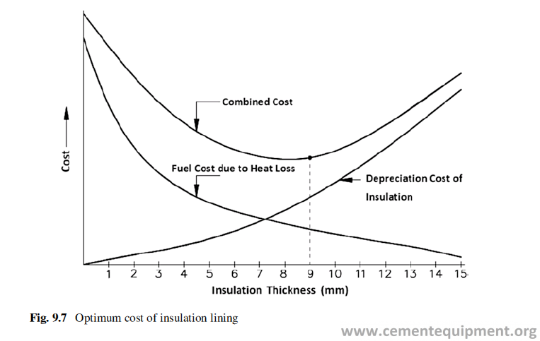
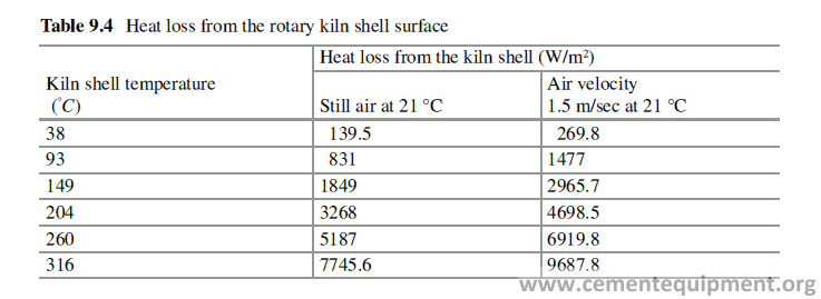
Therefore to determine the economic and technically viable thickness of insula-tion, the following points must be taken into consideration:
- Cost and calorific value of fuel
- Insulation refractory, quality, and price
- Surface temperature targeted
- The thickness and quality of working refractory
- Duration of operation on annual basis
- Ambient temperature
- Surrounding wind velocity
- Dew point of the gas inside
- The equipment where it will be used
All the previous calculations are based on the assumption that the ambient temperature is 30 °C and wind velocity is zero. But in actual practice the ambient tem-perature varies. The lower is the ambient temperature, the more will be the heat loss. On the other hand, the more will be the wind velocity, more is the heat loss. Table 9.4 gives the comparison of heat loss when the air is still and when its velocity is 1.5 m/sec [10].
The painting of low-emissivity paint on the outside kiln surface can reduce the heat loss due to radiation. A study [11, 12] showed that the painting of a kiln outside surface, with a paint of emissivity 0.5, reduces the radiation losses by 9%. But the surface temperature is increased by 59 °C, over 332 °C for an unpainted surface. Due to this increase of temperature, heat loss due to convection will increase, but heat loss due to radiation will decrease, and the net effect is the reduction in thermal loss and fuel saving.
Management of Quality and Inspection
Introduction
The refractory is a very important part of a new cement project. The successful com-missioning and running of the project depend to a great extent on the design and selection of the refractory, the quality management of the products [1], and its instal-lation. The execution of the process of refractory procurement and installation varies from country to country. In some country, the design of refractory lining is made by the technology provider or the consultant or a third-party service provider, and sub-sequent procurement is made by the user company, who procures it directly, and the installation service is outsourced. In other countries the refractory design, procure-ment, and installation are outsourced through a Refractory engineering company.
There can be different models for execution of the refractory lining job suiting to work environment and work culture of a particular country.
Quality Management
This covers the management of the quality of the refractory from the handling of the inquiry to the termination of the warranty period as shown in Table 10.1 (as a sam-ple), and these activities are applicable for project execution.
All procedures during this period to achieve the successful performance of the refractory are reviewed and included in the quality management. The total activities of quality management system for Refractories can be subdivided under different headings and can be elaborated as given in Table 10.1. The total activities of quality management system for Refractories depend upon the volume and complexity of specific project as shown in Table 10.2.
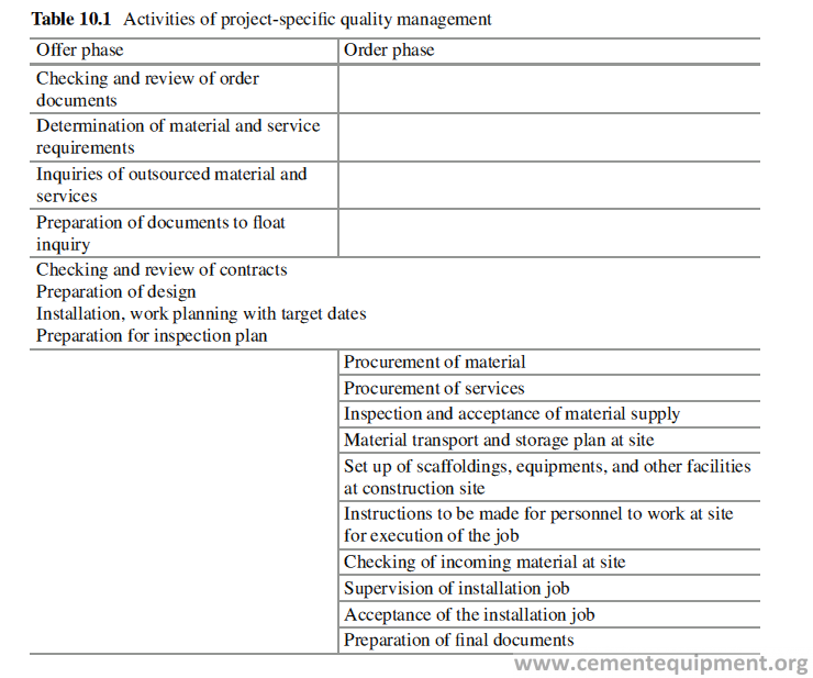

Inspection Plan: General
A test/inspection plan helps to assist planning and documentation of the inspection
procedures. It is required to record these activities in a suitable manner to provide the understandable and reliable documents. The more detail are the information kept, better it is to analyze and rectify any problems faced later. The details may be as follows:
- Documentation to track flow of
- Drawings with records of revision updates.
- Proof of inspection of incoming materials with test reports.
- Construction site report to track on-site acti
- Inspection plans and related inspection reports.
- The inspection plan should also contain instruction on the procedure to follow if defects are noticed.
Inspection Plan for Procurement of Material
During the design stage, refractory lining material, for any equipment, is already
specified, both by quality and by design. Based on the technical data provided in the design, the refractories are procured. Therefore, before the inspection, the following information must be available:
- The refractory design and drawing
- Specifications of the refractory
- The test methods to carry out tests against the different specification parameters
- Specification of packaging
- Sampling plan to be followed
The purpose of inspection is actually to inspect the procured material for accep- tance. The quality inspection is done to determine if and to what extent the products fulfill the quality requirements. For quality inspection, the sample is drawn from a population, called lot. The tests are conducted to check if the quality characteristics are being achieved, as agreed upon between the supplier and the buyer.
Inspection of Materials
The quality inspection is done to determine if and to what extent the materials fulfill the stipulated quality requirements. Quality inspection is conducted based on the samples taken from a finite population called lot. Two different types of inspections can be there, one is by attributes and the other by variables. For the inspection by attribute, the countable inspection parameters, e.g., corner breakage, body crack,etc., in the inspection lot are determined. It is required that manufacturer and con-sumer agree on the definition of the defects and acceptable quality level (AQL).
The inspection by variables is based on the measurable quality parameters, e.g., bulk density, porosity, cold crushing strength, etc.
Inspection for acceptance of the shaped Refractory materials always involves inspection by both attributes and variables, whereas unshaped Refractories are inspected by variables.
Shaped Refractory Materials
For shaped refractories ISO 5022 provides sampling and inspection procedures both by attributes and variables according to which samples can be drawn to get the best uniformity of the refractory materials being supplied. For inspecting a lot, there are two inspection procedures, independent of one another.
– Inspection by attributes which is a nondestructive test.
– Inspection by variables which is a destructive test.
The following information must be recorded during sampling and accepting check:
- Description of materials
- Number, designation, and the size of the lot Date and location of sampling
- Number of pallets per brick item
- Number of samples for inspection by variables, with indication of item designation
- Random sampling plan evaluation criteria, for the agreed properties
- Agreed properties and guaranteed values of the same as the criteria for evaluation
- Documentation of all results for inspection by attributes and acceptance report.
Inspection by Attributes
The process adopted here is a nondestructive test, and the sample plans are as per statistical procedure because the sample size is large. The following parameters are checked while inspected by attributes.
Sonic – Inner defects, like lamination, can be found out by hitting the bricks with a suitable steel hammer with wooden handle. The sound is usually different and dull when there is defect like lamination or crack inside.
Edge strength – Edges and corners of the bricks must be strong and tight. The grains must not come out when rubbed with thumb. The number of edge damage must not exceed an agreed limit.
Burn cavities – Although it has no technical significance, bricks with large cavi-ties, area-wise and depth-wise, are not acceptable.
Cracks – Bricks, which only have surface cracks and generate good sound on hammering, are not treated as defective. The fine surface cracks are the result of firing behavior of that specific product, out of coarse-grained ceramic material. The brick may be cut in case of doubt to see the penetration of the crack. The small crack on the surface opposite to the non-working surface may be ignored.
Brick texture – The texture of the brick can be assessed by observing the frac-tured surface. Usually the breakage of the coarse grains suggests the matrix is strong and the brick is fired well. The texture must not contain any defects such as inner cracks or void areas.
Dimensional accuracy – The dimensional accuracy must be checked keeping in mind its installation procedure. Any warpage in the brick must also be checked which may pose serious problems during installation and service. Sometimes the bricks may be lined to see if proper circle is made, e.g., in case of kiln bricks.
Sampling for nondestructive tests
When a material is offered for inspection, the total material of the same quality and size, having a comparable properties and characteristics, is called a lot. A portion of the lot is called sample. The sampling procedure is very important and the sample must represent a lot. Normal sampling procedure is, for example, to draw few bricks, without any justification to the number, from a certain lot, and to test those bricks to see whether the test result matches to the specified values. But the sam-pling should be done scientifically with a purpose. Acceptance sampling procedure is a scientific method of sampling and involves the interest of both producer and consumer. Consumers need acceptance sampling plan to limit the risk of rejecting good-quality materials or accepting bad-quality materials. Two levels of quality are considered in the acceptance sampling plan.
The first is the acceptable quality level (AQL), or the quality level desired by the consumer. The producer of the item strives to achieve the AQL, which typically is written into a contract or purchase order. The producer’s risk (α) is the risk that the sampling plan will fail to verify an acceptable lot’s quality and, thus, reject it. Most often the producer’s risk is set at 0.05, or 5 percent.
Although producers are interested in low risk, they often have no control over the consumer’s acceptance sampling plan. Fortunately, the consumer, also, is interested in a low, producer’s risk, because sending good materials back to the producer
- disrupts the consumer’s progress of project or production process and increases the likelihood of shortages in materials, 2. adds unnecessarily to the lead time for finished products or services; and 3. creates poor relations with the producer.The consumer’s risk (β) is the risk that the sampling plan will fail to verify a rejected lot’s quality and will accept it. A common value for the consumer’s risk is 0.10, or 10 percent.
All sampling plans are devised to provide a specified producer’s and consumer’s risk. However, for the interest of the consumer, it is best to keep the average number of items (properties) (ANI) inspected to a minimum, because that keeps the cost of inspection low.
Sampling plans differ with respect to ANI. Three often used attribute sampling plans are, the single sampling plan, the double sampling plan, and the sequential sampling plan.
But for refractory products, single sampling plan is most appropriate. When the lot is very large, it can be subdivided into few smaller lots to minimize the risk of rejection.
Sampling plan
In this method the samples are drawn to test defects, like cracks, dimensional intol-erances, firing defects, etc.
AQL (acceptable quality level) is the acceptable proportion of defective items in a lot and is fixed by agreement between the supplier and the consumer. Table 10.3
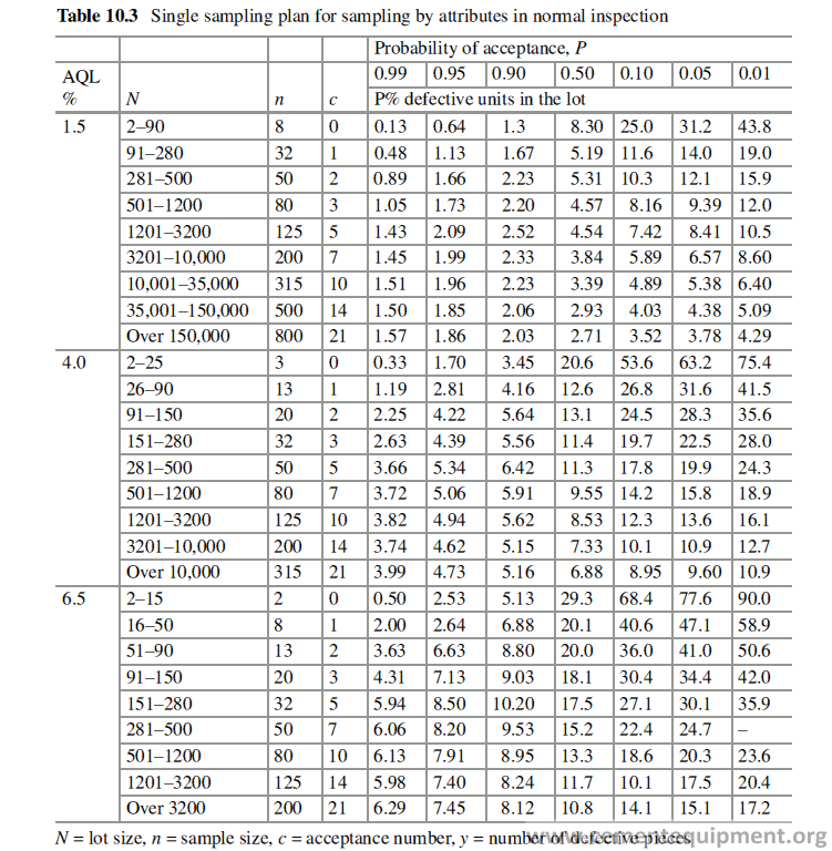
gives the sampling plans [2] for AQLs of the order 1.5, 4.0, and 6.5 as per ISO-5022. This table also gives in column 4 the probability of acceptance P for different pro-portions “p” of defective units in the lot.
The number y of defective pieces in the sample, having size n, is determined. If y < c, the batch is in conformity. If y > c, the batch is not in conformity.
When the lot size is big, it can be divided in smaller sublots to avoid the risk of rejection of a good lot or accepting a bad lot.
For example, a consignment of total mass of 120 tons comprises of 15,000 pressed bricks. The consignment can be divided into three lots, say:
Sublot 1 – 2000 Pcs
Sublot 2 – 1000 Pcs
Sublot 3 – 9000 Pcs
As indicated in Table 10.3, in case of sublot 3, for example, the sampling plan used provides AQL 1.5%.
For the producer the risk of having a batch which contains 1.99% of defective pieces erroneously declared not to be in conformity is equal to 5%.
For the consumer the risk of having a batch which contains 5.89% of defective pieces erroneously declared to be in conformity is equal to 10%.
The inspection process is given in table below (Table 10.4).
Inspection by Variables
By this inspection method, the measurable refractory properties are inspected. During selection of the properties to be inspected, it is preferred to select a property whose testing is easy, can be done quickly, and is inexpensive. If more than one property is to be measured, then it is to be seen that the selected properties are inde-pendent of each other.
ISO 5022 offers several sampling plans to assess the uniformity of a product. These are:
1- Inspection in case of guaranteed value for the mean value and a known standard deviation
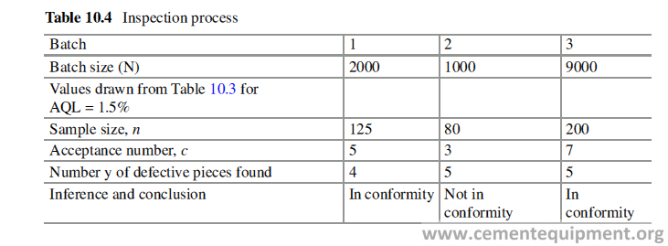
- Single sampling plan with a fixed limit for individual values and a known standard deviation
- Single sampling plans in the case of a guaranteed value for the mean and an unknown standard deviation
- Single sampling plan with fixed limit for individual value and an unknown stan- dard deviation
Sampling for Destructive Tests
Refractories are heterogeneous material made out of mixing of ingredients in solid state, followed by forming and normally high-temperature firing in case of shaped products. Refractory quality specification comprises of both chemical specification and physical specification, and during inspecting a product, the con-sistency of its chemical as well as physical properties needs to be checked. When product batches are manufactured over a small period of time, the chemistry does not change much, and it remains within fairly close limit. Therefore the variation in chemistry due to raw material, during manufacturing a lot over a small period of time, is not significant.
The consistency of physical properties of refractory shaped products depends on many factors, e.g., the uniformity of mixing of ingredients and the consistency of forming and firing. If those process parameters are consistent, the properties of the refractories, also, will be consistent. For checking the consistency of properties, one need not to check all the properties like porosity, density, RUL, thermal conductiv-ity, thermal shock resistance, permanent linear change, etc., because it takes time and will be expensive also. The consistency of products can be very well ascertained by the density and porosity check, which are very easy and fast. The soundness of the forming process and high-temperature firing process is reflected in its density and porosity. If the products are made with inconsistent forming and without main-taining proper firing process parameters, the density and porosity values will also be inconsistent. The other properties can be checked by drawing random sample and carrying out the tests, and if the density and porosity values are consistent, then those values also will be consistent over the whole lot.
The Sampling Plan
The sampling plan is applicable when the guaranteed value of the mean value (μG) and standard deviation (σ) value are available. The producer and consumer must agree to those values. A single sampling plan is characterized by the sample size n, and the acceptance factor KPRE and the figures are available in Table 10.5 [3].In this method the test of n samples yields n individual values, and the mean (Xm) of those values is calculated.
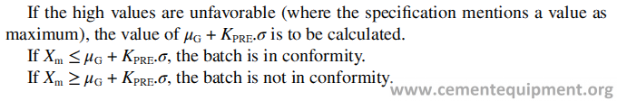
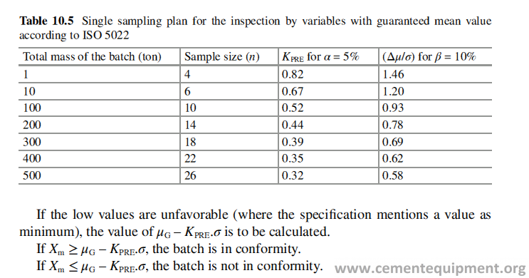
Example
Let a 300 ton batch of refractories to be inspected for acceptance with respect to bulk density. Let μG = 3.00 gm/cc be the guaranteed mean value agreed upon. In view of the given data as per Table 10.5, sample size is 18 and the acceptance factor KPRE = 0.39. The mean of the 18 test results is Xm = 2.99gm/cc, and standard devia-tion is determined as 0.05 gm/cc.
The following is the calculation method to conclude whether the lot conforms the guaranteed mean value.
Low values of bulk density is unfavorable to the refractory quality; therefore the value of μG – KPRE.σ is to be determined, and this will be equal to 3.0–0.39 × 0.05 = 2.98. Since Xm ≥ μG – KPRE.σ, the batch conforms the quality.
In this sampling plan, the producer’s risk of having a batch, the true mean value of bulk density of which would be 3.00 gm/cc, declared not to be in conformity is 5%.
The consumers’ risk of having a batch, the true mean of which would be μG –(Δμ/σ) = 3.00–0.69 × 0.05 = 2.96 gm/cc erroneously to be declared to be in confor-mity, is 10% (β).
Unshaped (Monolithic) Refractory Materials
For unshaped Refractories only an inspection by variable is done. Sampling of monolithic refractories is described in several standards like DIN EN 1402-2 and ISO 8656-1. The procedure can take much time and is often expensive. Let us describe the sampling procedure as per DIN EN 14402-2.
Before starting the sampling procedure, the following points must be recorded:
- The inspection lot must be determined.
- The type and weight of the packaged item must be established. For example, whether it is small bag, big bag, carton, block materials, cans, etc.
- Form of delivery of packing, for example, pallets. The number of pallets must be determined and they are numbered.
The method of sampling will depend on the type of packing. It will not be same for 25 kg bag and 1 ton big bag.
The properties for assessing uniformity of the product must be determined beforehand. In cement industries the monolithic refractories mostly used are con-ventional castables, low and ultra-low cement castables, insulating castables, gun-ning, and shotcrete materials and mortars.
The typical properties to be investigated for castables are:
– Water requirement to get the desired consistency
– Workability and setting time after casting with desired amount of water
– Bulk density of the castable after casting and drying at 110 °C
– Cold crushing strength after casting and drying at 110 °C
– Permanent linear change after heat treatment at a certain temperature
And for Refractory mortars, the typical properties to be investigated are:
– Sieve analysis
– Main chemical constituents
– Setting behavior
The criteria for acceptance or rejection of an inspection lot must be agreed upon beforehand by both producer and consumer. The agreed guaranteed value for the specific property, for example, the mean value or the one-sided limit for the indi-vidual property, must be decided.
The total inspection process consists mainly of four steps:
- Drawing the sample
- Reduction of testing sample from the main sample by coning and quartering
- Making the specimen samples of bars or cubes for testing
- Evaluation
Drawing the Sample
Before the start of the sampling, the inspection lot must be determined. It must be decided that whether the whole of the supplied lot will be considered as inspection lot or it is to be divided into smaller lots for inspection purpose.
Sampling from the sacks is to be done by an awl. For fine-grain products, an awl is to be used. The diameter of the awl should be at least three times larger than the maximum grain size of the product. For coarse-grain products, small hand-size sam-ple shovel is to be used. Sampling from the big bags is done by emptying the big bag.
Reduction in Sample Size
The amount n of individual samples from the packaged products, which make up the sample for testing, is to be determined. For items with packing below 35 kg, the sampling plan according to ISO 5022 can be used. The amount n will depend upon a guaranteed mean value, with known or unknown standard deviation, for a particu-lar property, as shown in Table 10.5.
For items having packing more than 35 kg, however, it is recommended to deter-mine the sample size on the basis of statistical inspection plan, for example, accord-ing to ISO 8656-1. The amount n of single samples from packaged products will depend on the magnitude of the variation coefficient v of the property to be inspected as per plan given in Table 10.6.
The value of v is determined from the relation, v = 100 σ/m in %. Here σ is the standard deviation and m is as per the column 4 of Table 10.6. If several properties are examined, then the property with the highest variation coefficient is decisive for determining the amount n of single items from packaged products. If v is unknown, then the amount is chosen according to Class 3.
The single samples from packaged products are formed from p elementary single samples. In practice six elementary single samples per packaged item have proven sufficient. The minimum amount of single samples from packaged products is determined according to the maximum grain size as described in ISO 8656-1 (Table 10.7). According to DIN EN 1402-2 and ISO 8656-1, a sack of 35–50 Kg is a single sample of a packaged product. This however leads to huge sampling amount and is of no sense, for example, for a lot size of 100 tons, the sample will be 0.5 ton.
The collective samples therefore are homogenized and then divided up with a splitting cross or riffle sampler into a lab collective sample. With this smaller amount, the test samples are prepared for inspection.
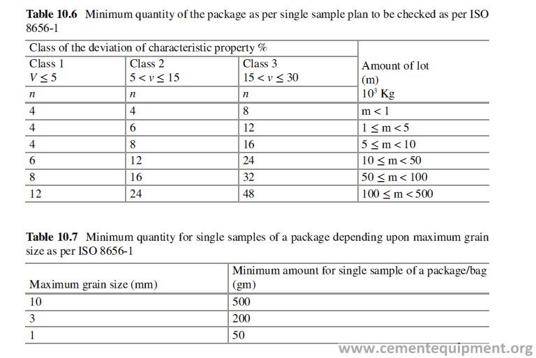
The samples of refractory castables test pieces are made by vibrating, self-flowing, or poking depending on its type and actual use.
The samples can be made following ISO, DIN, or ASTM standards. Steel molds are used to give the shape to the castable after it is mixed with water.
For gunning mixes, the gunning is done inside a steel former as shown in Fig. 10.1 [4]. After gunning the castable is allowed to be cured for 24 hours. Then the test sample bars are cut out of the gunned mass as given in Fig. 10.2. The physi-cal properties of castables are inspected according to DIN EN 1402-6 or DIN EN 1402- 7, and physical properties of mortars are done according to PRE/R43 or DIN1089- 3. It is to be borne in mind that some properties of refractory castables, for example, CCS, are dependent on the size of the sample.
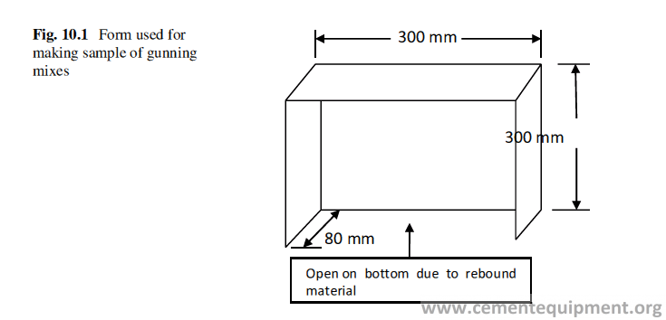
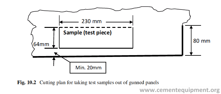
Evaluation
The evaluation procedure for making a decision in favor of acceptance or rejection is done following the method shown in the sampling plan for destructive testing (page no 214–215).
Mortars
For mortars a limit value Xmax or Xmin is agreed upon to assess the conformity of the product under inspection. The lot is accepted if a single individual value of the col-lective sample does not exceed or fall below the agreed limit value Xmax or Xmin.
Inspection of Installation
In previous sections the inspection plan of refractory materials is discussed which ensures quality of materials to be installed.
But properties of refractory lining do not depend on the refractory quality alone. It is also very important that the instructions for the material preparation and lining methods are followed meticulously to get a sound lining. The inspection plan shown in Table 10.8 provides a framework for the quality assurance of the refractory installa-tion work. Specific aspects of the inspection plan are discussed in further detail below.
Inspection Plan for Installation of Refractory Materials
Test and inspection connected to installation of refractory materials are very com-plex, and a great amount of experience is required to set up effective inspection plan. It is to be framed looking into the particular situation prevailing at the site. Table 10.8 shows the content of a sample inspection plan.
An inspection plan can be outlined as follows:
- Preliminary inspection or the check before the start of the work
- The checking of the technical documentation
- The measurement and checking the appearances of the supporting steel construction
- The inspection of incoming refractories, material, storage condition, and transportation arrangement to the construction site
- The availability and readiness of equipment, machinery, scaffolding, etc. The qualification of the work force
- The safety measures
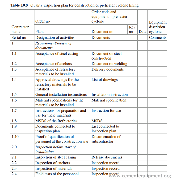
Installation inspection or the inspection during installation work
- The observance of engineering requirements, e.g., dimensions, arrangement to fix the forms, expansion joints, etc.
- The observance of the instructions for the preparation and use of the refrac- tory material, especially when installing the unshaped refractory materials
- The records and measures to trace back, proof of installation
- The inspection after the installation work
- The evaluation of results for sampling procedure
- The acceptance by the customer
For each part of the construction, preparation of an inspection plan is recom-mended keeping the points mentioned above in consideration. The entire inspection plan for the installation of the refractory materials is based on a list of all the construction parts. For each construction part, an inspection plan is to be made which will be connected to the inspection reports.
Technical Documentation and Installation Manual
All technical information pertaining to the material specification and instructions for installations should be collected and put in a file as an installation manual. This manual should be with the manager in charge of installation at the site. The instal-lation manual must contain the following information:
– The detail drawing of the refractory lining of the equipment
– The list of all the parts of the equipment
– All material data sheets
– General installation instructions, with requirements of machineries, tools and tackles, design and arrangements of joints, lining around retainer plates, etc.
– Installation details with details of expansion joints
– Any specific working and installation instructions with installation sequences, local condition, etc.
– Details of installation with details of castable curing and drying up and preheat-ing procedure
– Quality inspection plan for material and installation job including anchor weld-ing, anchor spacing, and orientation
The completeness and revision updates of the documents must be checked by the site manager upon the receipts of documents.
Preliminary Inspection of the Construction Part
The inspection of the supporting steel construction deals with the measurements of length, height and width, ovalness, design of openings, and the arrangements of anchors.
The anchor strength, spacing, orientation, and the surface must be checked for dirt, coating, rust, etc. Table 10.9 shows the way the inspection of welding of anchors is to be recorded.
Inspection of Incoming Material, Its Storage, and Transportation to the Site
Based on the technical documentation, the site manager checks the supplies arriving at the construction site. Next important issue is to mark the material properly and to store safely till those are used. The incoming and outgoing material should be docu-mented separately.
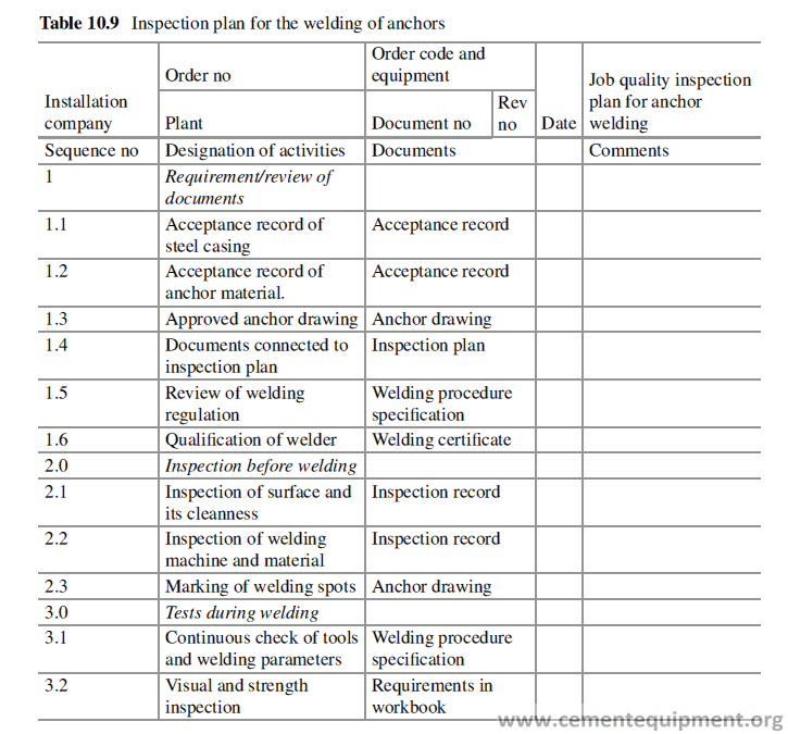
Readiness of the Equipments and Utilities
It is to be checked before start of the work that which things are in the scope of the contractor and which are in the scope of the customer and accordingly the arrange-ments for scaffolding, power, water, compressed air, etc. are done. Safety measures to be taken are also to be reviewed.
Qualification of Personnel
It must be ensured that the personnel engaged at the site are well trained and are familiar with the work to be carried out. For example, for gunning installation of the castable, a man should be engaged having good experience in that job.
Compliance with Engineering Requirements
The engineering requirements for installation of a Refractory lining are of special importance for successful campaign life of a refractory lining, and the proper records of those are to be kept. For example:
– Wall thickness of the individual layer and the quality of refractories are to be used.
– Measurements of expansion joints.
– Coating over anchors.
– Insertion of joint material.
– Placement of separation layers.
– Inspection, measurements, and method of fixation of forms before casting of castable lining.
Compliance with Application Guideline
The observation and compliance with instructions for preparation and use, applica-tion, and working must be carefully checked and recorded, especially when mono-lithic refractories are installed. The personnel in charge of installation of the monolithic refractories must be equipped with special instructions. The following mixing records must be maintained:
– Ambient temperature and humidity
– Temperature of the mixing water
– Quantity of the material and the mixing water
– Mixing time
– Pot life
– Setting time
If the material is installed by gunning, a gunning experiment should be con-ducted before the actual start of installation.
Inspection of Preheating Arrangements
Preheating is a very important part in the whole installation process of the refrac-tory. Preheating schedule of temperature vs time is the first document required to start the process. The following must be checked and set up as a part of the prepara-tion to start preheating:
– The supply lines for oil or gas as fuel.
– Fan and blowers of required capacity.
– Pumps of required capacity in case of use of fuel oil.
– Number of burners and the defined openings where those are to be fitted.
– The total heat input required to heat up the equipments and the heat delivered by the burners should be checked beforehand.
– Specified location points for installing the thermocouples. The thermocouples must be projected about 80–100 mm inside the equipment chamber.
– The tightness of the oil or gas lines must be checked thoroughly to ensure no leakage.
Final Inspection and Acceptance
The completed installation job, done by the principal contractor or subcontractor, must be inspected thoroughly before acceptance by the customer. The inspection must be continuous along with the progress of the installation job, especially in case the construction job is very big. The quality report of inspection of installation job can be summarized in Table 10.10 which is very handy, and the whole installation job can be monitored at a glance. Refractory lining is done, normally, at the last stage of commissioning of a new Greenfield Cement project or a new line in the existing plant. Normally, at the end of the project the activities are completed in haste to meet the target date of commissioning. The Refractory lining process usu-ally falls victim to that. But, when a plant is supposed to run for next one year with-out any major shutdown due to refractory, an unnecessary haste may cut short the smooth running of the plant. It is to be remembered that 10% of the refractory fail-ures are due to improper installation. Therefore in the Refractory installation no compromise should be allowed with the quality of installation. Let us remember the old adage that all’s well that ends well.
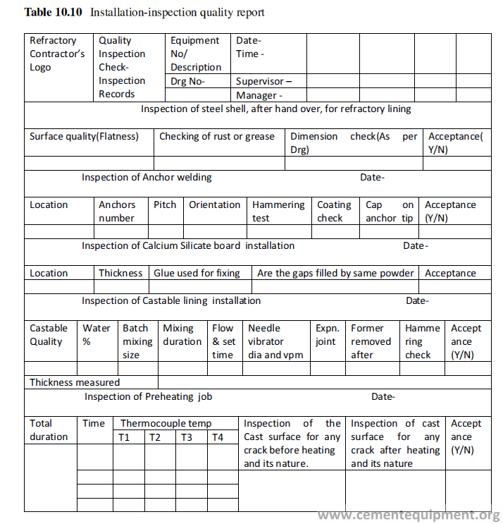
References
Modern Cement Kiln Refractories – Related Insurance risks and Perspective – David Shepherd,
The Refractories Engineer, March 2010.
ISO-5022-79, Shaped refractory products – Sampling and acceptance testing – International Standard Organization, www.iso.org.
ISO-8656-1, 1988, Refractory products – Sampling of raw materials and unshaped products- Part1, Sampling scheme, www.iso.org.
Refractory Engineering – Tech book International, New Delhi, India.
Glossary
Andalusite It is also naturally occurring aluminosilicate mineral containing about
58% Al2O3. Kyanite, sillimanite, and andalusite have almost same alumina con- tent, but they differ in their crystal structure.
Bauxite It is a sedimentary rock containing hydrated aluminum oxide. Refractory- grade and metallurgical-grade bauxites have different characteristics. Bauxite is one of the major raw materials for production of high alumina refractories.
Calcium-aluminate cement Calcium aluminates like CaO·Al2O3, CaO·2Al2O3, etc. have hydraulic properties, and they set and become hard when come in con- tact with water at ambient temperature. These compounds are used for construc- tion purposes.
Chromite It is an iron chromium oxide, FeCr2O4. It is an oxide mineral belonging to the spinel group. Magnesium can substitute for iron in variable amounts as it forms a solid solution to form magnesiochromite (MgCr2O4); substitution of aluminum occurs, leading to the formation of herceynite (FeAl2O4).
Clinkerization The process of clinker formation when the raw meal in cement
rotary kiln is rotated along with kiln shell at high temperature because some liquid formation at high temperature which binds the powder to form cement clinkers.
Cold face In a refractory lining, the face in contact with steel shell or away from the hot face is termed as cold face.
Contact angle The contact angle is the angle, conventionally measured through the liquid, where a liquid-vapor interface meets a solid surface. It quantifies the wettability of a solid surface by a liquid.
Cristobalite It is a high-temperature polymorph of silica. Chemical formula is SiO2. The difference from quartz or other polymorphs is in its crystal structure.
Emissivity The emissivity of the surface of a material is its effectiveness in emitting
energy as thermal radiation. Quantitatively, emissivity is the ratio of the thermal radiation from a surface to the radiation from an ideal black surface at the same temperature as given by the Stefan-Boltzmann law. The ratio varies from 0 to 1.
Eutectic point The point in a phase diagram indicating the chemical composi-
tion and temperature corresponding to the lowest melting point of a mixture of components.
Granulometry It is the measurement of the size distribution in a collection of grains.
Hexavalent chrome Chromium can occur in different mineral and chemicals with different valencies. The chromium with +6 valency is called hexavalent chrome.
Hot face The working face of the lining which is in direct contact with furnace atmosphere and environment is called the refractory hot face.
Kyanite It is a naturally occurring aluminosilicate mineral with about 58% Al2O3.
Liquidus It is the lowest temperature, at which a multicomponent system of solid
metal or its compounds remain in liquid state.
Mullite It is a mineral phase developed in aluminosilicate refractories during its treatment at high temperature. Alumina and silica react at high temperature to form mullite.
3Al2O3 + 2SiO2 = 3Al2O3 ⋅ 2SiO2.
Periclase It is the major component of dead burnt magnesia or fused magnesia.
Chemically, it is a magnesium oxide (MgO) with cubic crystal habit.
Pore size distribution It is the volume percent of pores with different diameter in a refractory body.
Redox reaction Redox reactions are reactions in which one species is reduced and another is oxidized. Therefore the oxidation state of the species involved must change.
Rheological property The flow behavior.
Sillimanite It is also a naturally occurring aluminosilicate mineral containing about 58% Al2O3.
Surface tension Surface tension is the elastic tendency of a fluid surface which
makes it acquire the least surface area possible. The net effect is an inward force at its surface that causes the liquid to behave as if its surface is covered with a stretched elastic membrane.
Thixotropy It is a process of isothermal gel to sol transformation under the influ- ence of a shear stress and the retransformation to gel on withdrawal of the shear stress.
Torque It is a rotational force. Torque is a measure of how much force acting on an object causes that object to rotate
Viscosity Viscosity is a measure of a fluid’s resistance to flow. It describes the internal friction of a moving fluid.
This information it’s very helpful and important for me…