Contents
THE COMPREHENSIVE KILN ALIGNMENT MAXIMIZING KILN STABILITY BY ALIGNING ALL INTERACTING MECHANICAL COMPONENTS
Most kiln alignment procedures fall far short of achieving optimum kiln stability because the applied scope of work is typically inadequate to the task. The purpose of this paper is to detail a comprehensive kiln alignment work scope that achieves maximum mechanical stability.
Seven alignment related procedures are almost always either omitted or are improperly implemented by alignment providers.
1. SUPPORT ROLLER THRUST LOAD MEASUREMENTS
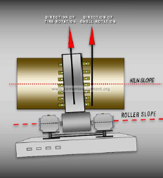
The alignment of support rollers relative to the kiln axis is a very important alignment requirement that is rarely addressed in kiln alignment procedures. If a roller is not parallel to the kiln axis, the direction of rotation of the roller is slightly different than the direction of rotation of the kiln. The undesirable consequences are:
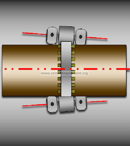
a. In addition to the rotation of the roller along a line perpendicular to the kiln axis, there is an axial roller motion component, resulting in a) high bearing end cap pressures or b) high roller shaft thrust collar pressures, depending on the bearing design. High thrust mechanism pressure in bearings generates heat and thus increases the bearing temperature. Almost all hot bearings are hot because of this pressure condition.
b. High support roller thrust load moves the kiln uphill or downhill, depending on the direction of the thrust load. The cumulative effect of thrust loads on several support rollers can overload a thrust roller. All thrust roller failures are caused by improper alignment between support rollers and the kiln axis.
c. Roller misalignment causes accelerated and uneven wear of tires and rollers. Taper conditions arise that require grinding the tire and roller surfaces.

ROLLERS MISALIGNED RELATIVE TO THE KILN AXIS ARE MECHANICALLY
UNSTABLE. STABILITY REQUIRES THAT ROLLERS BE PARALLEL TO THE
KILN AXIS TO WITHIN 0.008” PER FOOT OR LESS.
The alignment of all rollers has to be evaluated by measuring the support roller thrust loads. This requires the measurement of a) the bearing end cap pressures (AC and Fuller kilns), b) the measurement of the roller shaft thrust collar pressures (FLS and KVS kilns), and c) the measurement of axial bearing pressures (Ahlstrom kilns). If a thrust mechanism pressure exceeds limits set by the OEM, the appropriate bearing adjustments have to be made to lower the pressure. Very few kiln service providers have the technology to measure these pressures, and even fewer provide the alignment adjustments necessary to correct them. This important procedure is rarely included in alignments.
A very important note regarding support roller thrust loads: Stable thrust roller load is not an indication that bearing adjustments are not required to correct high support roller thrust loads. It is typically the case that some rollers that are misaligned push the kiln uphill, and some downhill. The net effect may be perfectly acceptable thrust roller load, but the overall stability of the kiln could be very inadequate. The figure above shows a pier where one roller is pushing hard uphill and the other pushing downhill. The net effect on thrust roller stability is zero, but both rollers are unstable. It is therefore important to measure and adjust the thrust load on every support roller as part of a kiln alignment.
2. ROLLER BEARING ADJUSTMENTS
The support roller bearing adjustments required to correct the misalignment of all interacting kiln components are the most difficult and most important part of an alignment. Most plants make the serious mistake of awarding alignment contracts without demanding bearing adjustments as part of the scope of work. A kiln alignment without roller adjustments is no different than a front end alignment on a car without wheel adjustments. It makes no sense.
It is rare that a kiln alignment does not require several bearing adjustments in the ¼” to ½” range. Some adjustment requirements are in excess of 1”. Large adjustments on a roller often require the simultaneous use of two high capacity hydraulic torque wrenches. Plants do not have such resources. Furthermore, large adjustments are too infrequent to be a routine maintenance responsibility. Plant maintenance personnel therefore cannot be expected to reliably make numerous, sometimes large adjustments without the high risk of causing a major breakdown. The stability of a kiln is obviously at risk during the adjustment procedure. Bearings may burn up, thrust rollers may fail, and the kiln drive stability may be seriously jeopardized by inadvertent changes to the pinion to gear root clearance. For these reasons, the adjustments need to be made by highly trained technicians that align kilns and adjust bearings for a living. Common sense dictates the need for this service. Despite the obvious need, very few companies provide adjustments.
3. SHELL OVALITY ASSESSMENT
All kiln maintenance service providers measure shell ovality in the process of evaluating the alignment of kilns. The information is usually put to limited use however. The rationale for aligning a kiln axis, properly understood, is to optimize ovality distribution over the length of the kiln. If for example the ovality at a pier near the burning zone is high because of buildup, the tire should be lowered up to 3/8” below the shell axis to lower the ovality. The resulting pier load distribution change will transfer load (and ovality) from the high ovality pier to the adjacent piers.
In defense of this alignment strategy please consider: If a tire is 3/8” misaligned relative to the kiln axis and the adjacent tires are 80’ away, the resulting shell flexing per unit area is small compared to the very high localized shell flexing associated with ovality.
Shell flexing in other words is spread over a large surface where it is negligible on a per unit area basis. Stability will be increased because the maximum ovality on the kiln is decreased. A lowered maximum ovality means that the kiln will run longer before brick loss occurs.
The counterintuitive conclusion of this line of reasoning is that a properly aligned kiln does not necessarily have a straight axis. The kiln axis often has to be misaligned to guarantee optimum overall alignment, with emphasis on better ovality distribution.
There is of course a limit to the pursuit of optimum ovalities via pier load distribution changes. Limits on hertz pressures and bearings pressures have to be considered. But kiln axis misalignments less than ½” will not cause hertz and bearing pressure problems on properly designed kilns. To prove this point, consider what happens when a tire lifts off support rollers because of a dogleg. The load variation on the effected pier is very high. The maximum bearing pressure and hertz pressure significantly exceed pressures caused by a ½” axis misalignment. Yet, such dogleg induced bearing and hertz pressures rarely if ever cause a breakdown.
It should be noted that high ovality is often caused by excessive tire clearance. A tire with high clearance is not tight enough to provide the structural support necessary to maintain a circular shell cross section. This condition results in high ovality. Pier load distribution changes will not correct ovality problems caused by this mechanism.
Ovality is measured at three places 120 degrees apart on the circumference at each pier. The average of the three measurements is often presented as the ovality at a particular pier. The representation of ovality data in this manner can be misleading in the following sense. A pier with high load variation may have ovality measurements ranging from near zero to very high, with an average that is perfectly acceptable. A brick residing at the point of maximum ovality however is not affected by the average ovality; it is affected by the maximum ovality, and it will fall out. For this reason, the effective ovality for stability purposes is not the average ovality, but the maximum ovality measured at each pier.
4. ASSESSMENT OF SHELL DOGLEG CONDITIONS
If a kiln shell axis is warped, there are load variations on effected piers in the course of kiln rotation. High pier load variations place massive stresses on roller bases and anchor bolts, often breaking a base loose from the pier cap. An additional adverse consequence is that at the point of maximum pier load the ovality is often unacceptably high.
If the load variation on a pier is of sufficient magnitude, the tire center will move to the right and to the left of the kiln axis with every kiln rotation. This lateral tire movement at times exceeds ½”. The lateral motion of each tire has to be measured as part of a kiln alignment to assess the severity of dogleg conditions.
In case of a seriously warped shell axis, three adjacent piers will exhibit lateral tire motion. The motion of the center tire will be 180 degrees out of phase with the other two tires. One of the three ovality measurements at each pier has to be at the maximum pier load location. That location has to be found via the tire motion measurements.
“Shell Profile Analysis”, usually marketed in conjunction with kiln alignments to identify and locate doglegs, is not an acceptable procedure for its intended purpose. The procedure consists of measuring the shell radial runout every 10 feet along the kiln axis and usually inferring technically unjustified conclusions from the measurements. The problem with the misunderstood procedure is that dogleg induced pier load variations cause major cyclical changes in the shell stress distribution; these changes in turn dampen the shell radial runouts that are being measured. (This dampening effect explains why the shell radial runout at a tire is almost always zero, even on kilns with serious doglegs). Unless the shell stress distribution variations are calculated and the radial runout measurements are accordingly adjusted, the runout readings are useless for diagnostic purposes. The complex calculations necessary to quantify constantly changing shell stress distributions and to correlate these calculations with the radial runout readings would be a challenge for NASA, and is guaranteed to be beyond the capability of any kiln OEM or kiln service company. The bottom line and the gauntlet: reading tealeaves is inexpensive, requires little training, and has the same predictive value in assessing dogleg conditions as does shell profile analysis. Measuring tire lateral movement in the course of kiln rotation, on the other hand, is very predictive insofar as dogleg effects are concerned. Such measurements are therefore required as part of a comprehensive kiln alignment.
A short, but very important digression from our main theme: It is worth noting that the vast majority of dogleg conditions are not caused by defective kiln shell; they are almost always caused by the misalignment of perfectly good shell relative to the rotating axis of the kiln. Shell section replacement therefore is never necessary to correct doglegs. Please consider: What functional differences can there possibly be between the shell sections that are removed for the purpose of correcting doglegs and the new shell that is installed. The correct answer: There are no functional differences. The old shell could be put back and have the same corrective effect on doglegs as is the case with the installation of the new shell.
The proper way to remedy mechanical instabilities caused by doglegs is a) cutting the kiln shell at two to three selected locations and b) making adjustments on the cuts to eliminate pier load variations in the course of kiln rotation. This procedure is more reliable in eliminating dogleg symptoms than is shell section replacement because the joint adjustments are dictated by actual measurements of pier load variations. In addition, the cost savings are substantial: a) new shell need not be purchased; b) refractory replacement is limited to 3’ per joint; c) crane costs are eliminated; d) downtime is cut in half.
5. KILN AXIS ALIGNMENT ASSESSMENT
All kiln service providers are capable of establishing the coordinates of the shell axis at each pier. This information is then used to calculate the kiln axis misalignment. There are two competing models to accomplish this task. One procedure determines the location of the “shell center of rotation” at each pier and the other procedure determines the tire center locations. Much is made by competing companies of the alleged advantage of one approach over the other, but the technical reality is that there is no measurable difference between the two methodologies. The standard deviation of alignment measurements is high enough so that the probable measurement errors are far greater than any possible difference between the shell rotating center coordinates and the corresponding tire center coordinates. Think about it: how can the shell center line not be very close to the tire center line on a pier? Excluding the very small and easily quantified tire clearance effect, how can a tire rotate on a center that is measurably different from the shell center of rotation at the tire? One must resort to quantum tunneling considerations to rationalize such hypotheticals.
A common error in kiln axis misalignment corrections is to compensate for tire clearance differences on piers. The conventional wisdom correctly dictates that if a tire clearance on Pier A is ½” greater than the tire clearance on Pier B, then other things being equal, the shell center at A is ¼” below the shell center at B. It is however a mistake to make alignment corrections based on this difference in elevations. Ovality is in part a function of tire clearance, so other things being equal, the ovality is greater at A than B. Correcting the misalignment requires that tire A be raised. This will increase the ovality at A, which is already high because of the high tire clearance. The proper course of action is to ignore tire clearance differences when aligning a kiln axis. Kiln stability is thereby enhanced because ovality is minimized.
6. ALIGNMENT OF TIRES RELATIVE TO THE KILN AXIS
If the plane of a tire is not perpendicular to the kiln axis, the direction of rotation of the tire is not the same as the direction of rotation of the shell. Given that condition, the tire creep has a horizontal motion component. The horizontal motion component of the tire creep is the cause of high tire retainer pressure. High tire retainer pressure is always caused by the misalignment of the tire plane relative to the kiln axis. Contrary to conventional wisdom, it is never caused by improperly adjusted support roller bearings; consequently, high tire retainer pressure cannot be corrected with bearing adjustments. Correcting the problem requires changing the support roller slopes and thereby tilting the tire plane relative to the kiln axis. The magnitude of the necessary roller slope changes should be ascertained as part of a kiln alignment. Corrective measures can then be implemented during a shutdown.
TIRES HAVE TO BE ALIGNED PERPENDICULAR TO THE SHELL AXIS TO LOWER TIRE RETAINER PRESSURES. THIS CAN ONLY BE DONE BY CHANGING THE ROLLER SLOPES.
An interesting digression: It is possible to have two rollers push a tire uphill, and have the tire exert high pressure on the downhill tire retainers, and vice versa. This occurs if the horizontal motion component of the tire creep is in the direction opposed to the support roller thrust load direction.
7. ALIGNMENT OF BEARING HOUSINGS RELATIVE TO ROLLER SHAFTS
An important alignment consideration is the alignment of support roller bearings relative to the roller shafts they support. A base plate often twists as a result of high bearing end cap pressure. If such base distortion occurs, the bearing liner will be misaligned relative to the roller axis. The condition causes uneven liner load distribution. The liner area sustaining the maximum load can generate too much heat for the cooling system to dissipate. Unstable bearing temperatures often result. The problem can be detected by measuring the slope of the bearing housing and comparing this slope to the roller axis slope. If the two slopes differ by more than 0.003” per foot, the housing has to be tilted using shims. The need for such alignment correction should be identified as part of a kiln alignment.
Note: This procedure does not apply to kilns where the brass liners are supported on self centering spherical sockets. The ball and socket support system in such bearings automatically adjusts the brass liner slope if load distribution irregularities occur.
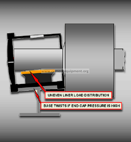
MISALIGNMENT OF BEARING RELATIVE TO ROLLER SHAFT. THE ROOT CAUSE IS HIGH END CAP PRESSURE CAUSED BY ROLLER AXIS MISALIGNMENT RELATIVE TO THE KILN AXIS.
COMMENT REGARDING THE ALIGNMENT OF TWO PIER KILNS
If we make the mistake of accepting that a kiln alignment is limited in scope to the alignment of the kiln axis, there is no compelling argument in favor of aligning two pier kilns. It is not possible, after all, to have two tire centers that are not on a straight line. If however, one accepts the premise of this paper that a comprehensive alignment has to address the alignment of all interacting moving components, the need for periodic alignment of two pier kilns is obvious. Thrust loads on support rollers will change over time, as will thrust roller pressures. End cap pressures and thrust collar pressures are subject to change and need to be measured and corrected periodically via bearing adjustments. Vertical shell deflection changes attributable to buildup will change the shell axis slopes at a tire – these changes will affect tire retainer pressures and may require bearing elevation adjustments. Roller bases may distort in response to high end cap pressures, so bearing housing slopes need to be compared to the roller slopes periodically. The prudent conclusions are that a) the alignment of two pier kilns needs to be checked annually and b) the scope of work must be far more comprehensive than is the case with most kiln alignments.
SUMMARY
To get the maximum return for an alignment investment, plants must demand a comprehensive alignment work scope as follows:
1. Locate the coordinates of the center of the shell on all piers. Laser based technology is preferred to assure maximum accuracy.
2. Determine the kiln axis misalignment by calculating the distance and angle between the shell center at each pier and the desired kiln axis. All calculations should be computer generated to minimize errors.
3. Measure the shell ovality on all piers.
4. Adjust all support rollers to straighten the kiln axis. The priority is to fine-tune pier load distribution in a manner that optimizes shell ovality (without exceeding limits on bearing pressures and hertz pressures).
5. Measure all roller shaft thrust collar pressures and bearing end cap pressures, depending on the bearing design. Adjust bearings as necessary to lower high thrust mechanism pressures. Properly done, these adjustments will assure that all support rollers are parallel to the kiln axis to within 0.008” per foot or less.
6. Measure the lateral tire movement on all piers to detect and quantify the effects of dogleg conditions that are of sufficient magnitude to jeopardize kiln stability.
7. Determine what support roller slope changes are necessary to align the plane of each tire perpendicular to the kiln axis. This procedure is necessary to eliminate high tire retainer pressures.
8. Assess the need to correct improper bearing liner load distributions by comparing bearing housing slopes to roller axis slopes.
9. Inspect all kiln components. Make prioritized written recommendations to improve kiln mechanical performance.
Unless the above procedures are specified in quotation requests and purchase orders, they will not be provided and kiln stability will be less than ideal. There are companies that are capable of providing a comprehensive alignment work scope; they should be given preference over companies whose alignment expertise is not sufficiently specialized.
If readers would like elaboration or justification for any of the above technical claims, they can contact the author at [email protected] Challenges to the above opinions are welcome.
Kindly add a seach option