Contents
Third Generation Clinker Cooler for Reduced Operating and Maintenance Cost
Attention!! to Download Most Important Books in Cement industry reviewed from more than two thousands people + Manuals and noted from big Cement Companies like F L S , Holcim Lafarge , Cemex , + Excel sheets for calculations process Click here Now
Abstract – The Company had a 45-year old, original, first generation reciprocating grate cooler that was due for total rebuild. The remainder of the kiln line had been updated over time which had resulted in increased throughput, but the cooler had never been updated. Through a strong partnership between the original equipment supplier (OEM), the corporate engineering team, and the plant personnel from project conception through project completion, the Company was able to implement the latest generation of clinker cooler technology. Operational performance has shown significant savings in fuel consumption and electrical energy consumption. Further, an increase in resulting product strength has allowed for a reduction in Blaine targets for finished cement, helping to position the Company to meet current and future market challenges and opportunities.
I. INTRODUCTION
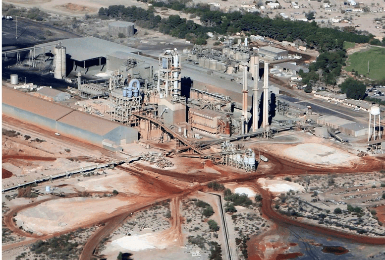
The preheater-type dry process kiln line #4 (Fig. l) was originally designed and supplied in l972 at a rated capacity of l,800 stph to supplement the 3 older vintage long dry kilns. The preheater line was subsequently upgraded over the next 30 years to include calciner firing, indirect coal firing to the main burner and tower, new tower vessels, a vertical roller mill for raw meal, and a new downcomer and kiln baghouse upgrade. This package brought the rated clinker production capacity to 3,200 stph. Throughout these 30 years of improvement, the clinker cooler was not upgraded.
Fig. l. The Company’s Cement Plant located in southern AZ, USA
The company worked with the original equipment manufacturer (OEM) to replace the original reciprocating grate cooler system with a modern reciprocating bar cooler system. The modifications included: replacing all cooler internals, modifying the clinker cooler casing, installing a new fixed inlet, replacing the hammer-type breaker with an electromechanical roll breaker, replacing all undergrate fans, and moving the coal mill hot gas takeoff from the tertiary air duct to the cooler vent duct.
Unlike previous system upgrades, the primary driver of the upgrade was not to increase hourly throughput, but to reduce downtime due to maintenance, reduce fuel and power consumption, and increase cement strength.
II. CLINKER COOLER SYSTEM MODIFICATIONS
A Clinker Cooler Internals
The core of the project was replacement of the existing reciprocating grate cooler with a reciprocating bar cooler (Fig. 2). The new reciprocating bar cooler features separation of the conveying and cooling systems. A stationary grate line seals the active area from the undergrate air chambers, eliminating fall through and fall through conveying systems. Air distribution plates are equipped with mechanical flow regulators. Transport utilizes 5 lines of movable bars with customizable stroke length, allowing optimization of transport efficiency and horizontal installation.
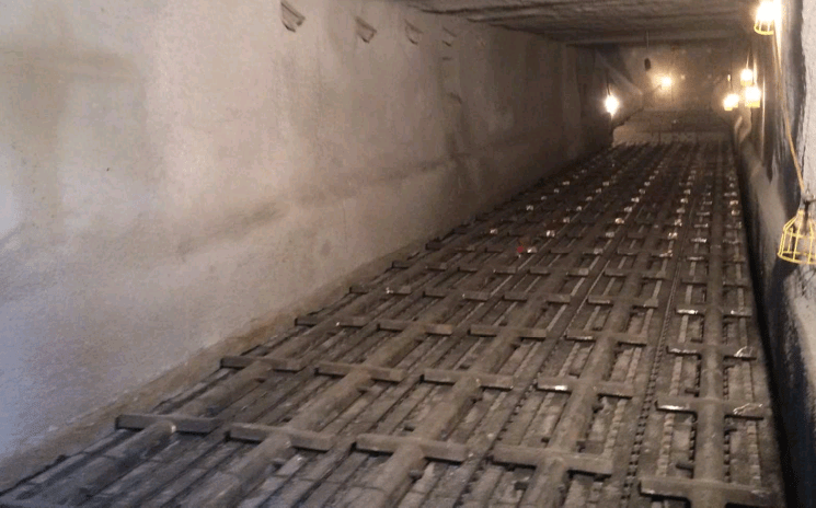
Fig. 2. View of Grateline of New Cooler
A fixed inlet section with controlled air blasters composed of 10 grates wide by 5 rows long of stepped stationary plates with mechanical flow regulators was installed at the inlet end of the cooler.
As stated by McKervey et al. [1]:
‘This design combines the advantages of a stationary inlet section – long service life and good cooling air distribution – with the advantages of pneumatic clinker conveying – good clinker distribution and elimination of snowmen.
The inlet incorporates controlled air blasting technology as shown in Fig. 3. Blast air is directed into the grate through the same openings that the cooling air moves through. Air blasting takes place on three levels of each grate. When the air blasters engage, air flow from the undergrate is blocked off and the air blast is prevented from going into the undergrate. These blasts reduce and/or eliminate snowmen formation. After the inlet compartment, the rest of the cooler is comprised of an 10 grate wide by 43 row horizontal (equivalent grate length) grate line constructed by a series of standard units that are 5 grates wide by 7 grates long. These units come fully assembled to ease installation.
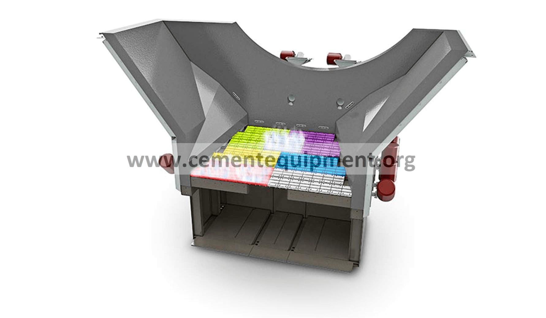
Fig. 3. Inlet provides cooling and blasting [I]
The grate line is composed of stainless steel fabricated air distribution plates with replaceable components. The grate line is completely stationary during operation, eliminating the need for spillage conveyors.
Each grate plate is equipped with a mechanical flow regulator (Fig. 4), which is a weighted automatic air damper system, which opens and closes to adjust the cooling air pressure as the clinker bed depth changes (Fig. 5). The drive plates penetrate the grate line but are sealed by the use of profile plates which provide a labyrinth type seal to minimize air leakage around the drive plates as well as material leakage to the undergrate compartments.
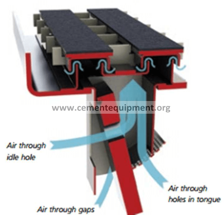
Fig. 4. Mechanical air flow regulator [I]
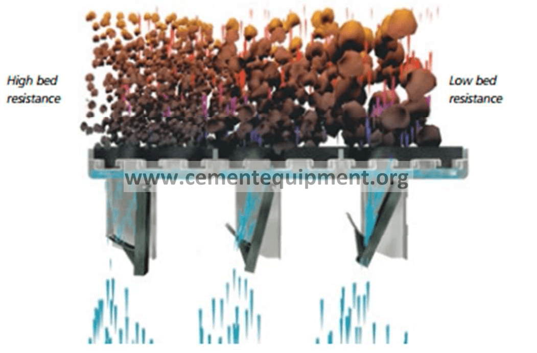
Fig. 5. Constant airflow irrespective of overgrate conditions [1]
Drive plates are driven by hydraulic cylinders mounted in the under grate chambers. The conveyance of clinker is controlled by the use of reciprocating bars which are mounted to the drive plates above the grate line. Reciprocating bars are mounted in place by a system of steel wedges held by pins, which will allow for easy replacement when items wear.
The hydraulic drives are a closed-loop hydraulic system. A cabinet mounted, programmable logic control system is provided with each drive system. The power unit is preassembled on a skid including: reservoir with level switches, temperature sensors, oil heaters and oil filtration and cooling system. Each drive has a pump system. A standby pump was provided to allow maintenance without shutting down any of the drives.”
The original grate cooler was of a stepped design; the first drive of the cooler was 8 grates wide, while the second and third drives were 10 grates wide. The new cooler was designed to fit within the footprint of the 10 grate wide section, necessitating the replacement of the casing in the first section. Figure 6 highlights the areas of the new cooler housing.
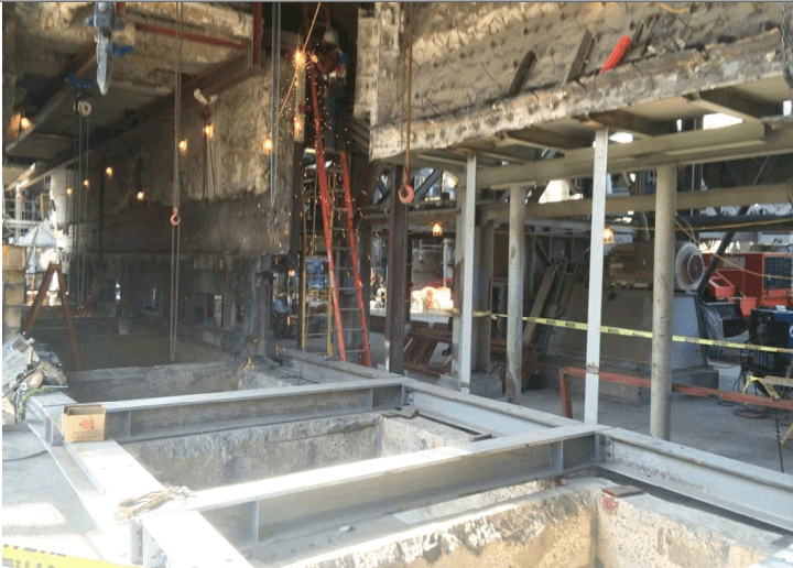
Fig. 6. Clinker Cooler Casing Drawing
- Heavy Duty Roller Breaker
The original hammer breaker was identified as a high intensity maintenance consumer. The breaker required complete overhaul every 4-5 months, costing 12-24 hours of downtime per overhaul.
The machine consists of a series of toothed rolls that transport, screen, and crush material (Fig. 7). Clinker drops onto the single transport roll that rotates in the direction of clinker flow. This roll serves to screen out smaller clinker particles that will pass through the gaps between transport roll and the first crushing roll. The larger particles are transported to the crushing rolls which rotate in opposite directions and break up the clinker into smaller and more uniform particles. The crushed clinker then drops from roller breaker into the discharge hopper and into the existing drag chain conveyor.
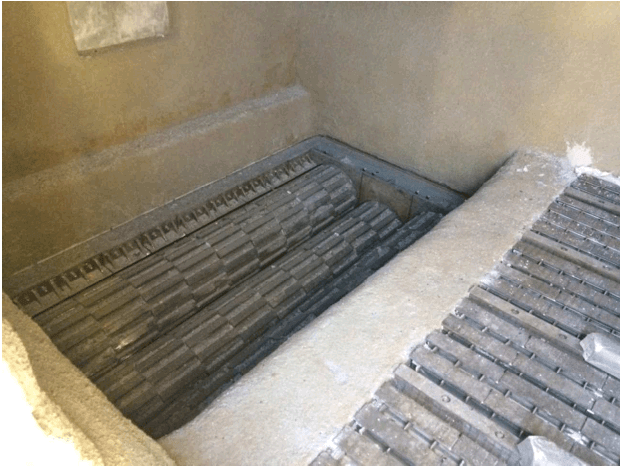
Fig. 7. View of New Heavy Duty Roller Breaker
- Clinker Transport
The Company and the OEM also analyzed the clinker transport system. The Plant utilized a common drag chain conveyor for transport of the crushed clinker and the clinker fall through from the reciprocating grate cooler. As the drag chain was in good condition and of sufficient capacity to support the new reciprocating bar cooler, the Company elected to retain this component. The drag chain was shortened; eliminating the section where the clinker fall-through was previously.
- Clinker Cooler Undergrate Fans
The clinker cooler undergrate fans were identified as a point of interest as well. All fans were at least 25 years old, with some over 40 years old. 4 of the existing fans were medium voltage, providing a challenge as the Company wanted to eliminate damper control and use Variable Frequency Drives to control fan performance. After analyzing the existing fans, 2 were identified as possibilities for re-use. However, the anticipated cost and time necessary to retrofit the fans far outweighed the cost to supply new fans. 7 new fans equipped with Variable Frequency Drives were installed, operating at 2.335 Nm3/kg.cl.
The cooler fan locations were also changed. The original design had all fans on the north side of the cooler (Fig. 8). To
reduce downtime during project execution and remove complexity from the shutdown work, the Company elected to locate four of the new fans on the south side of the cooler (Fig. 9).
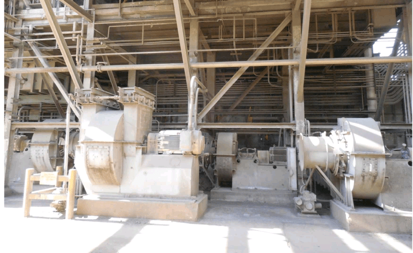
Fig. 8. View of Old Undergrate Fans
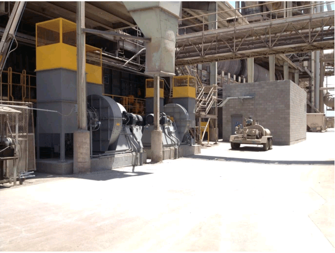
Fig. 9. View of New Undergrate Fans
- Coal Mill Takeoff
The coal mill takeoff was located in the tertiary air duct immediately after the tertiary air takeoff point (Fig. 10). The gas was then tempered via bleed air, routed through a cyclone, and tempered again via bleed air before entering the mill system. High coal mill temperature had led to 2 explosions within the coal mill system, making this a very high priority safety issue. Additionally, coal mill fan power was consumed by the pressure drop though the cyclone and high grade heat in the tertiary air was being wasted.
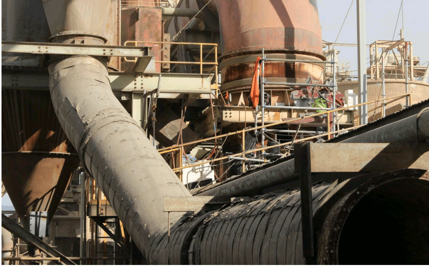
Fig. 10. View of Original Coal Mill Takeoff
The project team identified an opportunity to route gas directly from the cooler vent takeoff to the coal mill, with less bleed air necessary (Fig. 11). The team also determined that gas did not need to be dedusted in a cyclone, as mill and burner operation could be changed to accommodate a higher dust concentration.
The change in takeoff resulted in a marginal effective ash increase in the coal at the burner pipe, but saved on fan power for the coal mill and cooler baghouse fan.
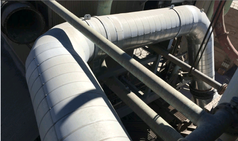
Fig. 11. View of Relocated Coal Mill Takeoff
Phase I: Erection and Commissioning Timeline
-
- Feb 8, 2016 – Site work begins on fan foundations and hydraulic room
- Feb 8, 2016 – Kiln shutdown for cooler work and planned maintenance (unexpected early shutdown)
- March 2016 – Cold commissioning and signal testing began.
- March 15, 2016 – Refractory work started in cooler and kiln hood
- April 9-11, 2016 – Cooler hydraulic system test run without load for 40 hrs.
- April 12, 2016 – Refractory dry-out
- April 12, 2016 – Kiln preheat began.
- April 14, 2016 – Cooler operation with load and stabilized at 80% production.
- June 27, 2016 – First performance guarantee test passed
| Project Results | |
| Clinker Temperature Reduction | 96 (F) |
| Fuel Consumption | -7.1 % |
| Electrical Power Consumption | -10% to -20% |
| Product Quality Improvement (Blaine Target Decrease) | 4% |
| Tertiary Air Temperature Increase | 259 (F) |
III. CONCLUSION
Building on a long, successful and healthy relationship with the original equipment supplier, the Company upgraded their clinker cooler system in Arizona. The total package of clinker cooler, new fixed inlet, new undergrate fans with VFDs, and relocated coal mill takeoff duct has reduced overall fuel consumption by 7.1% and electrical consumption by 10-20%, while allowing cement Blaine targets to be decreased 4%.
REFERENCES
[1] G. McKervey et al., “Pyro and Raw Mill Modifications to Achieve 2,200 STPD,” in 2014 IEEE-IAS/PCA Cement Industry Technical Conference, 2014 © IEEE. doi: 10.1109/CITCon.2014.6820118
Attention!! to Download Most Important Books in Cement industry reviewed from more than two thousands people + Manuals and noted from big Cement Companies like F L S , Holcim Lafarge , Cemex , + Excel sheets for calculations process Click here Now